1
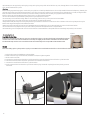
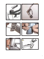
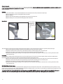
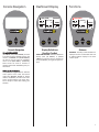
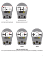
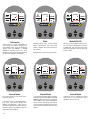
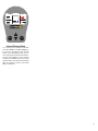
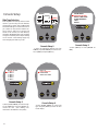
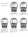
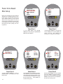
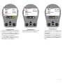
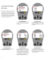
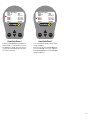
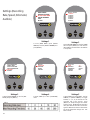
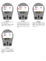
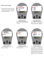
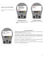
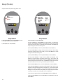
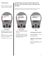
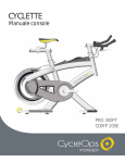
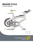
INDOOR CYCLE
Console Manual
PRO 300PT
COMP 200E
Table Of Contents
System Overview..................................................................................................................................................................................................p.2
Installation..............................................................................................................................................................................................................p.4
Zero Torque............................................................................................................................................................................................................p.6
Console Navigation.............................................................................................................................................................................................p.7
Dashboard Display..............................................................................................................................................................................................p.7
Functions................................................................................................................................................................................................................p.7
Console Set-Up.....................................................................................................................................................................................................p.12
Setting User Information...............................................................................................................................................................p.13
Ride Type Selection.........................................................................................................................................................................p.13
Power Zone Based Ride.................................................................................................................................................................p.14
Heart Zone Based Ride..................................................................................................................................................................p.16
Setting (Recording Rate, Speed, Odometer, Audible).........................................................................................................p.18
Setting (Averages)............................................................................................................................................................................p.20
Setting (Zeros)...................................................................................................................................................................................p.22
Setup (Time & Date)........................................................................................................................................................................p.23
Clear Memory.....................................................................................................................................................................................p.24
Setup Modes......................................................................................................................................................................................p.25
Test Information (Current Firmware Version, LCD, Backlight, Hub Heart Wheel, Torque, Data Ride and Data Test)........p.25
Note * Never disassemble the main unit, as it cannot be reassembled.
* Handle the main unit carefully and avoid subjecting it to any shocks.
* Do not use thinner or other solvents to clean parts such as the main unit and sensor, as they may dissolve the plastic console casings.
* To clean these parts wipe them with a cloth soaked in a weak mixture of neutral detergent and water. Avoid spraying the unit directly with solvent
mixture.
* The console is water resistant, not water proof. Avoid sustained water contact and do not deliberately place the unit in water.
* If you are not familiar with bike maintenance please contact a professional bicycle mechanic. The power measuring components of the Pro 300PT
PowerTap flywheel assembly is highly complex and should only be serviced by Saris Cycling Group.
*During the course of repair DO NOT remove the torque tube on the Pro 300PT model. There are no serviceable parts inside. Special tools are
required for reassembly and calibration. If problems are suspected contact Saris Cycling Group directly at 800-783-7257 (001 608 274 6550).
System Overview
Congratulations! You have just purchased the finest indoor training device available. This bike has many features that distinguish it from any other
indoor cycle on the market. The CycleOps Indoor Cycle mimics the custom fit and feel of your own bike out on the road, in an indoor setting. The
CycleOps Pro 300 PT uses the proven PowerTap technology to give you real-time feedback on your training intensity. The console and included software (Comp 200E and Pro 300PT only) allow you to download your rides to a PC and track your progress over time. If you have any issues, comments
or concerns, don't hesitate to give us a call at 800-783-7257 (001 608 274 6550), or visit us at www.cycleops.com.
Upgrades
The Sport 100 is upgradeable to Comp 200E capabilities via part #16811. There is no option to upgrade any bike to the Pro 300PT; it must be
purchased outright.
Console Features
Both the Comp 200E and Pro 300 PT Indoor Cycles are equipped with a handlebar mounted console unit. The console receives a wired signal from the
transmitter located on the rear left dropout. Speed and cadence on the Comp 200E, as well as watts and torque on the Pro 300PT, are interfaced from
the rear hub signal. In addition to these metrics, the console displays current heart rate via a non-coded telemetry signal (chest strap)
Package Contents
Part #
16062
13971
16104
15661
16198
16068
16798
2
Comp 200E and Pro 300 PT Only
Console
Chest Strap
USB Cable
Software CD
Thumbscrew Console Knobs
Cradle Bracket
Allen Lim Power CD
Qty
1
1
1
1
2
1
1
Technical Specs
Accuracy
Signal Transmission
Interval Data Storage
Interval Display
Operational Temperature
Battery Life (Hub)
Battery Life (Console)
Battery Type (Hub)
Battery Type (Console)
Freehub fixing bolt torque
+/-1.5% (Pro 300PT)
Digital RF
Unlimited
9 Intervals (internal recording)
0 to 40 degrees c or 32 to 104 f
1000 hours approx.
100 hours approx.
N-Type, 1.5 volt/ANSI 910/IEC LR1 (2 ea)
AAA type, 1.5 volt (3 ea)
400-450 inch-lbs.
Range of Measurement
Power
Torque
Speed
Distance
Trip Time
Cadence
Total energy
Odometer
Heart Rate
Maximum Rider Weight
0-1999 Watts
0-1999 inch-lbs.
2-59 mph (3-95 KPH)
0.00 to 9999.99 (Miles)
0.00.00-999.99 Minutes
40-140 RPM (Revolutions per Minute)
0-99999 Kilojoules
0-99999 Miles or Kilometers
0-255 BPM (Beats per Minute)
300 lbs.
Warranty
The CycleOps Indoor Cycles are designed specifically for the home use and as such carry the following warranty:
All Saris Cycling Group Indoor Cycle products are warranted to the retail purchaser to be free from defects in materials and workmanship. Warranty coverage valid to the original purchaser only and proof of purchase will be required.
Residential Environment:
Frame: Lifetime
Parts: 3 years
Labor: 1 year
Electronics: 1 year
This warranty excludes wear items that need to be replaced due to normal wear and tear.
This warranty does not cover:
1. Any component on original equipment that carries a separate consumer warranty of the parts supplier.
2. Normal wear and tear.
3. Any damage, failure or loss caused by accident, misuse, neglect, abuse, improper assembly, improper maintenance, or failure to follow
instructions or warnings in Owner's Manual.
4. Use of products in a manner or environment for which they were not designed.
FCC Statement of Compliance:
Statement of Compliance for FCC and Industry Canada:
Saris Cycling Group, Inc.
Model #: PowerTap SL 2.4
IC: 6459A-SL2P401
FCC ID: T8P-SL2P401
"This device complies with Industry Canada and Part 15 of the FCC Rules. Operation is subject to the following two conditions: (1) This device may not cause harmful interference, and (2) this device must accept any interference received, including interference that may cause undesired operation."
The term "IC:" before the radio certification number only signifies that Industry Canada technical specifications were met.
Changes or modifications to this device not expressly approved by the party responsible for compliance with FCC regulations (the manufacturer) could void the user's
authority to operate the equipment.
This equipment has been tested and found to comply with the limits for a Class B digital device, pursuant to part 15 of the FCC Rules. These limits are designed to provide
reasonable protection against harmful interference in a normal installation. This equipment generates, uses and can radiate radio frequency energy and, if not installed and
used in accordance with the instructions, may cause harmful interference to radio communications. However, there is no guarantee that interference will not occur in a particular installation
Limitations:
The foregoing warranties are in lieu of and exclude all other warranties not expressly set forth herein, whether express or implied by operation of law or
otherwise, including, but not limited to, warranties of merchantability or fitness for a particular purpose. Saris Cycling Group shall in no event be liable for
incidental or consequential losses, damages or expenses in connection with its exercise products. Saris Cycling Group's liability hereunder is expressly limited to the replacement of goods not complying with this warranty or, at Saris Cycling Group election, to the repayment of an amount of the purchase
price of the exercise product in question. Some states do not permit the exclusion or limitation of implied warranties or incidental or consequential damages, so the preceding limitations and exclusions may not apply to you.
Procedures: Warranty service will be performed by Saris Cycling Group or an authorized Saris Cycling Group Dealer. The original purchaser must provide
proof of purchase. Service calls and/or transportation to and from the Authorized Saris Cycling Group Dealer are the responsibility of the purchaser. 1.
Saris Cycling Group will have the option to repair or replace any product(s) which require warranty service.
2. Saris Cycling Group will replace any equipment frame that is structurally defective with a new frame or replace the unit with a unit of equal value. Saris
Cycling Group is not responsible for labor charges in replacing defective frames.
3. In the event a product cannot be repaired, Saris Cycling Group will apply a limited credit reimbursement toward another Indoor Cycle product of equal
or greater value.
4. Saris Cycling Group is not responsible for dealer labor charges for component changeovers completed after labor-related warranty period(s) stated
herein.
5. If you elect to repair an exercise product or part yourself, using the services of someone other than an Authorized Saris Cycling Group Dealer, or use a
replacement part not supplied by Saris Cycling Group, Saris Cycling Group shall not be liable for any cost, damage, failure or loss caused by the use of
such unauthorized service or parts.
5. If you elect to repair an exercise product or part yourself, using the services of someone other than an Authorized Saris Cycling Group Dealer, or use a 3
replacement part not supplied by Saris Cycling Group, Saris Cycling Group shall not be liable for any cost, damage, failure or loss caused by the use of
such unauthorized service or parts.
Cautions
Before starting any exercise program, consult with your physician or health professional. He or she can help establish the exercise frequency, intensity (target heart rate, power zone) and time appropriate for your particular age and condition. If you have any pain or tightness in your chest, an irregular heartbeat, shortness of breath, feel faint or have any discomfort while you exercise, STOP! Consult your physician before continuing.
Failure to follow any of these safeguards may result in injury or serious health problems.
*Do not remove feet from pedals while CycleOps Indoor Cycle flywheel is in motion.
*Do not attempt to ride the bike at high RPM's or in a standing position until you have practiced at lower RPM's.
*Do not place fingers or any other objects into moving parts of the exercise equipment.
*Keep children and pets away from the CycleOps Indoor Cycle while the machine is in use. Do not allow children to ride on the CycleOps Indoor Cycle.
Pedal travel ranges are designed and intended for adults.
*Never turn pedal crank arms by hand. To avoid entanglement and possible injury, do not expose hands or arms to the drive mechanism.
*Do not dismount the CycleOps Indoor Cycle until both the pedals and the flywheel are at a complete STOP.
*After exercising, turn the adjustment control knob clockwise to increase tension so the pedals will not rotate freely and possibly hurt someone.
Figure 1
Installation
Heart Rate Monitor Strap
Position the heart rate monitor strap on your torso as pictured in figure 1. The strap should rest just beneath the pectoral
muscles of the chest. Make sure the electrodes on the strap are slightly moist where it contacts the skin for best results.
The heart rate strap must be worn to enable the heart rate functionality of the Comp 200E and Pro 300PT models.
Bracket
When first setting up the CycleOps Indoor Cycle you must attach the console bracket to the bike. To do this follow the instructions below:
A. Place bracket onto the handlebars as shown below.
B. Insert screws through console bracket, handlebar bracket, and tighten together.
C. Slide console onto base.
D. Connect the console wire to the Indoor Cycle frame wire by removing the twist tie on the indoor cycle frame wire.
E. Discard the twist tie, attach the plastic grommet to the console wire as shown.
F. Connect the console wire to the indoor cycle frame wire.
G. Push connected wire into the Indoor Cycle frame until the plug is inserted completly; then insert plastic grommet
into frame.
A
4
B
C
D
E
F
G
H
5
Console to bracket
To connect the console to the bracket, slide the console down onto the bracket. Be sure to slide the console completely down onto the bracket to ensure
a solid connection between the console and the bracket. Make sure the contact points between the console and bracket remain clean and free from
moisture or debris.
Batteries
The console ships with batteries. In the event the batteries need to be replaced over time, follow these simple steps:
1. Remove the back cover with a small philips head screwdriver
2. Remove batteries
3. Replace with fresh AAA batteries, paying attention to properly line up the poles
4. Replace battery door and secure with small philips head screwdriver
Reed Switch
The Comp 200E is
equipped with a
reed switch located on the left rear
dropout.
This switch picks up the speed and cadence readings from the flywheel. In the event the switch needs to be replaced, follow these steps:
1. Remove the existing reed switch from the frame by peeling it from the inside of the dropout.
2. Detach the switch from the frame wire by depressing the pinch lock and sliding the two connecters apart.
3. Attach the new switch on the inside of the rear, left dropout with the included double stick tape.
4. Slide the connecters together, making sure to align the pinch lock with the locking tooth on the frame wire. Tuck any slack in the cable
back inside the stay.
PT Receiver
The Pro 300PT is equipped with a PowerTap receiver on the rear left dropout. This receiver receives the speed, cadence and power data from the
PowerTap flywheel. In the event you need to replace the PowerTap receiver, follow these steps:
1. Remove the existing receiver by loosening the plastic screws, paying attention to loosen the square nuts on the inside of the dropout.
2. Detach the receiver from the frame wire by depressing the pinch lock and sliding the two connecters apart.
3. Attach the new receiver to the dropout with the plastic screws and square nuts (PIC).
4. Slide the connecters together, making sure to align the pinch lock with the locking tooth on the frame wire. Tuck any slack in the cable
back inside the stay.
IMPORTANT! How To Zero Torque
The torque must be zeroed to ensure that the PowerTap displays the most accurate power information. If the instantaneous power is positive, or negative, the torque needs to be zeroed. These operations must be done with NO tension on the chain or while stationary with NO force being placed on the
pedals. Also, the transmission icon must be illuminated.
To zero torque first ensure the transmission icon is showing then press [DOWN ARROW] to move the cursor to [WATTS]. Press [SELECT] to change to
[INCH-LBS]. Then hold down [SELCT] again until "0" is shown. Press [SELECT] to return to [WATTS]. The torque value will now read zero.
6
Console Navigation
Dashboard Display
RIDE TIME
MODE
SELECT
Console Navigation
UP and DOWN ARROWS
[UP ARROW] and [DOWN ARROW] are used
to scroll through the different fields on the
console. [UP ARROW] and [DOWN ARROW]
can also be used to move the navigation
cursor on the [MAIN MENU]. Additionally,
these arrows are used to increase or
decrease values when establishing user profile features.
00:00:00
MPH
H
CAD
WATTS
MODE
Functions
DISTANCE
0.00
MENU
MPH
H
HR
CAD
WATTS
SELECT
Display Definitions
(Scrolling Top Bar)
SCROLLING TOP BAR - From the dashboard
display press [UP ARROW] or [DOWN
ARROW] to move the cursor to the top bar
and press [SELECT] to toggle through functions.
MODE
MENU
HR
SELECT
Distance
DISTANCE - Total trip or interval distance is
displayed in miles or kilometers from 0.00
to 999.99. Distance displays in the same
units as speed.
MODE and SELECT Buttons
Use [MODE] to toggle between different
menu options and to enter the interval
mode (See [INTERVAL MODE] for further
details). Use [SELECT] to enter a new menu
screen. It also functions as an "enter" function to escape a screen after making your
selection.
7
RIDE TIME
ENERGY IN KJ
00:00:00
MPH
H
CAD
WATTS
MODE
MENU
MPH
H
HR
CAD
WATTS
MODE
SELECT
0
ODOMETER
255
MENU
MPH
H
HR
CAD
WATTS
SELECT
MODE
MENU
HR
SELECT
Ride Time
Total time that the user has ridden the
bike. Time is displayed in (hours : minutes :
seconds).
Energy in KJ
Odometer
This value is a measure of the total work
done over the course of your ride. Power is
displayed in watts and is a measure of the
intensity of work. Energy is calculated using
the following equation. See Table 1 for an
accurate estimate of Kjoules to Kcal conversion.
This is a rolling tally of the distance that you
have ridden the CycleOps Indoor Cycle.
This can be displayed in Miles or Kilometers
(see "Settings (Recording Rate, Speed,
Odometer, Audible)" for details).
Work or Energy (Joules) = Watts (Power) x
Time (Seconds)
Table 1
Estimated Caloric Correlation Factor- For an
accurate estimate of Kcals, multiply the
[ENERGY IN KJ] by the correlation factor best
describing your riding experience.
8
CLOCK
02:05:28P
MPH
H
CAD
WATTS
MODE
CLOCK
02:05:28P
MENU
MPH
H
HR
CAD
WATTS
MENU
HR
MODE
SELECT
SELECT
Clock
TRANSMISSION ICON
A real-time display of the current time of the
day (see "Setup (Time and Date)" for details)
When this icon is showing, there is a signal
transmitting from the hub to the receiver.
CLOCK
0
02:06:07P
MAX
0
MPH
0
CAD
H
0
WATTS
MODE
0
MPH
HR
CAD
0
02:06:07P
0
CLOCK
02:05:28P
AVG
0
MENU
SELECT
Maximum
CLOCK
H
0
WATTS
MODE
MENU
MPH
H
HR
CAD
WATTS
0
SELECT
Average
MODE
MENU
HR
SELECT
Current
MAX, AVG, and CURRENT Field
This line displays the current, maximum or average values for the ride or interval. From the dashboard display, press [UP ARROW] or [DOWN ARROW] to
move two spaces above [MENU]. Press [SELECT] to toggle between [MAX], [AVG], and current readings. Current readings are displayed when field is blank.
9
CLOCK
02:06:07P
MPH
H
CAD
WATTS
MODE
CLOCK
0
MENU
MPH
HR
CAD
SELECT
02:06:07P
CLOCK
02:06:07P
0
H
0
0
WATTS
MODE
MENU
MPH
HR
CAD
0
SELECT
H
MENU
INCH-LBS
MODE
HR
SELECT
Tachometer
Watts
Watts INCH-LBS
This functions as a visual interpretation of
how hard you are working compared to a
fixed wattage value. From the dashboard
display press [UP ARROW] or [DOWN
ARROW] to move the cursor to [H]. Press
[SELECT] to change the maximum tachometer value (400, 600, 800 or 1000 watts).
Real-time display of the current wattage
placed on the flywheel. This is your power
reading. Watts is derived from the following equation:
NOTE: If you press [SELECT] while the cursor is pointing to [WATTS] the line changes
to [INCH-LBS]. This is the raw torque value
that is being applied to the hub, NOT your
power in watts.
CLOCK
02:06:07P
Watts (Power) = Torque x Angular Velocity
CLOCK
02:06:07P
CLOCK
02:06:07P
INT: 1
MPH
H
CAD
WATTS
MODE
MENU
MPH
H
HR
CAD
WATTS
SELECT
MODE
INT: 1
MENU
MPH
H
HR
CAD
WATTS
SELECT
MODE
MENU
HR
SELECT
Interval Mode
Interval Mode
Interval Mode
The console works as a lap marker, and is
essentially always on.
2) To view interval specific data in the dashboard display press [UP ARROW] or [DOWN
ARROW] until the cursor icon is in the space
above [MENU]. Press and hold [MODE] for
two (2) seconds. This brings interval mode
to the foreground and [INT] and the interval number will constitute a third line in the
display.
3) When you wish to relegate the interval
information to the background press
[MODE] for two (2) seconds
1) From any location on the dashboard display press and release [MODE] and
[SELECT] simultaneously. [INT] and the
new interval # will briefly appear before disappearing again to the background in the
field located above [MENU].
10
CLOCK
02:06:07P
INT: 2
MPH
H
CAD
WATTS
MODE
MENU
HR
SELECT
Interval Memory Mode
1) To access stored interval information
press [UP ARROW] or [DOWN ARROW] to
scroll to the interval line (See Interval
Mode) and hold [MODE] for two (2) seconds. This brings interval mode to the foreground. Press [MODE] to move interval
numbers up, and [SELECT] to move interval
numbers down. Current intervals read black
[INT] and memory intervals read white
[INT] in a black box.
11
Console Setup
Ride Type Selection
Press any button to wake up and turn on the
console. If you are using it for the first time,
all data will be stored under [USER A] with
the default settings for a 150 lb male born on
Jan 1, 2004. You may need to reset the console if there is data from a previous ride
stored on the console (see "Clear Memory"
for details). NOTE: Parameters such as weight
and age do not affect power output readings
on the console. These settings apply only
when analyzing the data on your PC.
CLOCK
02:06:07P
MPH
H
CAD
WATTS
MODE
MODE
SELECT
Console Setup 3
Console Setup 4
3) Press [DOWN ARROW] to scroll through
six (6) [USER] files and press [SELECT] to
choose the user. (See "Setting User
Information" to establish a user profile).
4) Press [DOWN ARROW] to choose ride
type and press [SELECT] to return to dashboard display.
12
SELECT
2) Press [SELECT] to enter [RETURN TO
RIDE].
CYCLE COMPUTER
POWER ZONE
HEART RATE ZONE
SELECT
MODE
1) From the dashboard display press [UP
ARROW] or [DOWN ARROW] to move the cursor to [MENU] and press [SELECT].
RIDE TYPE
MODE
SELECT
Console Setup 2
1
2
3
4
5
6
A
B
C
D
E
F
HR
Console Setup 1
RETURN TO RIDE
USER
USER
USER
USER
USER
USER
MENU
MAIN MENU
RETURN TO RIDE
SETUP USER RIDE
CLEAR MEMORY
TEST
SETUP
Setting User Information
This option allows you to set the personal profile
of up to six different individuals.
MAIN MENU
RETURN TO RIDE
SETUP USER RIDE
CLEAR MEMORY
TEST
SETUP
MODE
SELECT
CYCLE COMPUTER
POWER ZONE
HEART RATE ZONE
USER INFORMATION
SETTINGS
RETURN
MODE
Setup User Information 1
Setup User Information 2
1) From [MAIN MENU] press [DOWN
ARROW] to scroll to [SETUP USER RIDE] and
press [SELECT].
2) Press [DOWN ARROW] to scroll to [USER]
files and press [SELECT] to chose a user.
(See "Setting User Information" to establish
a user profile).
USER INFORMATION
USER INFORMATION
USER INFORMATION
NAME
USER A
BIRTH DATE
WEIGHT
GENDER
RESET
RETURN
NAME
USER A
BIRTH DATE
WEIGHT
GENDER
RESET
RETURN
NAME
USER A
BIRTH DATE
WEIGHT
GENDER
RESET
RETURN
MODE
05-01-43
199
MALE
SELECT
SELECT
MODE
05-01-43
199
MALE
SELECT
MODE
05-01-43
199
MALE
SELECT
Setup User Information 3
Setup User Information 4
Setup User Information 5
3) Press [DOWN ARROW] to scroll to [USER
INFORMATION] and press [SELECT].
4) Press [SELECT] and [UP ARROW] or
[DOWN ARROW] to enter letters. Press
[SELECT] to toggle through letters. Press
[SELECT] to accept changes and reenter
scrolling menu.
5) Repeat step 3 to set [BRITH DATE],
[WEIGHT], and [GENDER] information.
NOTE: This data does not affect console
power data.
6) To reset user settings, press [DOWN
ARROW] to scroll to [RESET] and press
[SELECT].
7) To begin a ride, press [DOWN ARROW] to
scroll to [RETURN] and press [SELECT].
Press [DOWN ARROW] to scroll to [RETURN]
and press [SELECT].
13
Power Zone Based
Ride Setup
Power zones separate your power data into
discrete bins, or intervals, specific to a particular energy or physiological system. From
short maximal efforts to long maximal
efforts these energy systems run along a
continuum from anaerobic to aerobic metabolic pathways. These bins help to separate
these efforts to better quantify your training stimulus.
MODE
SELECT
SELECT
1
2
3
4
5
6
USER
USER
USER
USER
USER
USER
A
B
C
D
E
F
MODE
SELECT
Power Zone 2
1) From [MAIN MENU] press [DOWN
ARROW] to scroll through to [SETUP USER
RIDE] and press [SELECT].
2) Press [DOWN ARROW] to scroll through
six (6) [USER] files and press [SELECT] to
select a user file. (See "Setting User
Information" to establish a user profile).
ANAR TH
ZONE 1
ZONE 2
ZONE 3
ZONE 4
NEXT ZONE
RETURN
CYCLE COMPUTER
POWER ZONE
HEART RATE ZONE
RETURN TO RIDE
Power Zone 1
POWER ZONE 1
RIDE TYPE
MODE
MAIN MENU
RETURN TO RIDE
SETUP USER RIDE
CLEAR MEMORY
TEST
SETUP
MODE
POWER ZONE 1
450
0%-55%
55%-75%
75%-90%
90%-105%
SELECT
ANAR TH
ZONE 1
ZONE 2
ZONE 3
ZONE 4
NEXT ZONE
RETURN
MODE
450
0%-55%
55%-75%
75%-90%
90%-105%
SELECT
Power Zone 3
Power Zone 4
Power Zone 5
3) Press [DOWN ARROW] to scroll to
[POWER ZONE]. Press [SELECT] to enter
Power Zone 1.
4) Press [SELECT] to manually input a previously determined anaerobic threshold (AT)
value (displayed in watts) for which % values will be based. Press [SELECT] to toggle
through digit values.
Press [SELECT] to
reenter scrolling menu.
5) Press [DOWN ARROW] to scroll to [ZONE
1] and press [SELECT] to enter the upper %
training zone. Press [UP ARROW] or [DOWN
ARROW] to adjust value and press [SELECT]
to reenter the scrolling menu.
14
POWER ZONE 1
ANAR TH
ZONE 1
ZONE 2
ZONE 3
ZONE 4
NEXT ZONE
RETURN
MODE
POWER ZONE 2
POWER ZONE 2
450
0%-55%
55%-75%
75%-90%
90%-105%
SELECT
ZONE 5
ZONE 5
ZONE 5
PREVIOUS ZONE
RESET
RETURN
MODE
105%-120%
120%-133%
133%-165%
SELECT
ZONE 5
ZONE 5
ZONE 5
PREVIOUS ZONE
RESET
RETURN
MODE
105%-120%
120%-133%
133%-165%
SELECT
Power Zone 6
Power Zone 7
Power Zone 8
6) Press [DOWN ARROW] and then press
[SELECT] to adjust [ZONE 2]. Repeat steps
3, 4, and 5 to set [ZONES 2-4]. NOTE: The
lower % training zone will automatically set
to the previous zone's upper limit.
7) Once [ZONE 1-4] information has been
set, press [DOWN ARROW] to scroll to
[NEXT ZONE] and press [SELECT].
8) In Power Zone 2 screen repeat steps 3, 4,
and 5 to set information for [ZONE 5-6].
9) To reset default zone settings, press
[DOWN ARROW] to scroll to [RESET] and
press [SELECT].
10) To begin a power zone based ride, press
[DOWN ARROW] to scroll to [RETURN] and
press [SELECT]. Press [DOWN ARROW] to
scroll to [RETURN] and press [SELECT] once
again.
15
Heart Rate Zone Based
Ride Setup
Heart rate zones separate your heart rate data
into discrete bins, or intervals, specific to a particular energy or physiological system. From
short maximal efforts to long maximal efforts
these energy systems run along a continuum
from anaerobic to aerobic metabolic pathways.
These bins help to separate these efforts to better quantify your training stimulus.
MODE
SELECT
1
2
3
4
5
6
USER
USER
USER
USER
USER
USER
A
B
C
D
E
F
MODE
SELECT
Heart Rate Zone 1
Heart Rate Zone 2
2) Press [DOWN ARROW] to scroll to [USER]
files and press [SELECT] to chose a user.
(See "Setting User Information" to establish
a user profile).
TYPE
ANAR TH
ZONE 1
ZONE 2
ZONE 3
ZONE 4
RESET
SELECT
RETURN TO RIDE
1) From [MAIN MENU] press [DOWN
ARROW] to scroll to [SETUP USER RIDE] and
press [SELECT].
HEART RATE ZONE
HEART RATE ZONE
CYCLE COMPUTER
POWER ZONE
HEART RATE ZONE
USER INFORMATION
SETTINGS
RETURN
MODE
MAIN MENU
RETURN TO RIDE
SETUP USER RIDE
CLEAR MEMORY
TEST
SETUP
MODE
MAX
162
50%-83%
83%-91%
91%-93%
93%-160%
RETURN
SELECT
TYPE
ANAR TH
ZONE 1
ZONE 2
ZONE 3
ZONE 4
RESET
MODE
MAX
162
50%-83%
83%-91%
91%-93%
93%-160%
RETURN
SELECT
Heart Rate Zone 3
Heart Rate Zone 4
Heart Rate Zone 5
3) Press [DOWN ARROW] to scroll to [HEART
RATE ZONE] and press [SELECT].
4) Press [SELECT] and press [DOWN
ARROW] to toggle between [AT] or [MAX]
settings. Press [SELECT] to reenter scrolling
menu. NOTE: [AT] sets % heart rate values
to be based off a previously determined AT
test, and [MAX] sets % heart rate values to
be based off either a predicted or previously determined MAX heart rate value.
5) Select [ANAR TH] to set the heart rate
value for which % values will be based.
Press [SELECT] to toggle through digit values. Press [SELECT] to accept changes and
reenter scrolling menu.
16
HEART RATE ZONE
TYPE
ANAR TH
ZONE 1
ZONE 2
ZONE 3
ZONE 4
RESET
MODE
HEART RATE ZONE
MAX
162
50%-83%
83%-91%
91%-93%
93%-160%
RETURN
SELECT
TYPE
ANAR TH
ZONE 1
ZONE 2
ZONE 3
ZONE 4
RESET
MODE
MAX
162
50%-83%
83%-91%
91%-93%
93%-160%
RETURN
SELECT
Heart Rate Zone 6
Heart Rate Zone 7
6) Press [DOWN ARROW] and [SELECT] to
adjust [ZONE 2]. Continue this process to
set [ZONES 1-4]. NOTE: The lower % training zone will automatically set to the previous zone's upper limit.
7) To reset default [ZONE] settings select
and press [RESET].
8) To begin a ride, press [DOWN ARROW] to
scroll to [RETURN] and press [SELECT].
Press [DOWN ARROW] to scroll to [RETURN]
and press [SELECT].
17
Settings (Recording
Rate, Speed, Odometer,
Audible)
MAIN MENU
RETURN TO RIDE
SETUP USER RIDE
CLEAR MEMORY
TEST
SETUP
MODE
CYCLE COMPUTER
POWER ZONE
HEART RATE ZONE
USER INFORMATION
SETTINGS
RETURN
MODE
SELECT
SELECT
RETURN TO RIDE
1
2
3
4
5
6
USER
USER
USER
USER
USER
USER
A
B
C
D
E
F
MODE
SELECT
Settings 1
Settings 2
1) From [MAIN MENU] press [DOWN
ARROW] to scroll to [SETUP USER RIDE] and
press [SELECT].
2) Press [DOWN ARROW] to scroll to [USER]
files and press [SELECT] to enter the file.
(See "Setting User Information" to establish
a user profile).
SETTINGS
COMPUTER
COMPUTER
AVERAGE
ZEROS
RETURN
RATE
MPH-KPH
ODOMETER
AUDIBLE
RETURN
MODE
SELECT
10
MPH
00255
OFF
MODE
SELECT
Settings 3
Settings 4
Settings 5
3) Press [DOWN ARROW] to scroll to [SETTINGS] and press [SELECT].
4) Press [SELECT] to enter [COMPUTER]
mode.
5) Press [SELECT] to enter [RATE]. Use [UP
ARROW] or [DOWN ARROW] to toggle
between 1, 2, 5, 10, 30 seconds for the
recording rate of the console. Press
[SELECT] to accept changes and reenter
scrolling menu. NOTE: Different recording
rates yield different amounts of total storage time. Refer to the chart on left to select
the most appropriate storage rate. See
Table 2 at left.
Table 2
18
COMPUTER
RATE
MPH-KPH
ODOMETER
AUDIBLE
RETURN
COMPUTER
10
MPH
00255
OFF
MODE
SELECT
RATE
MPH-KPH
ODOMETER
AUDIBLE
RETURN
MODE
COMPUTER
10
MPH
00255
OFF
SELECT
RATE
MPH-KPH
ODOMETER
AUDIBLE
RETURN
10
MPH
00255
OFF
MODE
SELECT
Settings 6
Settings 7
Settings 8
6) Press [DOWN ARROW] to scroll to [MPHKPH] and press [SELECT].
7) Press [DOWN ARROW] to toggle
between [MPH] and [KPH] and press
[SELECT] to reenter scrolling menu.
8) Press [DOWN ARROW] and scroll to
[ODOMETER] and press [SELECT]. Use [UP
ARROW] or [DOWN ARROW] to manually
enter the starting odometer reading. Press
[SELECT] to toggle through digit values.
Press [SELECT] to reenter the scrolling
menu.
9) Press [DOWN ARROW] and scroll to
[AUDIBLE] and press [SELECT]. Use [UP
ARROW] or [DOWN ARROW] to toggle
between [ON] and [OFF] and press
[SELECT] to accept changes and reenter
scrolling menu.
COMPUTER
RATE
MPH-KPH
ODOMETER
AUDIBLE
RETURN
10
MPH
00255
OFF
MODE
SELECT
Settings 9
10) To begin a ride, press [DOWN
ARROW] to scroll to [RETURN] and
press [SELECT]. Press [DOWN ARROW]
to scroll to [RETURN] and press
[SELECT].
19
Settings (Averages)
These settings allow for better pacing during
Time Trial efforts by allowing for a slower update
of the display. Changing these settings applies
only the display console and does not affect the
recording rate for download
MAIN MENU
RETURN TO RIDE
SETUP USER RIDE
CLEAR MEMORY
TEST
SETUP
MODE
CYCLE COMPUTER
POWER ZONE
HEART RATE ZONE
USER INFORMATION
SETTINGS
RETURN
MODE
SELECT
SELECT
RETURN TO RIDE
1
2
3
4
5
6
USER
USER
USER
USER
USER
USER
A
B
C
D
E
F
MODE
SELECT
Setting (Averages) 1
Setting (Averages) 2
1) From [MAIN MENU] press [DOWN
ARROW] to scroll to [SETUP USER RIDE] and
press [SELECT].
2) Press [DOWN ARROW] to scroll through
six (6) [USER] files and press [SELECT] to
select a user file. (See "Setting User
Information" to establish a user profile).
SETTINGS
AVERAGE
COMPUTER
AVERAGE
ZEROS
RETURN
WATTS AVG
SPEED AVG
CADENCE AVG
HEART AVG
TORQUE AVG
RESET
RETURN
MODE
SELECT
MODE
2
3
5
REGULAR
1
SELECT
Setting (Averages) 3
Setting (Averages) 4
Setting (Averages) 5
3) Press [DOWN ARROW] to scroll to [SETTINGS] and press [SELECT].
4) Press [DOWN ARROW] to scroll to [AVERAGE] and press [SELECT].
5) Press [SELECT] to enter [WATTS AVG].
Press [UP ARROW] or [DOWN ARROW] to
determine the number of previous data
points used (1, 2, 3, 5, 10, 30) to determine
the average metric display on the console.
This function applies only to console data
averages and does not apply to downloaded information. Press [SELECT] to
accept changes and reenter the scrolling
menu.
20
AVERAGE
WATTS AVG
SPEED AVG
CADENCE AVG
HEART AVG
TORQUE AVG
RESET
RETURN
MODE
2
3
5
REGULAR
1
SELECT
Setting (Averages) 6
6) Repeat steps 3, 4, and 5 for [SPEED AVG]
and [CADENCE AVG]. Press [SELECT] to
accept changes and reenter scrolling
menu.
7) Press [DOWN ARROW] to scroll to [HEART
AVG] and press [SELECT].
8) Press [UP ARROW] or [DOWN ARROW] to
toggle between [FAST], [SLOW], and [REGULAR] averaging. Press [SELECT] to accept
changes and reenter scrolling menu.
Selecting a slower rate of display it allows
for better pacing during a time trial effort
by allowing for a slower update of the display.
9) Press [SELECT] to enter [TORQUE AVG].
Press [UP ARROW] or [DOWN ARROW] to
determine the number of previous data
points used (1, 2, 3, 5, 10, 30) to determine
the average. Press [SELECT] to accept
changes and reenter the scrolling menu.
Selecting a higher number of previous data
points used allows for better pacing during
a time trial effort by allowing for a slower
update of the display.
10) To reset user settings press [DOWN
ARROW] to scroll to [RESET] and press
[SELECT].
11) To begin a ride, press [DOWN ARROW]
to scroll to [RETURN] and press [SELECT].
Press [DOWN ARROW] to scroll to [RETURN]
and press [SELECT].
21
Settings (Zeros)
These settings determine if zero readings will be
included in average readings. For example,
when coasting zero powering readings are
recorded. This setting determines if these zero
coasting readings are included in the average
console display.
MAIN MENU
RETURN TO RIDE
SETUP USER RIDE
CLEAR MEMORY
TEST
SETUP
MODE
SELECT
Settings (Zeros)
1) From [MAIN MENU] press [DOWN ARROW]
to scroll to [SETUP USER RIDE] and press
[SELECT].
CYCLE COMPUTER
POWER ZONE
HEART RATE ZONE
USER INFORMATION
SETTINGS
RETURN
MODE
SELECT
Settings (Zeros)
3) Press [DOWN ARROW] to scroll to [SETTINGS] and press [SELECT].
1
2
3
4
5
6
USER
USER
USER
USER
USER
USER
A
B
C
D
E
F
MODE
SELECT
Settings (Zeros)
2) Press [DOWN ARROW] to scroll to through
six (6) [USER] files and press [SELECT] to
select a user file. (See "Setting User
Information" to establish a user profile).
SETTINGS
SETTINGS
WATTS AVG ZEROS YES
SPEED AVG ZEROS YES
CAD AVG ZEROS
YES
RESET
RETURN
WATTS AVG ZEROS YES
SPEED AVG ZEROS YES
CAD AVG ZEROS
YES
RESET
RETURN
MODE
SELECT
MODE
SELECT
Settings (Zeros)
Settings (Zeros)
4) Press [DOWN ARROW] to scroll to [ZEROS] and
press [SELECT].
8) To begin a ride, press [DOWN ARROW] to
scroll to [RETURN] and press [SELECT]. Press
[DOWN ARROW] to scroll to [RETURN] and
press [SELECT].
5) Press [SELECT] to enter [WATTS AVG ZEROS].
Press [UP ARROW] or [DOWN ARROW] to toggle
between [YES] or [NO]. Press [SELECT] to accept
changes and reenter the scrolling menu.
6) Repeat steps 3, 4, and 5 for [SPEED AVG ZEROS]
and [CAD AVG ZEROS]. Press [SELECT] to accept
changes and reenter scrolling menu.
22
RETURN TO RIDE
7) To reset user settings press [DOWN ARROW] to
scroll to [RESET] and press [SELECT].
Setup (Time and Date)
Note: Changes made in setup mode apply to
ALL users.
MAIN MENU
RETURN TO RIDE
SETUP USER RIDE
CLEAR MEMORY
TEST
SETUP
MODE
SETUP
TIME AND DATE
MODES
RETURN
MODE
SELECT
SELECT
Setup (Time & Date) 1
Setup (Time & Date) 2
1) From [MAIN MENU] press [DOWN
ARROW] to scroll to [SETUP] and press
[SELECT].
2) Press [SELECT] to enter [TIME AND
DATE].
Setup (Time & Date) 3
TIME AND DATE
12-24
12
TIME
01:14:55AM
DATE
12-13-05
RETURN
3) Press [SELECT] and [DOWN ARROW] to toggle between a12 or 24 hour clock. Press [SELECT] to accept
changes and reenter the scrolling menu.
4) Press [DOWN ARROW] to scroll to [TIME] and press [SELECT].
5) Press [SELECT] and [UP ARROW] or [DOWN ARROW] to enter time digits. Press [SELECT] to toggle
through numbers. Press [SELECT] to accept changes and reenter scrolling menu. NOTE: Scroll through
hour digits to select AM or PM times. The user is unable to modify the metric of "seconds" time function.
6) Press [DOWN ARROW] to scroll to [DATE] and press [SELECT].
7) Press [SELECT] and [UP ARROW] or [DOWN ARROW] to enter date digits. Press [SELECT] to toggle
through numbers. Press [SELECT] to accept changes and reenter scrolling menu.
MODE
SELECT
8) To begin a ride, press [DOWN ARROW] to scroll to [RETURN] and press [SELECT]. Press the [DOWN
ARROW] to scroll to [RETURN] and press [SELECT].
23
Setup (Modes)
Changes made in setup mode apply to ALL users.
SETUP
MODES
TIME AND DATE
MODES
RETURN
SETUP TIME
COMP MODE
RECORD CNTR
LANGUAGE
BACKLIGHT
RESET
RETURN
MODE
SELECT
Setup Modes 1
1) From [MAIN MENU] press [DOWN ARROW] to scroll
to through to [SETUP] and press [SELECT].
2) Press [SELECT] to enter [MODES].
MODE
9
PT300
SPEED
ENGLISH
UI
SELECT
Setup Modes 2
3) Press [SELECT] to enter [SLEEP TIME].
4) Press [UP ARROW] or [DOWN ARROW] to toggle between 1-9 (displayed in
minutes). This determines duration of time before the console goes to sleep
without input from the bike or a heart rate signal is detected. Press [SELECT] to
accept changes and reenter scrolling menu.
5) Press [DOWN ARROW] to scroll to [COMP MODE] and press [SELECT].
6) Press [DOWN ARROW] to toggle between [200E] or [PT300]. Select setting
depending CycleOps Indoor Cycle model you own. Press [SELECT] to accept
changes and reenter scrolling menu.
7) Press [DOWN ARROW] to scroll to [RECORD CNTR] and press [SELECT].
8) Press [DOWN ARROW] to toggle between [SPEED] and [HEART]. Press
[SELECT] to accept changes and reenter scrolling menu. This function sets
when the ride time clock auto starts and stops. In [SPEED] mode, the run time
clock will stop when speed reaches zero. In [HEART] mode, the run time clock
time will continue to record as long as heart rate signal is detected.
9) Press [DOWN ARROW] twice to scroll to [BACKLIGHT] and press [SELECT].
10) Press [DOWN ARROW] to select either [UI], [UI DATA] or [OFF]. This function
determines when the backlight will be illuminated. [UI] = User Interface (when
buttons are pushed), [UI DATA] = User Interface and Data input, [OFF] =
Backlight is never illuminated. Press [SELECT] to accept changes and reenter
scrolling menu. NOTE: Use of backlight will reduce battery life.
11) To reset user settings select press [DOWN ARROW] and press [SELECT].
12) Press [DOWN ARROW] to scroll to [RETURN] and press [SELECT] to return to
[MAIN MENU].
24
Clear Memory
There are two methods to clear memory.
When the memory clear is complete, the
console will return to dashboard display.
Test Information (Current Firmware Version, LCD,
Backlight, Hub Heart Wheel, Torque, Data Ride and
Data Test)
These tests only need to be performed when instructed by customer support staff. For questions
please contact Saris Cycling Group at 1-800-783-7257 (001 608 274 6550 international).
CLEAR MEMORY
EXECUTE CLEAR
RETURN
MODE
MAIN MENU
RETURN TO RIDE
SETUP USER RIDE
CLEAR MEMORY
TEST
SETUP
SELECT
Clear Memory
MODE
SELECT
Test Information
Option 11) In dashboard display press and hold
both [MODE] and [SELECT] for two (2) seconds and press [SELECT] to execute clear.
1) From [MAIN MENU] press [DOWN
ARROW] to scroll to through to [TEST] and
press [SELECT].
Option 21) From [MAIN MENU] press [DOWN
ARROW] to scroll to [CLEAR MEMORY] and
press [SELECT] to execute clear.
2) Press [SELECT] and current firmware version information is listed. For updates
please visit www.cycleops.com or contact
Saris Cycling Group 1-800-783-7257 (001
608 274 6550 international).
2) Press [SELECT] to execute memory clear.
ABOUT
SARIS CYCLING GROUP
VERSION 01:13
800-783-7257
MODE
SELECT
About
3) Press [SELECT] to reenter [TEST] mode.
Press [DOWN ARROW] and press [SELECT].
4) Press [DOWN ARROW] to scroll to [LCD
TEST] and press [SELECT].
5) Press [SELECT] to end test.
6) Repeat steps 4 and 5 [BACKLIGHT], [HUB
HEART WHEEL], [TORQUE], [DATA RIDE], and
[DATA TEST].
7) Press [DOWN ARROW] to scroll to
[RETURN] and press [SELECT] to return to
[MAIN MENU].
25
FCC Statement of Compliance
This device complies with part 15 of the FCC Rules. Operation is subject to the following conditions: (1) This device may not cause harmful interference,
and (2) this device must accept any interference received, including interference that may cause undesirable operation.
Note: This equipment has been tested and found to comply with the limits for a Class B digital device, pursuant to part 15 of the FCC Rules. These limits
are designed to provide reasonable protections against harmful interference in a normal installation. This equipment generates, uses and can radiate
radio frequency energy and, if not installed and used in accordance with the instructions, may cause harmful interference to radio communications.
However, there is not guarantee that interference will not occur in a particular installation.
Glossary
Heart Rate (HR) - This displays current HR. Max/Avg values are displayed if Max or Avg is selected. Note that a non-coded chest strap must be used in
order for the console to pick up HR
Watts - Real-time display of the effort you are putting in to pedaling the bike. This is your power reading. **If you press the select button while the cursor
is pointing to Watts the line changes to "inch-lbs". This is the raw torque value that is being applied to the hub, NOT your power in watts.
**Zones - If you choose to train in HR or power Zone mode, the corresponding zone for your given output will be displayed. See "Setting up Zones"
**Adjusting parameters of the tachometer - The "H" stands for "High" This part of the display is included to give you a visual interpretation of how hard
you are working compared to a fixed wattage value. You can change the maximum value by toggling the cursor to the "H" and pressing select. You can
change the high values between 400, 600, 800 or 1000 watts.
ANAR TH (AT) = Anaerobic Threshold = the point at which the demands of exercise can no longer be met by available aerobic sources and at which an
increase in anaerobic metabolism occurs and is demonstrated by an increase in blood lactate concentration.
Arrows = the "up" and "down" D located on the console
AVG = Average
Cadence (CAD) - The number of pedal revolutions per minute. The rate of pedaling is shown from 0 to 140 RPM.
Cursor = the ® arrow located on console screen
KPH = Kilometers Per Hour
MAX = Max
Metrics = a standard of measurement
MPH = Miles Per Hour
Scroll = to move vertically through available menu or screen options
Speed - The estimated speed that you would be traveling on a flat road with no wind is displayed here.
Toggle = to move horizontally through alphanumeric digits
UI = User Interface
Saris Cycling Group
5253 Verona Road
Madison, WI53711
800.783.7257
608.274.6550
16105D 04/07
26