1
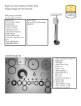
PowerBeamTM Pro
Electronic Trainer
User Guide
1
INTRODUCTION
Common Sense Precautions
Before starting any exercise program, consult with
your physician or health professional. He or she can
help establish the exercise frequency, intensity and
time appropriate for your particular age and condition. If you have any pain or tightness in your chest,
an irregular heartbeat, shortness of breath, feel faint,
or have any discomfort while you exercise, STOP!
Consult your physician before continuing. Failure to
follow any of these safeguards may result in injury or
serious health problems.
· Do not remove feet from pedals while cycling.
Congratulations! You’ve purchased the best electronic trainer available. With the CycleOps PowerBeamTM
Pro Trainer, you’ll be able to create personalized
training sessions to meet all your goals.
Never before has it been this easy to simulate the
conditions of a competition or event while in the
comfort of your home. The CycleOps PowerBeamTM
Pro’s electronic resistance unit (ERU) wirelessly communicates with the CycleOps PowerBeamTM Pro computer to provide exactly the resistance you want. A
target power based workout allows you to accurately
control your exercise intensity. A slope based workout allows you to relive your favorite ride without
leaving your home. Your workouts are automatically
recorded and can be downloaded to your computer
through CycleOps PowerAgentTM software (included
with your CycleOps PowerBeamTM Pro), so you can
create workouts and measure your progress.
This user guide will take you through setting up the
CycleOps PowerBeamTM Pro and thoroughly explains
how to use the CycleOps PowerBeamTM computer to
create workouts that will give you an edge over the
competition.
2
· Do not attempt to ride the bike at high RPM’s or in
a standing position until you have practiced at
lower RPM’s.
· Do not place fingers or any other objects into
moving parts of the trainer or bicycle.
· Keep children and pets away from your bike and
the trainer while in use. Do not allow children to
ride on your bike.
· Never turn pedal crank arms by hand. To avoid
entanglement and possible injury, do not expose
hands or arms to the drive mechanism.
· Do not dismount from your bike until both the
pedals and the rear wheel are at a complete STOP.
Part 1: Setting Up Your CycleOps PowerBeamTM Pro
(H)
(F)
(D)
(E)
(G)
(I)
(B)
(J)
(C)
(A)
1.1: Parts Listing
Your CycleOps PowerBeamTM Pro trainer should come with all of the following components:
•
•
•
•
•
•
•
•
•
•
•
Assembled CycleOps PowerBeamTM Pro Electronic Trainer resistance unit and frame (A)
Cadence sensor with battery installed (B)
Cadence sensor magnet with four (4) zip ties for cadence sensor (C)
Resistance unit power supply (D)
CycleOps skewer (E)
CycleOps PowerBeamTM Pro computer (F) with three (3) AAA batteries (installed)
CycleOps PowerBeamTM Pro computer handlebar mounting bracket (G)
Heart rate strap (H)
CD containing PowerAgentTM and Workout Creator software (I)
Race Day training DVD (J)
Warranty registration card (Not Shown) (you can also register your CycleOps trainer at www.cycleops.
com)
If you do not find all of these items in the box, please contact Saris customer service at 800-783-7257 (option 3).
3
1.2: Trainer Assembly
Next, insert the resistance unit power cable into the
resistance unit as shown below.
To begin assembling your trainer, extend the legs as
shown below, then set the trainer on a flat surface.
Se
Press
Extend
Plug the power supply into the wall outlet.
Turn the thumb wheel as shown below to level the
frame.
4
Use the zip ties to secure the cadence sensor to the
non-drive-side chain-stay of your bicycle as shown
below. Use additional zip ties to secure the magnet
to the crank arm directly across from the cadence
sensor. Be sure the magnet lines up with the line
on the sensor and that the magnet is no more than
3mm from the sensor.
1.3: Attaching your Bike to the Trainer
The CycleOps PowerBeamTM Pro trainer is designed
to be used with the provided skewer. Replace the
skewer on the rear wheel of your bike with the one
provided. Make sure the quick release handle is on
the left side of the bicycle and faces upward.
Pull the yellow cam lever down and rotate 90 degrees clockwise to unlatch the resistance unit. Pivot
the resistance unit down to allow clearance for your
rear wheel.
CAUTION: In this position the resistance unit can
move freely, keep fingers clear of moving parts.
Latch the resistance unit in a down position by rotating the cam lever 90 degrees counter clockwise and
push the cam lever against the resistance unit.
Rotate the yellow skewer clamp knob clockwise to
allow sufficient clearance for your skewer.
5
Lift your bike up by the seat post and insert the right
side (drive side) of the skewer into the fixed cone
on the corresponding side of the frame (as shown
below).
Align the left side of the skewer with the adjustable
cone, lining the notches in the cone up with the
quick release handle/lever. Rotate the yellow skewer
clamp knob as shown below to secure your rear
wheel into the trainer. Securely tighten the knob
until tightly in place.
The resistance unit should be tight enough to prevent the tire from slipping during accelerations.
A small indentation will be seen in the tire when
tightened properly. If slipping occurs, increase tire
compression by relatching the resistance unit. Pull
the yellow cam lever further down while performing
the initial unlatching step.
Note: Your bike does not need to be centered on the
roller for it to function properly.
Note: If the cam lever pops open while riding, move
the resistance unit and mount it to the front bolt
hole as shown below. Most tires will fit using either
mounting hole. Larger tires including 29” MTB tires
require mounting to the rear hole.
Pull the yellow cam lever down and rotate 90 degrees clockwise to unlatch the resistance unit. Push
the resistance unit towards your rear wheel until the
roller contacts the tire. Latch the resistance unit by
rotating the cam lever 90 degrees counter clockwise,
while holding the resistance unit. Compress the
roller against the tire by pulling up on the cam lever
as shown below.
Note: Be certain your tires are inflated to their proper
pressure. Knobby tires will cause noise and vibration.
For best results, use a slick-tread tire. Note that any
stationary trainer will increase the wear on your tires.
Using harder rubber composed tires will improve
their life.
Note: The CycleOps PowerBeamTM Pro trainer can be
used without the CycleOps PowerBeamTM Pro computer. Simply plug the resistance unit in and it will
provide a resistance curve similar to that of riding on
a flat road.
2
1.4: Attaching the CycleOps PowerBeamTM Pro computer to your Bike
TM
Attach the CycleOps PowerBeam Pro computer to
your bike by placing the bracket over the handlebars as shown below. Attach the straps to secure the
bracket to the handlebars.
The CycleOps PowerbeamTM Pro computer can be removed from the bracket by pushing it forward. Install
the optional screw to the underside of the bracket to
create a more permanent attachment.
1.5 Detaching your Bike from the Trainer
Pull the yellow cam lever down and rotate 90 degrees clockwise to unlatch the resistance unit. Pivot
the resistance unit down to allow clearance for your
rear wheel. Latch the resistance unit by rotating the
cam lever 90 degrees counter clockwise and pushing
up.
Hold your bike by the seatpost. Rotate the yellow
skewer clamp knob counter clockwise to release
your bike.
3
Part 2: Navigating the CycleOps PowerBeamTM Pro computer
The CycleOps PowerBeamTM Pro computer enables
you to track all aspects of your workout and customize them to your individual needs.
The CycleOps PowerBeamTM Pro computer features
a display and four buttons. The mode button allows
you to access a number of different functions within
the display. The arrow buttons enable you to toggle
up and down between functions or adjust the resistance level. The select button chooses the function.
To turn the CycleOps PowerBeamTM Pro on, push any
button. The display then offers three different modes
for you to choose. Use the arrow buttons to highlight
the mode you want, and then press select to choose
it. Each mode is described in-depth in its own section.
Part 3: Ride Mode
Ride Mode allows you to set the individual levels of
your workout while it’s in progress. It does not follow
a pre-programmed workout.
3.1: Ride Mode Display
When you enter Ride Mode, the unit automatically
finds the resistance unit and sensors. After a moment, the display will show a screen like the one
below.
The screen is divided into six boxes, each of which
tracks a different aspect of the workout. The active
box is highlighted with solid lines. When a box is
active, you can make adjustments to it by pressing
select. Press the mode button to toggle between
the six boxes. To return to the main menu (see Part
2), press and hold mode and select together for two
seconds.
4
3.2: Level
The level is measured in one of two ways, slope or
watts. Slope measures grade steepness of your simulated climb. Watts sets a target power output for you
to meet. To switch between slope and watts, press
the select button while the level box is highlighted.
You can choose a grade between 0 and 10 for the
slope. The higher the number, the steeper the slope
you’re climbing. Use the arrow buttons with any box
active to increase or decrease the slope.
While in slope mode, the trainer provides the resistance for the selected slope at whatever speed
you’re riding. The faster you pedal, the more resistance you’ll need to overcome, just like riding up an
actual hill. The resistance the CycleOps PowerBeamTM
Pro simulates the power needed for a 176 lb. bike
and rider to climb the slope on a road bike with slick
tires. You can adjust the weight and the bike options
using PowerAgentTM software.
torso just below the pectoral muscles as shown in
the picture below.
While in watts mode, target power can be adjusted
between 30 and 1000 watts in 10-watt increments.
Use the arrow buttons with any box active to increase or decrease the number of watts.
TM
The CycleOps PowerBeam Pro automatically adjusts the resistance to match the target power
output. Power is a combination of speed and torque.
Because of this, you experience less resistance the
faster you pedal, keeping your power output at the
desired level. This enables you to customize your
workout to meet specific performance needs.
Note: Not all power levels are available at all speeds.
When the CycleOps PowerBeamTM Pro cannot add
any more resistance, an up arrow is shown in the
speed/cadence box to indicate you should speed up
to achieve the target power. When the CycleOps PowerBeamTM Pro cannot remove any more resistance
a down arrow is shown in the speed/cadence box to
indicate you should slow down to achieve the target
power.
3.3: Power
The number displayed in the Power box in watts is
the measurement of the power you are expending.
Press select to view the average power in watts of
your workout, and press it again to view your maximum wattage. Press it once more to display total
kilojoules and once again to return to current power.
3.4: HR
HR displays your heart rate during the workout. You
must be wearing the heart rate monitor strap for
this box to function. Pressing select will enable you
to see your average heart rate over the course of
the workout. Pressing it again shows your maximum
heart rate. Press it once more to return to current
heart rate.
For best results, moisten the contacts. The monitor will communicate wirelessly with the CycleOps
PowerBeamTM Pro computer while you ride. The
CycleOps PowerBeamTM Pro computer automatically
finds for your heart rate strap when a workout is
entered. Once it is found, the data is displayed on the
CycleOps PowerBeamTM Pro computer. If the strap
is not found, the unit will time out and stop searching. If you attach your heart rate strap while a ride is
in progress, exit and enter the ride to re-initiate the
search.
Note: When the battery is changed out in the heart
rate strap, you will need to re-learn the device to the
CycleOps PowerBeamTM Pro computer (see Section
5.5).
3.5: Interval
Your ride can be broken into sections called “intervals” by pressing and releasing the mode and select
buttons at the same time. The interval box displays
which section of the workout you are currently in.
Press select while the interval box is highlighted to
enter active interval mode. This causes the screen to
darken and display information for the active interval only, as shown below. While in active interval
mode, press mode to cycle between the six boxes on
the screen. Press select to cycle through the parameters normally shown in that box. The values shown
are only for the interval you’re currently in.
3.4.1: Using the Heart Rate Monitor Strap
Before beginning your ride, place the strap on your
5
Press select while the interval box is highlighted to
go to the “interval memory” mode.
The screen remains dark, and you’ll be able to check
the results of previous intervals in your ride. The
word, “memory,” appears below the interval number
to indicate you are in interval memory mode.
it is found, the data is displayed on the CycleOps
PowerBeamTM Pro computer. If none is found, the unit
will time out and stop searching. If you attach your
cadence sensor in the middle of a workout or ride,
exit and enter the ride to re-initiate the search.
Note: When the battery is changed out in the cadence sensor, you will need to re-learn the device to
the CycleOps PowerBeamTM computer (see Section
5.5).
3.7: Time
This box displays your total ride time. You can also
choose to display distance by pressing the select
button.
3.8 Exiting a Ride
While in “active interval” or “interval memory” mode,
the power is always the power you’re currently
expending. Return to the normal ride screen by
pressing select while the interval box is highlighted.
You will return to your normal ride after you cycle
through your intervals.
If you want to take a break, press and hold the mode
and select buttons for two seconds. You will be taken
to the “Ride Option” screen.
Note: Your ride data, including time and all average
calculations, will be paused.
3.6: Cadence/Speed
“Cadence” displays the number of RPM’s you’re pedaling and is measured by the cadence sensor on your
bicycle frame. You can press select to display the
average cadence or maximum cadence.
This box can also be used to display your speed.
Press select until you see “SPD MPH” or “SPD KPH.”
The CycleOps PowerBeamTM Pro computer now
monitors your current speed in miles per hour/kilometers per hour. Pressing select again will measure
your average speed, and pressing it one more time
will give you your maximum speed. Press select once
more to return to cadence.
3.6.1 Using the Cadence Sensor
You must install the cadence sensor if you want to
monitor your cadence during the ride. Refer to Part 1
for installation instructions. The cadence sensor will
communicate wirelessly with the CycleOps PowerBeamTM Pro computer while you ride. The CycleOps
PowerBeamTM Pro computer automatically finds your
cadence sensor when a workout is entered. Once
6
Press “Resume” to return to the ride. “Exit” leaves the
ride and returns to the main menu. The current ride
status, data, and time are saved and can be resumed
from this point. “Find” returns to the ride and re-initiates the search for heart rate and cadence sensors.
Part 4: Workout Mode
Workout Mode enables you to put together a program designed for your specific training needs.
You can choose one of the pre-loaded workouts,
or you can create your own customized workout
with PowerAgentTM and upload it into the CycleOps
PowerBeamTM Pro computer (see PowerAgentTM User
Guide).
4.1 Choosing a Workout
From the Main Menu, select “Workouts.” You’ll see a
screen that offers a number of workouts, including
any you have saved to the CycleOps PowerBeamTM
Pro computer. Use the arrow buttons to highlight the
workout you want, and press select to choose it.
4.3: Power
This box displays your current power output in watts.
(See Section 3.3 for more detail).
4.4: HR
This box displays your current heart rate. (See Section 3.4 for more detail).
4.5: Workout
You’ll be taken to the Workout Mode screen. This
screen displays similar information to the Ride Mode
screen (see Part 3). Your workout will begin as soon
as you start pedaling. It is divided into six boxes, each
of which displays a different part of your workout.
The active box is highlighted with solid lines around
it. When a box is active, you can make adjustments to
it or change what it displays. Use the mode button to
toggle between boxes.
This box displays two things, a countdown to the
next segment and the current segment number.
The countdown displays either the time or distance,
depending on how the workout was set up in PowerAgentTM.
4.2: Level
Note: Interval functions are deactivated in Workout
Mode.
Like in Ride Mode, this box displays the slope of the
grade for the interval or its target power in watts
However, you cannot toggle between the two like
you can in Ride Mode. Slope or watts is set when
the workout is created. You can, however, increase or
decrease the slope or the target power by using the
arrow buttons.
To skip ahead to the next segment in the workout,
press and hold the mode and select buttons together for one second.
4.6: Cadence
Cadence displays the number of RPM’s you’re pedaling. (See Section 3.6 for more detail).
4.7: Time
This is the total elapsed time of your workout. (See
Section 3.7 for more detail).
7
4.8: Exiting a Workout
If you need to take a break, press and hold the mode
and select buttons together for two seconds. You will
be taken to the “Ride Options” screen.
Press “Resume” to return to the workout. “Exit” leaves
the workout and returns to the main menu. The current workout status, data, and time are saved and can
be resumed from this point. Note that only the last
workout’s status is saved and can be resumed. Other
workouts must be started from the beginning of the
workout. “Find” returns to the ride and re-initiates the
search for heart rate and cadence sensors.
Part 5: Setup Mode
Setup Mode enables you to set several options on
the CycleOps PowerBeamTM Pro . You can calibrate
your devices, work with memory, and change many
other features of the system. Choose “Setup” from
the Main Menu by using the arrow buttons to highlight it and then pressing select to enter Setup Mode.
5.1: Setup Screen
When you first enter Setup Mode, you will see a
screen that presents you with several options. Use
the arrow buttons to scroll down to the option you
want and press select to choose it. Each option is
explained in detail in the following sections.
8
5.2: Memory
This option allows you to work with the available
memory in your CycleOps PowerBeamTM Pro computer. There are two choices on this screen.
•
•
“Remaining” indicates how much space is left
to store ride data. The CycleOps PowerBeamTM Pro
comes with enough room to store about 15 hours of
ride information. “Clear Ride Data” deletes all stored
rides on the CycleOps PowerBeamTM Pro computer.
Make sure you no longer need a ride or have downloaded it to your computer before choosing “Clear”.
Only the ride data is cleared; workouts uploaded
from PowerAgentTM, calibration information and
odometer data are still stored.
Clamp the resistance unit to the rear tire according to the instructions in this guide (see Section
1.3).
For mountain bicycles, use smooth tires. Knobby
tires are noisy and contribute to inaccuracies.
5.3.1 Roll Down Calibration
1. Before entering the calibration routine, warm up
the CycleOps PowerBeamTM Pro and tires by riding the system for five minutes.
2. From the main menu, choose Setup Mode.
3. From the setup menu, choose Calibration.
4. From the calibration menu, choose Roll Down
Calibration.
5. The CycleOps PowerBeamTM Pro computer will instruct you to pedal to 18 mph. Your current speed
is displayed as well.
“Odometer” displays the total number of miles (or
kilometers) you have ridden on the CycleOps PowerBeamTM Pro trainer.
5.3 Calibration
The CycleOps PowerBeamTM Pro resistance unit is
calibrated at the factory. This enables it to accurately
measure power using similar technology to a power
meter. Rolling resistance is calibrated into the each
individual unit, but can vary depending on tire type,
tire pressure, clamping pressure and other conditions. To obtain the most accurate results, follow the
subsequent guidelines:
• Perform either the Roll Down Calibration or
Manual Calibration described below.
• Inflate tires to the rated pressure.
• Attach the bicycle according to the instructions
in this guide (see Section 1.3).
6. Once at 18 mph, hold this speed for two minutes.
A count down timer displays your remaining
time.
7. After two minutes, immediately stop pedaling
and allow the system to coast to a complete stop.
8. Do not touch or disturb the resistance unit while
the system is coasting. Do not pedal while the
system is coasting. Do not hit the brakes.
9. After the unit comes to a complete stop, the
CycleOps PowerBeamTM Pro computer will display “Calibration Passed.” If you do not wait the
full two minutes or another issue occurs during
calibration, the CycleOps PowerBeamTM Pro computer will display “Calibration Failed.” If calibration fails, repeat the calibration. If it continues to
fail, contact Saris Cycling Group.
10. The unique rolling resistance calibration is now
incorporated into the factory calibration. This
calibration will remain in the system until another calibration is performed.
9
5.3.2 Manual Calibration
5.4: Options
This choice allows you to customize the CycleOps
PowerBeamTM Pro computer display. Use the arrow
buttons to scroll down to the option you desire and
press select to choose it.
If you own a PowerTap power meter, you can perform a manual calibration to more accurately calibrate your CycleOps PowerBeamTM Pro trainer. Attach
the power meter to your handlebars so you can read
both the PowerTap CPU as well as the CycleOps PowerBeamTM computer.
1. Before entering the calibration routine, warm
up the CycleOps PowerBeamTM Pro by riding the
system for five minutes.
2. From the main menu, choose Setup Mode.
3. From the setup menu, choose Calibration.
4. From the calibration menu, choose Manual Calibration.
5. The CycleOps PowerBeamTM Pro computer displays the measured power using the current
rolling resistance calibration. Pedal at a constant
speed to stabilize the resistance. Target 20 mph.
6. Use the up and down arrow buttons to adjust the
calibration until the displayed power matches
your PowerTap CPU. Pressing the up arrow button will increase the measured power while
pressing the down arrow button decreases the
measured power.
7. When the two values match, press mode or select
to exit the calibration.
8. The unique rolling resistance calibration is now
incorporated into the factory calibration. This
calibration will remain in the system until another calibration is performed.
Note: The Roll Down Calibration and the Manual Calibration adjust the same calibration values. Only the
last calibration values are held in memory.
10
5.4.1: Time/Date
This option allows you to set the time and date.
5.4.1.1: 12-24 Clock
Choose between displaying a 12 or 24 hour clock.
5.4.1.2: Time
Use the arrow buttons to increase or decrease the
time. Use the select button to choose hours or minutes.
5.4.1.3: Date
Use the arrow buttons to increase or decrease the
date. Use the select button to step through the
month, day or year.
5.4.2: Backlight
This option enables you set when the display’s backlight will come on. Use the arrow buttons to choose
the option you like best and press select to choose it.
“UI Data” turns the backlight on when data is received from the resistance unit or when buttons are
pressed on the CycleOps PowerBeamTM Pro computer. “UI” turns the backlight on only when buttons
are pressed. “OFF” never turns backlight on. Note that
your batteries will have a longer life when the backlight is used less.
5.4.3 Sleep Time
This function allows you to set the amount of time
the CycleOps PowerBeamTM Pro computer waits
without any activity before it goes into power-saving
sleep mode. Use the arrow buttons to increase or
decrease the number of minutes and press select to
choose it. Again, a shorter time before entering sleep
mode results in increased battery life.
5.4.4: MPH-KPH
This option allows you to choose how you would like
the speed and distance displayed. You can
choose English (miles and miles/hour) or metric
(kilometers and kilometers/hour). Use the arrow
buttons to highlight the units you prefer and press
select to choose it.
the battery in the sensor before activating the learn
2 process. After the battery is re-inserted there is
only a 2 minute window to pair using learn 2.
The resistance unit learn function has the same basic
logic as above, but only offers learn 2 to avoid having
two CycleOps PowerBeamTM Pro computers controlling a single resistance unit.
To pair a CycleOps PowerBeamTM Pro computer and
resistance unit, simply use learn 2. The power to the
resistance unit must be cycled by unplugging the
unit from the electrical supply.
The CycleOps PowerBeamTM Pro computer also has
an automatic learn 2 function for the resistance unit.
When the “Resist Unit” ID is set to zeros (00000), the
CycleOps PowerBeamTM Pro computer will automatically pair to the first available resistance unit after
entering the ride or workout screen.
Note: When the battery is removed and re-inserted in
the heart rate strap or the cadence sensor, you must
re-learn them to the CycleOps PowerBeamTM Pro computer . Changing the battery resets the strap.
5.5: Device ID
Pressing “Reset” will reset all the device IDs to zeros.
This option allows you to manually set which devices
are paired to the CycleOps PowerBeamTM Pro computer. A unique number identifies which resistance
unit, chest strap, and cadence sensor is currently
paired with the CycleOps PowerBeamTM Pro computer. Use the arrow buttons to highlight the options
and press select to choose it.
For each of the devices, (i.e., resistance unit, chest
strap and cadence sensor) you can manually enter
the ID number. Use the arrow buttons to enter the
number and the select button to go to the next character. After the last character, the “learn” modes are
displayed. With the learn mode flashing, press and
hold select to perform the function. When a device is
found, the unique ID is displayed.
There are two learn options for the chest strap and
cadence sensor. Learn 1 is used when you have a
new sensor or CycleOps PowerBeamTM Pro computer
and there are no like sensors within a 30 foot radius.
Learn 2 is used if there are other like devices in the
area. Note this requires you to remove and re-insert
5.6: Test
This option allows you to perform tests on your
CycleOps PowerBeamTM Pro unit to help determine
operational status. Use the arrow buttons to scroll
down to the option you desire and press select to
choose it.
5.6.1 About
This screen displays the version number for the
firmware running on the CycleOps PowerBeamTM Pro
computer and the Saris Cycling Group customer ser11
vice telephone number. Press any button to return
to the Test menu.
5.6.2 LCD Test
The LCD test performs a test of the CycleOps PowerBeamTM computer ’s LCD to demonstrate that each
pixel on the screen can turn on and off. Press any
button to return to the Test menu.
5.6.3 Backlight
Choosing backlight will temporarily turn the backlight on. Press any button to return to the Test menu.
5.6.4 Transmit Test
The transmit test performs a test of the CycleOps
PowerBeamTM computer transmitter. Press any button to return to the Test menu.
5.6.5 ERU Data
Displays raw data coming from the resistance unit.
“Roller Speed” displays the current rotational speed
of the roller. The number displayed represents the
number (R) of 32 microsecond counts for the latest
roller rotation. 11156/R converts the roller speed to
miles per hour. “Raw Analog” displays the voltage on
the strain gauge used to measure power. “ERU Version” displays the version number for the firmware
running on the resistance unit.
12
Warranty
Procedures
The CycleOps PowerBeamTM Pro is designed specifically for home use and as such carries the following
warranty:
Warranty service will be performed by Saris Cycling
Group or an authorized Saris Cycling Group Dealer.
The original purchaser must provide proof of purchase. Service calls and/or transportation to and
All Saris Cycling Group CycleOps PowerBeamTM Pro
from the Authorized Saris Cycling Group Dealer are
products are warranted to the original retail purchas- the responsibility of the purchaser.
er to be free from defects in materials and workmanship. Warranty coverage valid to the original purchas- 1. Saris Cycling Group will have the option to repair
er only and proof of purchase will be required.
or replace any product(s) which requires warranty service.
Residential Environment:
2. Saris Cycling Group will replace any unit that is
Frame: Lifetime
structurally defective with a new unit or replace
Electronics: 1 year
the unit with a unit of equal value.
3. In the event a product cannot be repaired, Saris
This warranty excludes wear items that need to be
Cycling Group will apply a limited credit reimreplaced due to normal wear and tear.
bursement toward another CycleOps PowerBeamTM Pro Trainer product of equal or greater
This warranty does not cover:
value.
1. Normal wear and tear.
2. Any damage, failure or loss caused by accident,
misuse, neglect, abuse, improper assembly, improper maintenance, or failure to follow instructions or warnings in Owner’s Manual.
3. Use of products in a manner or environment for
which they were not designed.
Limitations
The foregoing warranties are in lieu of and exclude
all other warranties not expressly set forth herein,
whether expressed or implied by operation of law or
otherwise, including, but not limited to, warranties
of merchantability or fitness for a particular purpose.
Saris Cycling Group shall in no event be liable for
incidental or consequential losses, damages or expenses in connection with its exercise products. Saris
Cycling Group’s liability hereunder is expressly limited to the replacement of goods not complying with
this warranty or, at Saris Cycling Group election, to
the repayment of an amount of the purchase price of
the exercise product in question. Some states do not
permit the exclusion or limitation of implied warranties or incidental or consequential damages, so the
preceding limitations and exclusions may not apply
to you.
Saris Cycling Group, Inc.
5253 Verona Rd.
Madison, WI 53711
800-783-7257
www.saris.com
www.cycleops.com
13
Statement of Compliance for FCC and
Industry Canada:
Saris Cycling Group, Inc.
Model #: Power Beam
Model #: Computer+
Contains FCC ID: T8P-SL24TT1
IC: 6459A-SL24TT1
“This device complies with Industry Canada and Part
15 of the FCC Rules. Operation is subject to the following two conditions:
(1) This device may not cause harmful interference,
and
(2) this device must accept any interference received,
including interference that may cause undesired
operation.”
The term “IC:” before the radio certification number
only signifies that Industry Canada technical specifications were met.
Changes or modifications to this device not expressly approved by the party responsible for compliance
with FCC regulations (the manufacturer) could void
the user’s authority to operate the equipment.
This equipment has been tested and found to comply with the limits for a Class B digital device, pursuant to part 15 of the FCC Rules. These limits are
designed to provide reasonable protection against
harmful interference in a normal installation. This
equipment generates, uses and can radiate radio
frequency energy and, if not installed and used in
accordance with the instructions, may cause harmful interference to radio communications. However,
there is no guarantee that interference will not occur
in a particular installation.
Saris Cycling Group, Inc.
5253 Verona Rd.
Madison, WI 53711
800-783-7257
www.saris.com
www.cycleops.com
17946a 07/08
14