1
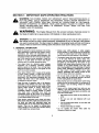
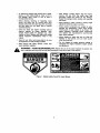
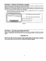
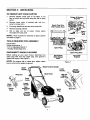
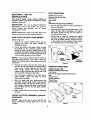
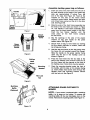
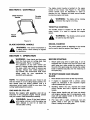
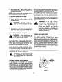
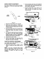
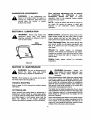
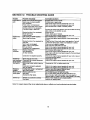
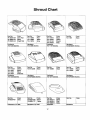
OPERATOR'S
MANUAL
Model Series
410 thru 429
Model 428C Shown
IMPORTANT:
READ SAFETY
RULES AND INSTRUCTIONS
CAREFULLY
Warning:
This unit is equipped with an intemal combus_on engine and should not be used on or near any unimproved forestcovered, brush-covered or grass-covered land unless the engine's exhaust system is equipped with a spark an'ester meeting
applicable local or state laws (if any). If a spark an'ester is used, it should be maintained in effecfiye working order by the operator.
In the State of California the above is required by law (Section 4442 of the California Public Resources Code). Other states may have
similar laws. Federal laws apply on federal lands. A spark arrester for the muffler is available through your nearest engine authodzed
service dealer or contest the service department, P.O. Box 368022 Cleveland, Ohio 44136-9722.
MTD PRODUCTS
PRINTED IN U.S.A.
INC. P.O. BOX 368022 CLEVELAND,
OHIO 44136-9722
FORM NO. 770-1026B
(9970909)
SECTION
1: IMPORTANT
SAFE OPERATION
PRACTICES
NOT FOLLOWED,
PERSONAL SAFETY
SAFETY INSTRUCTIONS
AND/OR PROPERTY
WARNING:
THIS COULD
SYMBOL ENDANGER
POINTS OUTTHEIMPORTANT
WHICH, OF
IF
,_
YOURSELF
AND OTHERS.
READ AND FOLLOW ALL INSTRUCTIONS
IN THIS MANUAL
BEFORE A'I-I'EMPTING
TO OPERATE YOUR_ LAWN MOWER. FAILURE TO COMPLY WITH
THESE
INSTRUCTIONS
MAY RESULT
IN PERSONAL
INJURY. WHEN
YOU SEE THIS
SYMBOL, HEED ITS WARNING:
WARNING:
The Engine Exhaust from this product contains chemicals
the State of California to cause cancer, birth defects or other reproductive harm.
&
known to
DANGER: Your lawn mower was built to be operated according to the rules for safe operation in
this manual. As with any type of power equipment, carelessness or error on the part of the operator
can result in serious injury. This lawn mower is dapable of amputating hands and feet end throwing
objects. Failure to observe the following safety instructions could result in sedous injury or death.
1. GENERAL
OPERATION
• Read this operator's manual carefully in its entirsty
before attempting to assemble this machine. Read,
understand, and follow all instructions on the
machine and in the manual(s) before operation.Be
completely familiar with the controls and the proper
use of this machine before operating it. Keep this
manual in a safe place for future and regular
reference and for ordedng replacement parts.
Always wear safety glasses or safety goggles
during operation or while performing an adjustment
or repair, to protect eyes from foreign objects that
may be thrown fromthe machine in any direction.
Thoroughly inspect the area where the equipment
is to be used. Remove all stones, sticks, wire,
bones, toys and other foreign objects which could
be picked up and thrown by the mower in any
direction and cause sedous pereonal injury to the
operator or any others allowed in the area. Plan
your mowing pattern to avoid dischargeof matedal
toward reads, sidewalks, bystanders and the like.
To help avoid a thrown objects injury, keep
children, bystanders and helpers at least 75 feet
from the n_owerwhile it is in operation.
• Your rotary mower is a precision piece of power
equipment, not a plaything. Therefore, exercise
extreme caution at all times. Your unit has bean
designed to perform one job: to mow grass. Do not
use it for any other purpose.
• Never allow children under 14 years old to operate
s power mower. Children 14 years old and over
should only operate mower under close parental
supervision. Only responsible Individuals who are
familiar with these rules of safe operation should
be allowed to use your mower,
•
Do not put hands or feet :near or under rotating
parts. Keep clear of discharge opening at all times
as the rotating blade can cause injury.
• Many injudos occur as a result of the mower being
puffedover the foot during a fall. Do nothang on to
the mower if you are falling; release the handle
immediately.
• Keep the area of operation clear of all persons,
particularly small children and pets. Stop engine
when they are in the vicinity of your mower to help
prevent blade contact or thrown object injury.
Although the area of operation should be
completely cleared of foreign objects, an object
may have been overlooked and could be
accidentally thrown by the mower in any direction
and cause sedous personal injury to the operator
or any others allowed in the area.
• Never pull the mower toward you while you are
walking. If you must back the mower away from a
wall or obstructionfirst look down and behind, and
then follow these steps:
• Wear sturdy, rough-soled work shoes and closefittingslacks and shirts. Shirts and pants that cover
the arms and legs an_l steal-toed shoes are
recommended. DO not wear loose fitting clothesor
jewelry. They can be caught in moving parts.
Never operate a unit in bare feat, sandals, slippery
or lightweight (e.g. canvas) shoes.
•
Step back from the mower to fully extend your
arms,
•
Be sure you are well balanced with sure
footing.
•
Pull the mower bank slowly, no more than haft
way toward you.
Repeat these steps as needed.
• Do not operate the mower
influence of alcoholor drugs.
2
while under the
•
Do not engage the self-propelled mechanism on
units so equipped while starting engine.
•
• The blade control handle is a safety device. Never
attempt to bypass its operation. Doing so makes
the safety device inoperative and may result in
personal injury through contact with the rotating
blade. The blade control handle must operate
easily in both directions and automatically return to
the disengaged position when released.
•
Mow only in daylight or good artificial light.
•
Stop the blade when crossing gravel drives, walks
or roads.
•
If the equipment should start to vibrate abnormally,
stop the engine and check immediately for the
cause. Vibration is generally a waming of trouble.
•
DO NOT:
Never operate the mower in wet grass. Always be
sure of your footing. A slip and fall can cause
serious personal injury. Keep a firm hold on the
handle and walk, never run. If you feel you are
losing your footing,
RELEASE
THE BLADE
CONTROL
HANDLE
IMMEDIATELY
and the
blade will stop rotating within three seconds.
•
•
Muffler and engine become hot and can cause a
bum. Do not touch.
Do not mow slopes greater than 15 degrees as
shown on the slope gauge.
•
Do not mow on wet grass. Reduced footing could
cause slipping.
•
Keep children out of the mowing area and under
the watchful care of a responsible adult other than
the operator.
Be alert and turn mower off if a child enters the
area.
•
Before and while moving backwards, look behind
and down for small children or other objects.
Never allow children under age 14 to operate the
mower. Children 14 years of age and above
should read and understand the operation
instructions and safety rules in this manual.
•
Use extreme care
when approaching blind
corners, shrubs, trees, or other objects that may
obscure your vision of a child or hazard.
4. SERVICE
Use extreme care in handling gasoline and other
fuels. They are extremely flammable
and the
vapors are explosive.
• If situationsoccur which are not covered in this
manual, use care and good judgment. Contact
your dealer for assistance. Telephone 1-800-8007310 for the name of your nearestdealer.
Use only an approved gasoline container.
Never remove gas cap or add fuel while the engine
is running. Allow engine to cool at least two
minutes before refueling.
OPERATION
Replace gasoline cap securely and wipe off any
spilled gasoline before starting the engine as it
may cause a fire or explosion.
For your safety, use the slope gauge included as part of
this manual to measure slopes before operating this unit
on a sloped or hilly area. If the slope is greater than 15
degrees as shown on the slope gauge, do not operate
this unit on that area or serious injury could result.
Extinguish all cigarettes, cigars, pipes and other
sourcesof ignition.
Never refuel machine indoorsbecause flammable
vaporswill accumulatein the area.
DO:
•
•
•
• Only use accessories approved for this machine
by the manufacturer.Read, understand,and follow
all instructions provided with the approved
accessory.
2. SLOPE
Do
not mow
near
drop-offs,
ditches or
embankments. The operator could lose footing or
balance.
Tragic accidents can occur if the operator is not alert to
the presence of children. Children are often attracted to
the mower and the mowing activity. Never assume that
children will remain where you last saw them.
engine is shut off. Never place any part of the body
in the blade area until you are sure the blade has
stopped rotating.
Never operate mower without proper guards, grass
catcher, plates or other safety protective devices in
place.
•
3. CHILDREN
Shut the engine off and wait until the blade comes
to a complete stop before removing the grass
catcher or unclogging the chute. The cutting blade
continues to rotate for a few seconds after the
•
Atways be sure of your footing. A slip and fall can
cause serious personal injury. If you feel you are
losing your balance release the blade control
handle immediately and the blade will stop in less
than 3 seconds.
Mow across the face of slopes; never up and
down. Exercise extreme caution when changing
direction on slopes.
Never store the machine or fuel container inside
where there is an open flame or spark such as a
gas water heater, space heater, or fumace.
• Watch for holes, ruts, hidden objects, or bumps.
Tall grass can hide obstacles.
Never run an engine inside a closed area.
3
• To reduce fire hazard, keep mower free of grass,
leaves, or other debris build-up. Clean up oil or
fuel spillage. Allow mower to cool at least 5
minutes before stodng.
After stdking a foreign object, stop the engine,
remove the wire from the spark plug, and
thoroughly inspect the mower for any damage.
Repair the damage before starting and operating
the mower.
• Before cleaning, repairing, or inspecting, make
certain the blade and all moving parts have
stopped. Disconnectthe spark plug wire, and keep
the wire away from the spark plug to prevent
accidentalstarting.
•
Check the
blade and engine
mounting
Never attempt to make a wheel or cutting height
adjustmentwhile the engine is running.
Grass catcher components are subject to wear,
damage and detsdorstion, which could expose
moving parts or allow objects to be thrown. For
safety protection, frequently check components
and replace with manufacturer's recommended
parts, when necessary.
bolts at
frequent
intervals for proper tightness.
Also,
visually inspect blade for damage
(e.g., bent,
cracked or worn). Replace with blade which meats
odginal equipment
specifications
listed in this
manual
•
• Keep all nuts, bolts, and screws tight to be sure
the equipment is in safe working condition.
• Do not change the engine governor setting or
overspeed the engine. Excessive engine speeds
are dangerous.
• Never tamper with safety devices, Check their
properoperation regulady.
&
Mower blades are sharp and can cut. Wrap the
blade(s) or wear gloves, and use extra caution
when servicing them.
WARNING
- YOUR RESPONSIBILITY:
Restrict the use of this power machine to persons who
read, undemtand and follow the warnings and instructionsin this manual and on the machine.
DANGER
Figure 1 Safety Labels FoundOn Lawn Mower
4
SECTION
2: FINDING YOUR MODEL NUMBER
This Operator's Manual is an important part of your new walk behind. It will help you assemble, prepare and
maintain your walk behind. Please read and understand what it says.
Before you start to prepare your walk behind for its first use, please locate the model plate and copy the
information from it in this Operator's Manual. The information on the model plate is very important if you need
help from your dealer or the MTD customer support department.
• Every walk behind has a model plate. You can locate it by standing behind the unit in the operating
position and looking down at the rear of the deck.
• The model plate will look like Figure 2
r
This is where your model number will be.
[
XXX-X-XXX-X-XXX
XXXXXXXXXXX
This is where your serial number will be.
Copy the model number here:
MTD PRODUCTSINC
CLEVELAND,
OHIO44136
Copy the serial number here:
Figure 2
SECTION
3: CALLING
CUSTOMER
SUPPORT
If you are having difficulty assembling this product or if you have any question regarding the controls,
operation or maintenance of this unit, please call the Customer Support Department. You can reach them by
calling:
1-800-800-7310
Before you call, make sure that you have your model and serial numbers ready. By having the model and
serial numbers ready, you help the Customer Support Representative give you faster service. To find your
unit's model and serial number, see SECTION 2: FINDING YOUR MODEL NUMBER.
5
USE THIS PAGE AS A GUIDE TO DETERMINE SLOPES WHERE YOU MAY NOT OPERATE SAFELY.
SIGHT AND HOLD THIS LEVEL WITH A VERTICAL TREE
|q
A POWER POLE
I
A CORNER OF A BUILDING
OR A FENCE POST
I
I
o
m
O_
¢)
¢)
rrl
lbwARNING
Do not mow on inclineswith a slope in excess of 15 degrees (a rise of approximately2-1/2 feet every 10 feet). A riding mower
could overturnand cause serious injury. If operating a walk-behind mower on such a slope, it is extremely difficultto maintain
yourfooting and you could slip, resultingin sedous injury.
Operate RIDING mowersup and downslopes, never across the face of slopes.
Operate WALK-BEHIND mowers acrossthe face of slopes, never up and down slopes.
SECTION
4" UNPACKING
TO REMOVE
UNIT FROM CARTON
I.
Remove staples, break glue on top flaps, or cut
tape at carton end and peel along top flap to open
carton.
2.
Remove loose parts if included with unit (i.e.,
owner's manual, etc.).
3.
Cut along dotted lines and lay carton down flat.
4.
Remove packing material.
5.
Roll or slide unit out of carton. Check carton
thoroughly for loose parts.
Brigg..s&.Stratton
_ng,nes
v.s,ot.
Spark Plug Wire
With Rubber Boot
_ _,_'T_
Q
\
/\
Plug
Wire
NOTE: Parts included for assembly of grass catcher
are listed on page 8.
TOOLS
REQUIRED
i_on Engine_
Retaining
Post,
FOR ASSEMBLY
_ _park
Pair of Pliers
Phillips Screwdriver t
7/16" or Adjustable Wrench 1"
1"Hardtop Grass Bags Only.
DISCONNECT
SPARK
Spark Plug
PLUG WIRE
Spark Plug Wire
Before setting up your lawn mower, disconnect the
spark plug wire from the spark plug, and ground it
against the engine. See Figure 3.
All Engines
With Rubber
Boot
NOTE: On engines with a rubber boot, attach rubber
Tecumseh
Engines
Fi lure 3
boot to a bolt on the engine to ground.
Upper
Blade Control Handle
Lower
Handle.._
Hand Knob
Spark
Handle
Mounting
Bracket
Figure 4
7
-.\
Hair Pin
In
Handle
Mountin(I
Bracket"
SOFT GRASS
SECTION 5" SET-UP
INSTRUCTIONS
This owner's guide covers various models of
mowers. Follow only those instructions which
pertain to your unit.
IMPORTANT:
This unit is shipped WITHOUT
GASOLINE or OIL in the engine. Be certain to
service engine with gasoline and oil before
operatingyour mower.
(Models410 thru 418)
Parts for Soft Grass Bag:
Front Frame
Rear Frame
Bag
Assemble soft grass bag as follows:
1. Jointhe rear frame and front frame assembly as
shownin Figure5A.
2.
Place bag over frame (black plastic side is the
bottomof bag). Slip the openings in the side of
the plastic channel on bag over the hooks on
the grass catcher frame.
3.
Secure bag to frame by woddng the plastic
channels on bag over frame as shown in Figure
5B. All of the plasticchannels except center top
of bag attach from the outside of bag. Center
topof bag attaches from the inside of bag.
NOTE: Reference to right or left hand side of the
mower is obsewed from the operating position.
HOWTO
SET-UPYOUR
LAWN
MOWER
(Refer to Figure4)
1.
2.
Remove any packing material which may be
between the upper and lower handles for
shippingpurposes.
Pull up and back on the upper handle to raise
the handle into the operating position. Make
certain the lower handle is seated securely into
the handle mounting brackets. Tighten the hand
knobson each side of the handle (cerriage bolts
mustbe seated propedyintothe handle).
Frame
Assembly
NOTE: Your mower is shipped with the handle in
the higher height position. If you wish to lower the
height of the handle, refer to the AdjustmentSection
at this time.
3.
Remove the hairpin clips from the outer hole in
the weld pins on the handle mounting brackets.
Using a pair of pliers, squeeze one leg of the
lower handle against the handle mounting
bracket. Insert the hairpin clip into the inner hole
on the weld pin. Repeat on other side,
4.
The rope guide is attached to the dght side of
upper handle. Loosen the wing nut which
securesthe rope guide.
5.
With the spark plug wire disconnected and
grounded, hold the blade control handle against
the upper handle, and pull the starter rope out
of the engine. Release the blade controlhandle.
Slip the starter rope into the rope guide,Tighten
the wing nut.
6.
BAG
-._ Rear
Frame
Plastic
Channels
Figure5
HARDTOP
GRASS
BAG
(Models 420 thru 428)
Parts for Hardtop Grass Beg:
Front Frame
Rear Frame (packed inside hardtopcover)
Bag
HardtopCover
MountingBracket
PhillipsScrew
Hex LockNut
, Slit
Make certain ell nuts and bolts are tightened
securely.
GRASS CATCHER ASSEMBLY (Optional
Equipment)
Rear
Frame
NOTE:
Make certain bag is turned right side out
before assembling (warning label will be on the
outside).
Figure6
Assemble
1.
Handle
hardtop grass bag as follows:
Insert one end of the rear frame into the slit in
the cloth channel on the edge of the grass bag
(slits are approximately 6 inches from the
end of the bag). See Figure 6A. Feed all the
material on one side of the frame before
working it around frame. Make certain the other
end of rear frame comes out the slit in the other
side. See Figure 6B.
Slide the ends of the front frame assembly into
the ends of the rear frame as shown in Figure
7A. The handle in front frame assembly goes
away from the black plastic bottom of the bag.
Push the two frames
together until the
cross piece on the front frame contacts
the roar frame.
Hook
Bottom
Figure 7
Slot In
Hardtop
Cover
Grass
Catcher "
Handle
3.
Slip the openings in the side of the plastic
channel on bag over hooks on the grass
catcher frame. See Figure 7B.
4.
Secure front of bag to front frame by working
the five plastic channels on bottom, sides and
top of bag over frame.
5.
Hold the bag and frame so the bag hangs from
the frame (is not bunched around the frame).
Slide the handle on the grass catcher frame
down into the slot in the hardtop cover as
shown in Figure 8.
Figure 8
6,
Phillips
Head
Press the rear frame into the two tabs at the
back of the hardtop cover and the cross bar on
the front frame into the channel on the front of
the hardtop cover. Some force may be required.
Screw
Mounting
Bracket
7,
Place the mounting bracket under the front of
the handle, with the tabs on the bracket facing
up. Insert phillips head screw down through the
hardtop cover and mounting bracket. Secure
with hex lock nut. See Figure 9.
Hex Lock
Nut
Figure 9
Mulching
Baffle
A'I'FACHING
MOWER
(Optional)
GRASS
CATCHER
TO
NOTE: If your mower is equipped with a mulching
baffle, it is in place on the mower. To remove the
mulching baffle, lift the rear discharge door on the
mower. Remove the mulching baffle. See Figure 10.
Figure 10
9
To attach the grass catcher:
Rear
Discharge
Door
1.
Lift the rear discharge door on the mower.
NOTE:
Make
certain cables
are
routed
to the
outside of the handle so they are not in the way
when attaching the grass catcher.
2.
Place the hooks on the grass catcher into the
slots in the handle bracket assemblies. See
Figure 11. Release the rear discharge door.
To remove the grass catcher, lift the rear discharge
door on the mower. Lift the grass catcher up, out of
the slots in the handle bracket assemblies. Release
the rear discharge door.
Handle
Slot I.
Bracket
Assembly
&
Figure 11
Rod
WARNING:
Never operate the mower
unless the hooks on the grass catcher are
seated in the slots on the handle bracket
assemblies, and the rear discharge door
rests firmly against the top of the grass
catcher.
Tab
\
OPTIONAL
CHUTE
DEFLECTOR
If your mower is equipped with the optional chute
deflector,assemble as follows.
1. Slide the rod into the upper edge of the chute
deflector so the tab on the rod is toward the left
side of the chute deflector. When assembled
correctly, the rod will extend further to the left
side than the dghtside. See Figure 12,
Push
Nut
2. Slide the push nut onto the dght side of the rod
to secure,
Chute
Deflector
Figure 12
A'R'ACHING CHUTE DEFLECTOR TO
MOWER
Rear
Door
Lift the rear discharge door on the mower. Place the
ends of the rod into the slots in the handle bracket
assemblies.
See Figure 13. Release the rear
discharge door.
i/
To remove
the chute deflector, lift the rear
discharge door on the mower. Lift the chute
deflector up, out of the slots in the handle bracket
assemblies. Release the rear discharge door.
Slots in
Handle Bracket
Assemblies
Figure 13
10
SECTION
6" CONTROLS
Blade Control
Handle
Throttle
Control
The blade control handle is located on the upper
handle of the mower. See Figure 14. The blade
control handle must be depressed in order to
operate the unit. Release the blade control handle
to stop the engine and blade.
whenever
the engine
is running.
WARNING:
The blade
will be rotating
THROTTLE
CONTROL
The throttle control is located on the side of the
upper handle. It is used to regulate the engine
speed.
_f
/"
Recoil
Starter
be
used to stop The
the engine.
WARNING:
throttle control cannot
Figure 14
BLADE
CONTROL
WARNING:
,i_
RECOIL
HANDLE
The recoil starter handle is attached to the handle
and is used to start the engine. See Figure 14,
This control mechanism is
a safety device. Never attempt to bypass
its operations.
SECTION
7: OPERATION
BEFORE STARTING
WARNING:
Keep hands and feet away
from the chute area on cutting deck. See
Waming Label, Figure 1 on page 4.
The operation of any lawn mower can
result in foreign objects being thrown into
the eyes, which can result in severe eye
damage. Always wear safety glasses or
eye shields. We recommend wide vision
safety mask for over spectacles or
standard safety glasses.
NOTE:
STARTER
TO START ENGINE AND ENGAGE
BLADE
For shipping purposes your mower is set
with the wheels in a low cutting height position. For
best results raise the cutting position until it is
determined which height is best for your lawn. Sea
cutting height adjustment section.
1.
Move throttle control lever all the way forward.
2.
If engine is equipped with a primer, prime
engine as instructed in the separate engine
manual packed with you unit.
.
Standing behind the unit, depress the blade
control handle and hold it against the upper
handle.
GAS AND OIL FILL-UP
4,
Service the engine with gasoline end oil as
instructed in the separate engine manual packed
with your mower. Read instructions carefully.
WARNING:
Attach spark plug wire to spark plug. It unit is
equipped with a rubber boot over the end of the
spark plug wire, make certain the metal cap on
the end of the spark plug wire (inside the rubber
boot) is fastened securely over the metal tip on
the spark plug.
1.
Never fill fuel tank indoors,
5.
with engine running or until the engine has
been allowed to cool for at least two
minutes after running.
11
Grasp starter handle and pull rope out slowly
until engine reaches start of compression cycle
(rope will pull slightly harder at this point). Let
the rope rewind slowly.
Pull rope with a rapid, continuous, full arm
stroke. Keep a firm gdp on starter handle.
Retum it slowly to the rope guide.
6. Afterenginestarts,movethrottlecontrolto
desired
enginespeed.(Moweris designed
tobe
operated
atfullthrottle.)
cause you to slip and fall. New grass, thick grass or
wet grass may require a narrower cut. Blade speed
shouldbe adjusted to the conditionof the lawn.
NOTE: If anyproblems
areencountered,
referto
theTrouble
Shooting
GuideonPage16.
For • healthy lawn, never cut more than one-third
of the total length of the grass at any one cutting.
Lawn should be cut in the fall as long as there is
growth.
TO STOP ENGINE AND BLADE
1.
Move throttle control lever to the SLOW position.
2.
Release the blade control handle to stop the
engine and blade.
A
rotate
for a few The
seconds
the engine
WARNING:
bladeafter
continues
to
is shut off.
,_
3.
This mower is designedto be operated at fullthrottle
to give you the best cut and do the most effectivejob
of baggingthe cut grass.
Disconnect the spark plug wire and ground it
against the engine to prevent accidental starting
while equipment is unattended.
WARNING:
If you stdke a foreign
object, stop the engine. Remove wire
from spark plug, thoroughly inspect the
mower for any damage, and repair the
damage before restarting and operating
the mower. Extensive vibration of the
mower during operation is an indicationof
damage. The unit should be promptly
inspected and repaired.
USING YOUR ROTARY MOWER
USING YOUR MULCHER
,_
without
either the
rear operate
deflectoryour
or entire
WARNING:
Never
unit
grass catcher assembly in place.
Be sure that lawn is clear of stones, sticks, wire, or
other objects which could damage lawn mower or
engine. Such objects could be accidentally thrown
by the mower in any direction and cause serious
personal injury to the operator and others.
For the best results,do not cut wet grass because it
tends to stickto the underside of the mower,preventing proper discharge of grass clippings, and could
(Mulching Kit is Optional Equipment)
For effective mulching, do not cut wet grass
because it tends to stick to the underside of the
deck, preventing proper mulching of grass clippings.
New or thick grass may require a narrower cut. The
ground speed should be adjusted to the condition of
the lawn. If mowing has been delayed and the grass
has been allowed to grow in excess of 4", mulching
is not recommended. Mow using the grass bag (if
so equipped) to reduce the grass height to 3-1/4"
maximum before mulching.
SECTION 8: ADJUSTMENTS
&
WARNING:
Do not at any time make
any adjustment to lawn mower without
first stopping engine and disconnecting
spark plug wire.
Height
CU'I'FING
HEIGHT
ADJUSTMENT
Lever
An adjusting plate and thumb lever at each wheel
position provides cuing height adjustment. Each
adjusting plate has nine height positions.Height of
cut will be changed when the thumb lever is moved
from one hole to another. Simply depress the lever
towardswheel and move wheel and lever assembly
to desired position.All wheels must be placed in the
same relativeposition.See Figure 15.
Figure 15
12
HANDLE
HEIGHT
ADJUSTMENT
2.
Push the throttle control lever on the handle all
the way forward as far as it will go, then back it
off one "click." Make certain the throttle control
lever remains in this position.
3.
Push the control lever on the engine as far
toward the rear of the engine as it will go.
Secure the cable in this position with the cable
clamp and screw.
Your mower is shipped with the handle in the higher
height position. To lower the handle height, proceed
as follows.
Brlggs & Stratton Quantum Engines
Handle
Lower
.z Notch
Cable
/
Figure 16
1.
Remove the starter rope from the rope guide.
2,
Remove the upper handle by removing the
hand knobs and carriage bolts. Lay the upper
handle out of the way, being careful not to bend
or kink the cables.
3.
Remove the hairpin clips from the weld pins on
the handle brackets. Press outward on the legs
of the lower handle, and remove it from the
mower.
4,
Figure 17
Tecumseh Engines
Cable
Clamp
Turn the lower handle around so the notches on
the bottom of the lower handle are facing
forward as shown in Figure 16. Reassemble,
placing the bottom holes in the handle over the
weld pins in the handle mounting bracket.
5.
6.
Control
Lever
On Engine
Reassemble the upper handle.
Figure 18
Place the hairpin clips in the inner holes in the
weld pins and attach the starter rope as
instructed in the Set-Up Instructions.
THRO'R'LE
CONTROL
Briggs & Stratton Sprint and
Classic Engines
ADJUSTMENT
If the throttle control needs adjustment or if it has
been replaced, adjust as follows.
1.
Screw
Clamp
Remove the screw shown in Figure 17 and
Figure 19. Remove the cable clamp from the
cable.
Control
Lever
On Engine
NOTE:
If you have a Tecumseh engine, simply
loosen the screw shown in Figure 18 so the cable
will move freely beneath the damp. It is not
necessary to remove the screw and clamp
completely.
Figure 19
13
CARBURETORADJUSTMENTS
WARNING:
if any adjustments are
made to the engine while the engine is
running (e.g. carburetor), keep clear of all
moving parts. Be careful of heated
surfaces and muffler.
SECTION
NOTE: A dirty air cleaner will cause an engine to
run rough. Be certain air cleaner is clean and
attached to the carburetor before adjusting
carburetor.
9: LUBRICATION
WARNING:
,_
Minor carburetor adjustments may be required
to compensate
for
differences
in fuel,
temperature, altitude and load. To adjust
carburetor, refer to the separate engine manual
packed with your mower.
Always stop engine and
disconnect
spark or
plug
before
cleaning, lubricating
doingwire
any kind
of
work on lawn mower.
Blade Control: Lubricatethe pivot points on the
blade control handle and the brake cable at least
once a season with light oil. See Figure 20. The
bladecontrolmust operate freely in both directions.
Rear Discharge
Door: The torsion springs and
pivot points should be lubdcated periodically with
light oil to prevent any rust or binding. Door must
workfreely.
Blade
Control Handle
Wheels:
The
wheels
require
no lubrication.
However, if the wheels are removed for any reason,
lubricate the surface of the axle bolt and the inner
surface of the wheel with light oil. Engine oil may
also be used.
Engine: Follow engine manual for
instructions.
lubrication
Figure 20
SECTION 10: MAINTENANCE
WARNING:
_hb
ground
the spark
wire before
ARNING:
Be sureplug
to disconnect
and
performing any repairs or maintenance.
&
SHOOTING
Refer to page 16 of this manual for trouble shooting
information.
CUTrlNG
inspect
the
When sharpening the blade, follow the originalangle
of grind as a guide. It is extremely important that
each cuttingedge receivesan equal amountof grinding to prevent an unbalanced blade. An unbalanced
blade will cause excessivevibration when rotatingat
high speeds, may cause damage to the mower and
could break, causing personalinjury.
NOTE: When tipping the unit, empty the fuel tank
and keep engine spark plug side up.
TROUBLE
Periodically
blade adapter for cracks, especially if you
strike a foreign object. Replace when
necessary.
The blade can be tested by balancing it on a round
shaft screwdriver. Remove metal from the heavy side
until it balances evenly. It is recommended that the
blade always be removed from the adapter for the
best test of balance.
BLADE
When removingthe cutting blade for sharpeningor
replacement, protect hands by using heavy gloves
or a rag to grasp the cutting blade. Remove the bolt
and blade support or bell washer which hold the
blade and adapter to the engine crankshaft.
Remove the blade and adapter from the crankshaft.
Before reassemblingthe blade and the blade adapter
to the unit, lubricate the engine crankshaft and the
inner surface of the blade adapter with light oil (or
engine oil). Lubricatingthe belt holes, boltsand inner
surface of the nuts is also recommended.
14
SINGLE
BOLT BLADE
MOUNTING
The deck may be cleaned by tilting the mower and
scraping clean with a suitable tool (make certain the
spark plug wire is disconnected).
install the blade adapter on the crankshaft with the
"star" away from the engine. Refer to Figure 21.
Place the blade with the side marked bottom (or
with part number) facing away from the adapter.
Align the blade bell support over the blade with the
tabs in the holes of the blade and insert the hex
ENGINE
Refer to the separate engine manuel for engine
maintenance instructions.
bolt. Tighten the hex bolt to the torque listed in the
"Blade Mounting Torque" section below.
Blade Adapter
Maintain engine oil as instructed in the separate
engine manual packed with your unit. Read and
follow instructions carefully.
Service air cleaner every 25 hours under normal
conditions. Clean every few hours under extremely
dusty conditions. Poor engine performance and
flooding usually indicates that the air cleaner should
be serviced. To service the air cleaner, refer to the
separate engine manual packed with your unit.
__
_
-__ _'_
Bell
The spark plug should be cleaned and the gap reset
once a season. Spark plug replacement is recommended at the start of each mowing season; check
engine manual for correct plug type and gap specifications.
Hex Bolt
Clean the engine regularly with a cloth or brush.
Keep the cooling system (blower housing area) clean
to permit proper air circulation which is essential to
engine performance and life. Be certain to remove all
grass, dirt and combustible debris from muffler area.
Figure 21
Blade Mounting Torque
Center Bolt: 450 in. Ibs. min., 600 in. Ibs. max.
REAR
To ensure safe operation of your unit, all nuts and
bolts must be checked periodically for correct
tightness.
The underside of the mower deck should be
cleaned after each use to prevent a buildup of grass
clippings, leaves, dirt or other matter. If this debris is
allowed to aCCumulate, it will invite rust and
corrosion, and may cause an uneven discharge of
grass clippings at the next cutting.
11: OFF-SEASON
REPLACEMENT
The rear flap is attached to the back of the mower
deck, and is designed to minimize the possibility that
objects will be thrown from the rear of the mower
toward the operator, if the rear flap becomes damaged, replace as follows,
DECK
SECTION
FLAP
To remove the old rear flap, cut off the flat end of the
wire rod which secures it to the deck using a pair of
side-cutters. Attach the new rear flap using the new
red provided with the rear flap, bending the ends of
the rod over to secure.
STORAGE
The following steps should be taken to prepare lawn
mower for storage.
4.
1.
Clean and lubricate mower thoroughly
described in the lubrication instructions.
NOTE: When storing any type of power equipment
2.
Refer to engine manual
storage instructions.
3.
Coat mower's cutting blade with chassis grease
to prevent rusting.
for correct
as
Store mower in a dry, clean area. Do not store
next to corrosive materials, such as fertilizer.
in an unventilated or metal storage shed, care
should be taken to rust-proof the equipment. Using
a light oil or silicone, coat the equipment, especially
cables and all moving parts.
engine
15
SECTION
12" TROUBLE
Trouble
iPossible
Engine fails to
start
Blade control handle disengaged.
Spark plug wire disconnected.
Dirty aimleaner.
Primer button not depressed.
Throttle control lever not in correct
starting position (if so equipped).
Fuel tank empty or stale fuel.
Engine runs
erratic
IEngine
overheats
SHOOTING
Cause(s)
Blockedfuel line (it so equipped).
Faulty sparkplug.
Engine flooded.
Unit running in START position.
Spark plug wire loose.
Blockedfuel line (it so equipped)or
stale fuel.
Vent in gas cap plugged.
Water or dirt in fuel system.
Dirty air cleaner•
Carburetorout of adjustment.
Engine oillevel low.
Dirty aimleener:
Air flow restricted.
Carburetornot adjusted prepedy.
Occasional
skip (hesitates)
at high speed
Idles poody
Excessive
vibration
Mower will not
mulch grass
Uneven cut
Spark plug gap too close.
Carburetoridle mixture adjustment
improperlyset.
Spark plugfouled, faulty or gaptoo
wide•
Carburetor imprepedy adjusted.
Dirty air cleaner.
Cutting blade loose or unbalanced.
Bent cuttingblade.
Engine speed too low.
Wet grass:
Excessivelyhigh grass.
Wheels not positionedcorrectly.
Dull I_ade.
GUIDE
Corrective
Actions
Engage blade control handle.
Connect wire to spark plug.
Refer t0i tile engine manual packe!d with your unit.
Refer to the engine manual packed with your unit.
Move throttle lever to FAST or START position.
Fill tankwith clean fresh gasoline.Fuelwill not last overthirty
days unlesse fuel stabilizer is used.
Clean fuel line.
Clean, adjust gap or replace.
Refer to the engine manual packedwith your unit.
Move throttle lever to FAST position.
Connect and tighten spark plug wire.Check sparkplug fur
fouling• i
Clean fuel line;fill tank with clean, freshgasoline. Fuel will
not last over thirty days unless a fuelstabilizer is added•
Clear vent or threads or replace.
Drain fubltank. Refill with freshfuel.
Refer td the engine manual packed with your unit.
Refer to the engine manual packed with your unit.
Fill crankcase with proper oil.
Refer to the engine manual packed with your unit.
Stop engine and disconnect sparkplugwire. Remove blower
housing and clean.
Refer to the engine manual packed with your unitor see an
authorized service dealer.*
Adjust gap to .030".
Refer to the engine manual packed with your unit,
Reset gap to .030=or replace sparkplug•
Refer to the engine manual packed with your unit•
Refer to the engine manuel packed with your unit.
Tighten blade and adapter. Balance blad e.
See an authorizedservice dealer.
Set throttle between 3/4 and full throttle.
Do not mow when grass is wet; wait until later to cut.
Mow once at a high cutting height,then mow again at
desired heightor make a narrowercuttingswath (1/2 width).
Place all fourwheels in same heightposition.
Sharpen dr replace blade.
Note: For repairs beyond the minor adjustments above, coi_tact your local authorized
16
service dealer.
Shroud Chart
Part No.
751B281439
751B281440
751B281443
Color
Dark Red
Black
Bright Red
IHardware:
710o1256 (Screw)
Part No.
731o1402A
731-1694
731-1695
731-1934
Hardware:
Color
Yellow
Black
Silver
Charcoal
710-1258 (Screw)
Part No.
75113281451
Color
Gray
Hardware:710-1256
Part No.
731-1395A
731-1396A
1731-1397A
!Color
IRed
Black
Gray
IPart No.
731-1587A
731-1603A
731-1610A
731-1620A
Color
Black
Yellow
Pewter
Gray
Part No.
731-1561
Hardware:
710-1256 (Screw)
Hardware:
71 0-1184 (Screw)
Hardware:
7510042823
Part No.
7510143208
Part No.
731-1585B
Part No.
731-1586B
731-1612A
Hardware:
7510042823
Part No.
751B281476
75113261777
Color
Black
(Screw)
Color
Black
Yellow
Hardware:710-1237
Color
Black
Hardware:
710-1274 (Screw)
Hardware:
7510042823
Part No.
7511681311
7511681911
7511682011
Hardware: - -
Part No.
17
Color
Black
Rod
Gray
Hardware:
Color
Black
(Screw)
Color
Black
Red
(Screw)
Color
Models 410 thru 429
27
66
59
75
WHEEL CHART
Wheels w/o Bearings
Bar Tread
734-1781
734-1841
634-0020
Grey, Slot Hub
Grey, Aero
Grey, Disc Hub
Wheels with Bearings
Brg. Part No. 741-0484
Unk Tread
734-1819
Grey
18
Models 410 thru 429
REF.
NO,
1
PART NO.
747-0824
647-0004
747-0615
2
3
4
6
7
710-1205
720-0279
710-1174
720-0276
710-0605
710-1270
8
9
10
11
736-0501
712-0324
746-0876
749-0538C
749-0920A
720-0295
749-0928
726-0240
764-0310
746-0550
DESCRIPTION
Control Handle (Std.)
Control Handle Ass'y. (Deluxe)
Control Handle
(11A-428-02?J722)
Rope Guide
Handle Knob 1/4-20 Thd.
Curved Hd. Bolt 5/16-18 x 2" Lg
Hand Knob
Oval C-Sunk Mash. Scr.
Oval C-Sunk Mash. Scr. (Model
411 Only)
Spr. Wash, .66" I.D.
Hex L-Nut 1/4-20 Thd.
Throttle Lever
27
28
710-1237
Upper Handle
Upper Handle (11A--428-022J722)
Foam Grip (Optional)
Lower Handle
Cable Tie
Rear Catcher Frame
Control Cable-39" (410, 412, 414,
424)
Control Cable-51" (411,413,
425)
Control Cable-49" (411)
Control Cable-36" (416, 418, 428,
429)
Throttle Control Wie - 51"
(410,412, 414, 424)
Throttle Control Wire - 42" (413,
425)
Throttle Control Wire - 55" (416,
418, 428, 429)
Front Catcher Frame
Grass Bag
Grass Bag w/Logo
Int. Cotter Pin 5/16" Die.
Door Spdng - R.H.
Door Spring - LH.
Rear Discharge Door
Cable Clamp (B&S)
Casing Clamp (Tec.)
Throttle Body
Throttle Box Comp. (Incl. Ref. 7, 8,
9, 10,25)
Housing, E.R.S. w/o Throttle
(11 A411A022J722)
Engine
Hex Wash. Hd. Scr. #10-32 x .62"
29
3O
31
735-0639
732-0700
731-1236
Lg. (B&S)
Spark Plug Boot (Optional)
Wire Rod
Rear Flap
12
13
14
15
16
746-0737
746-0552
746-0553
17
746-0842
746-0847
746-0843
18
19
20
21
22
23
24
25
26
764-0311
764-0309
764-0476A
714.-0104
732-0678
732-0677
782-7000
751B213146
7510007775
646-0875
811-00185
746-0883
REF.
NO,
PART NO.
32
753-0588
33
34
36
710-1044
736-0524A
742-0741
742-0641
736-0356
712-0798
15261A
15262B
14832
738-0507B
736-0105
738-0102
720-0190
732-0417A
14578
14579
39
40
41
42
43
44
45
46
47
48
49
50
51
52
14765
14766
782-5002
710-0654A
53
54
782-5003
710-1017
55
710-0896
56
57
58
59
60
682-0516
682-0515
782-0310A
(See Chart)
731-0981 A
720-0249
764-0433
731-1322A
731-1878
710-0286
712-0324
782-9011
782-5007A
782-5004
731-1405
711-0996
726-0201
710-0192
720-0275
731-1506
738-0213
738-0102
750-0535
736-0504
DESCRIPTION
Blade Adapter Kit
(Incl. Ref. 33 & 34)
Hex Bolt 3/8-24 x 1.5" Lg.
Blade Bell Support
21" Mulching Blade -1 Bolt Mount
21" Blade - 1 Bolt Mount
Bell-Wash..39" I.D. x 1.38"
Hex Nut 3/8-16 Thd.
Height Adj. Plate
Pivot Bar
Spring Lever Ass'y. w/Knob
Shld. Bolt .5" Die. x .357"
Bell-Wash..38" I.D, x .88" O.D.
Axle Bolt
Spdng Lever Knob
Spring Lever
Height Adj. Ass'y. Comp. - R.H.
Height Adj. Ass'y. Comp. -L.H. (Not
Shown)
Pivot Bar R.H.
Pivot Bar L.H. (Not III.)
Front Baffle
Hex L-Wash. Hd. Scr. 3/6-16 x 1"
Lg.
61
62
63
64
65
66
67
68
69
70
71
72
73
74
75
76
Rear Baffle
Torx Mech. AB-Tap
Lg.
Hex Ind-Wash.Scr.
Lg.
Handle Brkt. Ass'y.
Handle Brkt. Ass'y.
21" R.D. Deck
1/4 -14 x .625
- R.H.
- L.H.
Wheel Assy. Comp.
Hub Cap - Gray, Red. Spoke
Hub Cap - Gray, Euro
Grass Bag
Hard Top Cover
Hard Top Cover w!Logo (Opt.)
Pan Hd. Mash. Scr. 1/4-20 x .5" Lg.
Hex Nylon L-Nut 1/4-20 Thd.
Mounting Bracket
Mulching Baffle Plug (Optional)
Mulching Baffle - R.R. (Optional)
Deflector (Optional)
Rod (Optional)
Push Speed Nut (Optional)
Truss Scr. #10-24 x .38" Lg.
Knob
Deck Shroud (Optional)
Rear Axle Bolt 1"
Axle Bolt
Spacer 1"
Wave Washer 1"
1"Used on units with ball bearing rear wheels.
19
Scr. 1/4 x 62"
MANUFACTURER'S
LIMITED
WARRANTY
For TWO YEARS from the date of retail purchase
within the United States of Amedca, its possessions
and territories, the manufacturer will, at its option,
repair or replace, for the original purchaser, free of
charge, any part or parts found to be defective in
material or workmanship.This warranty covers units
which have been operated and maintained in
accordance with the operating instructionstumished
with the unit, and which have not been subject to
misuse, abuse, commemial use, neglect, accident,
improper maintenanceor alteration.
States of America, its possessions and territories,
except those sold through the manufacturer's
authorizedchannels ofexport distribution.
Other Warranties:
1,
The engine or component parts thereof carry
separate warranties from their manufacturers.
Please refer to the applicable manufacturer's
warrantyon these items.
2.
*Batteries are covered by a 90-day replacement
warranty.
Normal wear pads or components thereof are
subjectto separate terms as noted below in the "No
Fault Ninety Day ConsumerWarranty"clause.
3.
Log splitter pumps, valves and cylinders or
component parts thereof are covered by a one
year warranty.
All normal wear part failures will be covered on this
productfor a period of 90 days regardless of cause.
After 90 days, but within the two year period, normal
wear parts failures will be covered ONLY IF caused
by defects in material or workmanship of OTHER
component parts. Normal wear parts are defined as
batteries*, belts, blades, blade adapters, grass
bags, rider deck wheels, seats, snow thrower skid
shoes, shave plates and tires.
4.
How to obtsln service: Warranty service is
available, with proof of purchase, through your local
authorized service dealer. To locate the dealer in
your area, please check the yellow pages or contact
the Customer Service Department of the
manufacturer, P. O. Box 368022, Cleveland, Ohio
44136-9722. Phone 1-800-800-7310. The return of
a complete unit will not be accepted by the factory
unless prior written permission has bean extended
by the service department of the manufacturer.
Transportation charges: Trensportation charges
for the movement of any power equipment unit or
attachmentare the responsibilityof the purchaser.
Units exported out of the United Ststss: The
manufacturer does not extend any warranty for
products sold or exported outside of the United
5.
All other warranties, express or implied,
including
any
implied
warranty
of
merchantability or fitness for a particular
purpose, are hereby expressly disclaimed in.
their entirety.
The provisions as set forth in this warranty
provide the sole and exclusive remedy of the
manufacturer's obligations arising from the
sales of its products. The manufacturer will not
be liable for incidental or consequential loss or
damage.
How state law relates to this warranty:
This
limited warranty gives you specific legal rights, and
you may also have other rights which vary from
state to state. Certain disclaimers are not allowed in
some states and therefore they may not apply to
you under all circumstances.
NOTE:
This warranty does not cover routine
maintenance items such as lubricants, filters, blade
sharpening and tune-ups, or adjustments such as
brake adjustments, clutch adjustments or deck
adjustments. Nor does this warranty cover normal
deterioration of the exterior finish due to use or
exposure.