1
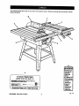
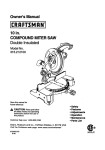
Owner's Manual
10 in. Stationary
TABLE SAW
Model No.
315.228310
Save this manual for
future reference
".I
•
•
•
•
•
•
_, CAUTION:
Read and follow all
Safety Rules and Operating
Instructions before first use of this
product.
Customer Help Line: 1-800-932-3188
Sears,
Roebuck
Visit the Craftsman
972000-524
10-98
and Co., Hoffman
Estates,
IL 60179
Safety
Features
Assembly
Operation
Maintenance
Parts List
USA
web page: www.sears.com/craftsman
NRTL/C
FULLONEYEARWARRANTY
ONCRAFTSMAN
TABLESAW
If thisrRRFTSMRN Table Saw fails due to a defect in material or workmanship within one year from the date of
purchase. Sears will repair it, free of charge,
Contact a Sears Service Center for repair.
If this productis used for commercial or rental purposes, this warranty applies only for 90 days from the date of
purchase.
This warranty gives you specificlegal dghts, and you may also have other rightswhich vary from state to state.
Sears, Roebuck and Co., Dept. 81"IWA, Hoffman Estates, IL 60179
Your saw has many features for making cutting operations more pleasant and enjoyable. Safety, performance
and dependability have been given top priority in the design of this saw making it easy to maintain and operate.
_,
CAUTION: Carefully read throughthis entire owner's manual before using your new saw. Pay close
attention to the Rules For Safe Operation and all Safety Alert Symbols, including Danger, Wam ng and
Caution. If you use your saw properlyand only for what it is intended, you will enjoy years of safe, reliable
service.
._
Look for this symbol to point out importantsafety precautions.It means attention!!!Your safety is involved.
WARNING:
The operation of any power tool can resultin foreign objects being thrown into your eyes,
which can result in severe eye damage. Before beginning power tool operation, always
wear safety goggles or safety glasses with side shields and a full face shield when needed.
We recommend a Wide Vision Safety Mask for use over eyeglasses or standard safety
glasses with side shields, available at Sears Retail Stores.
•
Warranty and Introduction..............................................................................................................................
2
•
Table Of Contents .......................................................................................................................................
2-3
•
Rules For Safe Operation ...........................................................................................................................
4-6
•
Electrical .........................................................................................................................................................
7
•
Glossary and Product Specifications.............................................................................................................
8
•
Unpacking and Accessories...........................................................................................................................
9
•
Loose Parts List......................................................................................................
•
Small Parts List .......................................................................................................................................
•
Tools Needed ...............................................................................................................................................
•
Labels ......................................................................................................................................................
14-15
•
Features ..................................................................................................................................................
16-17
•
Assembly .................................................................................................................................................
18-27
...................................... 10
11-12
13
InstallingHandwheels on Table Saw Base ..................................................................................................
18
Assembling Leg Stand ............................................................................................................................
18-19
CRAFTSMAN"
TABLESAW315.228310
2
Mounting
theLegStandontheTableSawBase........................................................................................
•
AssemblingTable Extensions......................................................................................................................
AligningTable Extensions ............................................................................................................................
19
20
20
Installingthe Rear Rail .................................................................................................................................
Installingthe Front Rail ................................................................................................................................
21
22
AligningRip Fence and Front Rail ...............................................................................................................
Mountingthe Motor ......................................................................................................................................
Installingthe Belt and Belt Guard ................................................................................................................
Checkingthe Throat Plate ............................................................................................................................
23
23
24
24
Installingthe Blade Guard ............................................................................................................................
Aligning the Riving Knife with the Blade ......................................................................................................
Checking Rip Fence and Blade Alignment ..................................................................................................
25
26
27
Adjustments.............................................................................................................................................
28-32
Replacing the Blade .....................................................................................................................................
28
Heeling (Paralleling) the Sawblade to Miter Gage Groove ........................................ t............................ 29-30
Setting the Bevel Stops and Indicator..................................................................................................... 30-31
Adjustingthe Miter Gage ..............................................................................................................................
31
Removing/ Replacing the Throat Plate ....................................................................................................... 32
•
Basic Operation/bf the Table Saw .......................................................................................................... 33-40
Causes of Kickback......................................................................................................................................
33
AvoidingKickback ........................................................................................................................................
33
Making Cutting Aids .....................................................................................................................................
Types of Cuts ...............................................................................................................................................
Making a Cross Cut ......................................................................................................................................
Making a Rip Cut ..........................................................................................................................................
Making a Miter Cut .......................................................................................................................................
Making a Bevel Cross Cut ............................................................................................................................
Making a
• Making a
Making a
Making a
33
34
35
35
36
36
Bevel Rip Cut ................................................................................................................................
Compound (Bevel) Miter Cut ........................................................................................................
Large Panel Cut ............................................................................................................................
Non-Through Cut ..........................................................................................................................
37
38
39
39
Making a Dado Cut ................................................. _.....................................................................................
40
•
Maintenance .................................................................................................................................................
41
•
Lubrication....................................................................................................................................................
41
•
Troubleshooting.......................................................................................................................................
42-44
•
Exploded View and Repair Parts List......................................................................................................
46-63
•
Parts Ordering / Service ...................................................................................................................
3
back page
CRRFTSMIIN"TABLESAW315.228310
The purpose of safety symbols is to attract your attention to possibledangers. The safety symbols, and the
explanations with them, deserve your careful attention and understanding.The safety warnings do not by
themselves eliminate any danger. The instructionsor warnings they give are not substitutesfor proper accident
prevention measures.
SYMBOL
A
MEANING
SAFETY ALERT SYMBOL
Indicates danger, warning, or caution,May be used in conjunctionwith other symbolsor
pictographs.
A
DANGER: Failureto obey a safety warningwill resultin serious injuryto yourself or to others.
Always follow the safety precautionsto reduce the risk of fire, electdcshock and personalinjury.
WARNING: Failure to obey a safety warningcan result in sedous injuryto yourselfor to others.
Always follow the safety precautionsto reduce the risk of fire, electdcshock and personal injury.
A
Note:
CAUTION: Failureto obey a safety warning may resultin propertydamage or personalinjuryto
yourselfor to others. Always followthe safety precautionsto reduce the risk of fire, electricshock
and personal injury.
Advisesyou of informationor instructionsvital to the operation or mainienance of the equipment.
IMPORTANT
Servicing requiresextreme care and knowledgeof the
system and shouldbe performed only by a qualified
service technician. For service we suggestyou return
the toolto your nearest Sears store or repair center.
Always use originalfactory replacement parts when
servicing.
_1= WARNING: Do not attempt to operate this tool
until you have read thoroughlyand understand
completely all instructions,safety rules, etc.
contained in this manual. Failure to comply can
resultin accidents involvingfire, electricalshock,
or serious personal injury.Save the owner's
manual and review frequently for continuingsafe
operation, and instructingothers who may use
this tool.
READ ALL INSTRUCTIONS
KNOW YOUR POWER TOOL. Read the owner's
manual carefully. Learn the saw's applications
and limitationsas well as the specificpotential
hazards related to this tool.
MAINTAIN TOOLS WITH CARE. Keep tools
sharp and clean for better and safer performance. Follow instructionsfor lubricatingand
changing accessories.
DO NOT USE IN DANGEROUS ENVIRONMENT. Do not use power tools near gasoline or
other flammable liquids,in damp or wet locations, or expose them to rain. Keep the work
area well lit.
USE THE RIGHT TOOL FOR THE JOB. Do not
force the tool or attachmentto do a job it was not
designed for. Use it only the way it was intended.
•
MAKE WORKSHOP CHILD-PROOF with
padlocks and master switches or by removing
starter keys.
•
KEEP CHILDREN AND VISITORS AWAY. All
visitorsshould wear safety glasses and be kept a
safe distance from work area. Do not let visitors
contact tool or extension cord while operating,
•
DRESS PROPERLY. Do not wear loose clothing,
gloves, neckties, rings, bracelets, or other
jewelry. They can get caught and draw you into
moving parts. Rubber gloves and nonslipfootwear are recommended. Also wear protective
hair coveringto contain long hair.
ALWAYS WEAR SAFETY GLASSES WITH
SIDE SHIELDS. Everyday eyeglasses have only
impact-resistantlenses; they are NOT safety
glasses,
KEEP THE WORK AREA CLEAN. Cluttered
work areas and work benches invite accidents,
DO NOT leave tools or pieces of wood on the
saw while it is in operation,
CRRFTSMRN"TABLESAW315.228310
NEVER STAND ON TOOL. Serious injurycould
occur if the tool is tipped or if the blade is unintentionally contacted.
4
BIULES FOR SAFE OPERATION
(Continued)
B
DO NOT OVERREACH. Keep proper footing and
balance at all times.
m
SECURE WORK. Use clamps or a vise to hold
work when practical. It's safer than using your
hand and frees both hands to operate tool.
M
USE THE PROPER EXTENSION CORD. Make
sure your extension cord is in good condition.
Use only a cord heavy enough to carry the
current your productwill draw. An undersized
cord will cause a drop in line voltage resulting in
loss of power and overheating. A wire gage size
(A.W.G.) of at least 14 is recommended for an
extension cord 25 feet or less in length. If in
doubt, use the next heavier gage. The smaller
the gage number, the heavier the cord.
M
AVOID ACCIDENTAL STARTING. Be sure
switch is oft when plugging in.
M
REMOVE WRENCHES AND ADJUSTING
KEYS. Get in the habit of checking - before
turning on tool - that hex I_eysand adjusting
wrenches are removed from tool.
M
CHECK DAMAGED PARTS. Before using the
tool again, check any damaged parts, including
guards, for proper operation and performance.
Check alignment of moving pads, bindingof
moving pads, breakage of pads, saw stability,
mountingand any other conditionsthat may
affect itsoperation. A damaged part must be
propedy repaired or replaced by a qualified
service technician at a Sears store or repair
center to avoid risk of personal injury.
M
M
DO NOT FORCE THE TOOL. It will do tbe job
better and more safely at the rate for which it
was designed.
M
NEVER LEAVE TOOL RUNNING UNATTENDED. TURN THE POWER OFF. Do not
leave tool untilit comes to a complete stop.
M
BEFORE MOUNTING, DISCONNECTING OR
REMOUNTING THE MOTOR; unplug the saw
and remove the switch key.
A
WARNING: When servicing, use only identical
Craftsman replacement pads. Use of any other
parts may create a hazard or cause product
damage.
M
NEVER USE THIS TOOL IN AN EXPLOSIVE
ATMOSPHERE. Normal sparkingof the motor
could ignite fumes.
M
MAKE SURE THE WORK AREA HAS AMPLE
LIGHTING to see the work and that no obstructions will interfere with safe operation BEFORE
performingany work using this tool.
M
DO NOT USE TOOL IF SWITCH DOES NOT
TURN IT ON AND OFF. Have defective switches
replaced by a qualified service technician at a
Sears store or repair center.
M
GUARD AGAINST ELECTRICAL SHOCK by
preventing bodycontact with grounded surfaces
such as pipes, radiators, ranges, refrigerator
enclosures.
M
GROUND ALL TOOLS. See Electrical page.
USE ONLY CORRECT BLADES. Use the right
blade size, style and cutting speed for the
material and the type of cut. Blade teeth should
point down toward the front of the table.
WEAR A DUST MASK to keep from inhalingfine
particles.
PROTECT YOUR HEARING. Wear hearing
protectiondudng extended periodsof operation.
USE RECOMMENDED ACCESSORIES, Using
improper accessoriesmay risk injury.
USE ONLY SEARS REPLACEMENT PARTS,
All repairs, whether electdcalor mechanical,
should be made by a qualified service technician
at a Sears store or repair center.
M
M
KEEP GUARDS IN PLACE and in good working
order. This includesthe blade guard, rivingknife,
and anti-kickback pawls.
M
DO NOT OPERATE THIS TOOL WHILE UNDER THE INFLUENCE OF DRUGS, ALCOHOL,
OR ANY MEDICATION.
M
STAY ALERT AND EXERCISE CONTROL,
Watch what you are doing and use common
sense, Do not operate tool when you ere tired.
Do not rush.
M
AVOID AWKWARD OPERATIONS AND HAND
POSITIONS where a sudden slip could cause
your hand to move into the blade. ALWAYS
make sure you have good balance,
M
ALWAYS SUPPORT LARGE WORK PIECES
while cuttingto minimize risk of blade pinching
and kickback. Saw may slip, walk or slide while
cutting large or heavy boards.
CHECK DIRECTION OF FEED. Feed work into
a blade or cutter against the direction of rotation
of the blade or cutter only,
DISCONNECT ALL TOOLS. When not in use,
before servicing,or when changing attachments,
blades, bits, cutters, etc., all tools shouldbe
disconnected from power supply.
5
CRAFTSMAN"TABLESAW315,228310
RULES FOR SAFE OPERATION
•
(Continued)
ALLOW THE MOTOR TO COME UP TO FULL
SPEED before starting e cut to avoid blade
binding or stalling.
GUARD AGAINST KICKBACK. Kickbackcan
occurwhen the blade sta$$s,
ddving the work
piece back toward the operator. It can pull your
hand intothe blade, resultingin sedous personal
injury. Stay out of the blade path and turn switch
off immediately if blade binds or stalls.
ALWAYS PUSH THE WORKP|ECE; never pull it
toward the saw.
DO NOT FEED THE MATERIAL TOO QUICKLY.
Do not fome the workpiece against the blade.
USE A SUPPORT FOR THE SIDES AND BACK
OF THE SAW TABLE when sawing wide or long
workpieces. Use a sturdy"outrigger" support if a
table extension is more than 24 inches long and
is attached to the saw, to preventtipping.
ALWAYS TURN OFF SAW before disconnecting
it, to avoid accidental starting when reconnecting
to power supply. NEVER leave the table saw
unattended while connected to a power source.
CUT ONLY WOOD, PLASTIC OR WOOD-LIKE
MATERIALS. Do not cut metal.
•
BEFORE CHANGING THE SETUP, REMOVING
COVERS, GUARDS, OR BLADE; unplugthe
saw and remove the switch key.
NEVER cut more than one piece at a time. DO
NOT STACK more than one workpiece on the
saw table at a time.
KEEP TOOL DRY, CLEAN, AND FREE FROM
OIL AND GREASE. Always use a clean cloth
when cleaning. Never use brake fluids, gasoline,
petroleum-based products,or any solvents to
clean tool.
DO NOT REMOVE THE SAW'S BLADE
GUARDS. Never operate the saw with any guard
or cover removed. Make sure all guards are
operating propedy befol'eeach use.
KEEP BLADES CLEAN, SHARP AND WITH
SUFFICIENT SET. Sharp blades minimize
stalling and kickback.
NEVER PERFORM ANY OPERATION FREEHAND. Always place the workpiece to be cut on
the saw table and position it firmly against the
fence as a backstop.
USE ONLY OUTDOOR EXTENSION CORDS.
Use only extension cords with the marking
=Acceptable for use with outdoorappliances;
store cords indoorswhile not in use." Use
extension cords with an electrical rating not less
than the saw's rating.Always disconnectthe
extension cord from the outlet before disconnectingthe productfrom the extension cord.
USE THE RIP FENCE. Always use a fence or
straight edge guide when ripping.
BEFORE MAKING A CUT, be sure all adjustments are secure.
•
BE SURE THE BLADE PATH IS FREE OF
NAILS. Inspect for and remove all nails from
lumber before cutting.
•
BE SURE THE BLADE CLEARS THE
WORKPIECE. Never start the saw with the blade
touching the workplace.
•
KEEP HANDS AWAY FROM CUTTING AREA.
Do not reach underneath work or in blade cutting
path with your hands and fingers for any reason.
Always turn the power off.
•
USE A PUSHBLOCK OR PUSH STICK for
workpieces so small that your fingers go under
the blade guam:d.
NEVER TOUCH BLADE or
other moving parts during use, for any reason.
_k
WARNING:
•
INSPECT TOOL CORDS AND EXTENSION
CORDS PERIODICALLY and, if damaged, have
repaired by a qualified sewice technicianat a
Sears store or repair center. Stay constantly
aware of cord locationand keep it well away
from the moving blade.
•
DO NOT ABUSE CORD, Never yank cord to
disconnectit from receptacle. Keep cord from
heat, oil, and sharp edges.
SAVE THESE INSTRUCTIONS. Refer to them
frequently and use to instructother users. If you
loan someone this tool, loan them these instructions also.
Blade coasts after being tumed off.
SAVE THESE INSTRUCTIONS
[RAFTSMRW TABLESAW316,228310
6
EXTENSION
CORDS
GROUNDING
Use only 3-wire extension cords that have 3-prong
groundingplugs and 3-pole receptaclesthat accept
the tool's plug. When using a power tool at a considerable distance from the power source, use an
extension cord heavy enough to carry the current that
the tool will draw. An undersized extension cord will
cause a drop in line voltage, resultingin a loss of
power and causing the motorto overheat. Use the
chart provided below to determine the minimumwire
size required in an extension cord. Only roundjacketed cords listed by Underwriter'sLaboratories(UL)
shouldbe used.
Length of Extension Cord
Up to 25 feet
26-100 feet
In the event of a malfunctionor breakdown, grounding
providesa path of least resistancefor electriccurrent
to reduce the risk of electric shock. This tool is
equipped with an electric cord having an equipmentgroundingconductorand a groundingplug. The plug
must be plugged into a matching outletthat is propedy
installedand grounded in accordance with all local
codes and ordinances.
Do not modifythe plug provided. If it will not fit the
outlet, have the proper outlet installedby a qualified
electrician. Improper connectionof the equipmentgroundingconductorcan result in a risk of electric
shook. The conductorwith insulationhaving an outer
surface that is green with or without yellowstripes is
the equipment-groundingconductor. If repair or
replacement of the electdc cord or plug is necessary,
do not connect the equipment-groundingconductorto
a live terminal.
Wire Size (A.W.G.)
14
12
When workingwith the tool outdoors,use an extension cord that is designed for outside use. This is
indicated by the letters WA on the cord's jacket.
Before using an extension cord, inspect it for loose or
exposed wires and cut or worn insulation.
_k
Check with a qualified electricianor service personnel
if the groundinginstructionsare not completely
understood,or if in doubt as to whether the tool is
properlygrounded.
CAUTION: Keep the cord away from the cutting
area and positionthe cord so that it will not be
caught on lumber, tools, or other objects dudng
cuttingoperations.
ELECTRICAL
INSTRUCTIONS
Repair or replace a damaged or worn cord immediately.
This tool is intendedfor use on a circuit that has an
outlet like the one shown in Figure 1. It also has a
groundingpin like the one shown.
CONNECTION
Your Sears Craftsman Table Saw is powered by a
precision builtelectric motor. It should be connected
to a power supply that Is 120 volts, 60 Hz, AC only
(normal household current). Do not operate this tool
on direct current (DC). A substantialvoltage drop will
cause a loss of power and the motor will overheat. If
the saw does not operate when plugged intoan
outlet, double check the power supply.
SPEED AND WIRING
The no-load speed of your table saw is approximately
3,600 rpm. This speed is not constantand decreases
under a load or with lowervoltage. For voltage, the
wiring in a shop is as importantas the motor's horsepower rating. A line intended only for lights cannot
properlycarry a power tool motor. Wire that is heavy
enough for a short distance will be too light for a
greater distance. A line that can supportone power
tool may not be able to supporttwo or three tools.
GROUNDING
PIN
COVEROFGROUNDED
0UTLETBOX
Fig. 1
7
rRRFTSNRN" TABLESAW31S.228310
Anti-Kickback Pawls
Toothed safety devices behind the blade designed to
stop a workpiece from being kicked back at the
operator during a rippingoperation.
Arbor
The shaft on which a blade or cutting tool is mounted.
Molding
A non-throughcut that gives a varied shape to the
workpiece and requires e special blade.
Push Stick
A device used to feed the workpiece throughthe saw
blade during narrowcutting operations. It helps keep
the operator'shands well away from the blade,
Bevel Cut
A cutting operation made with the blade at any angle
other than 90" to the saw table.
Rabbet
A notch in the edge of a workpiece.
Resaw
A cuttingoperation to reduce the thicknessof the
workpiece in order to make thinner pieces.
Compound Cut
A cut with both a miter angle and a bevel angle.
Crosscut
A cuttingoperation made across the grain or the width
of the workpiece.
Resin
A sticky,sap-based substance.
Dsdo
A non-throughcut that gives a square notch or trough;
requires a special blade.
RIp Cut
A cut made with the the grain of the workpiece.
Sswblade Path
The area directly in line with the blade -- over, under,
behind, orin front of it. Also, the workpiece area
which willbe or has been cut by the blade.
Featherboard
A device to help guide workpieces during ripcuts.
Freehand (for table saw)
Dangerous practice of making s cut without using dp
or miter fences. See Safety Rules.
Set
The distancethat the tip of the saw blade tooth is bent
(or set) outwardfrom the face of the blade.
Gum
A sticky, sap-based residue from wood products.
Throw-Back
Saw throwingback a workpiece;similar to kickback,
Heel
Alignment of the blade.
Through Sawing
Any cutting operationwhere the blade extends
completely throughthe workpiece.
Kerf
The material removed by the blade in a through cut or
the slot produced by the blade in a non-throughcut.
Trailing End
The workpiece end last cut by the blade in a dp cut.
Kickback
A hazard that can occur when blade binds or stalls,
throwingworkpiece back toward operator.
Workp|ece
The item on whichthe cutting operation is being done.
The surfacesof a workpiece are commonly referred to
as faces, ends, and edges.
Worktable
The surface on which the wodq_ece rests while
performinga cutting operation.
Leading End
The end of the workpiece pushed into the cutting tool
first.
Miter Cut
A cutting operation made with the miter gage at any
angle other than 0".
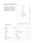
Blade Arbor
Blade Diameter
Blade Tilt
5/8 in.
Rating
10 in.
120 V, 60 Hz - AC only
Input
0" - 45"
13 Amperes
No Load Speed
3,600 RPM
Table Size without table extensions
20 in. x 27 in.
Cutting Capacity with Miter at 0"/Bevel 0":
3-3/8 in.
Table Size with table extensions
44 in. x 27 in.
Cutting Capacity with Miter at O'/Bevel 45":
2-1/4 in.
rRRFTSNlUI" TABLESAW$1G,228310
8
Your new table saw has been designed to give you
many years of high quality performance. To insure
this goal, proper care and treatment is important.
Careful treatment begins with removing all pads from
the cartonand checking them against the list of loose
parts.The long box contains the rails. The large box
holdsall other parts, which are detailed in the Loose
Parts List.
•
II Remove the wax paper covering on the table. Use
any ordinary household type grease and spot
remover. Immediately apply a coat of automotive
type paste wax to the table and table exensions.
,_
WARNING: To prevent accidental startingthat
could cause possibleserious personal injury,
assemble all parts to your saw before connecting
it to power supply.Saw should never be
connected to power supplywhen you are
assembling parts, making adjustments, installing
or removingblades, or when not in use.
,_
WARNING: If any parts are missing,do not
operate this tool untilthe missing parts are
replaced. Failure to do so could result in possible
serious personal injury.
Separate the saw and all parts from the packing
materials and check each against the packing list,
especially the small parts that can be hidden in the
packing material
Note: Do not discard the packing materials until you
have carefully inspected the saw, identified all
parts, and satisfactorily operated your new saw.
_IL WARNING: Never use gasoline, naptha, or
other highlyvolatile solvents. Do not ever let
brake fluids, gasoline, petroleum-based
products,or penetrating oilscontact plasticparts.
Such chemicals can weaken or destroy plastic.
The following recommended accessoriesare currentlyavailable at Sears Retail Stores.
•
Fence Guide System
•
7 in. Stack Steel Dado
•
Guide Master
•
7 in. x 9/16 in. Stack Dado
•
Box Joint & Miter Guide
•
7 in. MoldingHead Set
•
Universal Jig
•
Taper Jig
•
•
2 Bit MoldingHead Set
Saw Baskets
•
10 in. Sanding Disc
•
Jointer Clamps
•
•
8 in. Sanding Disc
Elite Dado
•
Specialty Throat Plate
•
Miter Gage Hold Down Clamp
•
ExcaliburDado
•
Align-A-RipXRC Rip Fence
•
7 in. Adj. Dado 36 tip
•
Dust CollectionSystem
•
7 in. Adj. Dado 24 tip
,_
WARNING:
The use of attachments or accessories not listed might be hazardous.
9
[RAFTSMAN" TABLESAW315.228310
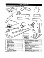
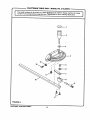
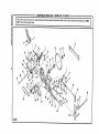
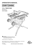
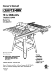
The following items are included with your Table Saw.
A
G
I
D
J
o
Q
Figure 2 a
A.
B.
C.
D.
E.
F.
G.
H.
I.
J.
K.
L.
M.
N.
Table Saw Base .................................................... 1
Belt ....................................................................... 1
Belt Guard (2 Piece) ............................................. 1
Blade Guard Assembly
(Hardware Shown Separately) ............................. 1
Wrench ................................................................. 1
Handwheel (Hardware Shown Separately) .......... 2
Leg Brace, lower (short) ....................................... 2
Leg Brace, lower(long) ........................................ 2
Leg Brace, upper (short)....................................... 2
Leg Brace, upper (long) ........................................ 2
Leg ........................................................................ 4
Miter Gage ............................................................ 1
Motor .................................................................... 1
Motor MountingPlate
(Hardware Shown Separately) ............................. 1
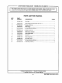
O.
P.
Q.
R.
S.
T.
U.
V.
W.
X.
Y.
Z.
tRRFTZMRI¢
TABLE SAW 315.228310
10
Rail, Front (Hardware Shown Separately)............ 1
Rail, Rear (Hardware Shown Separately) ............ 1
Rip Fence ............................................................. 1
Blade Guard Bracket ......................... ;.................. 1
SwitchAssembly ......,, ......................................... 1
Switch Key ............................................................ 1
Table Extension .................................................... 2
Hardware for MountingMotor, Motor Mounting
Plate, and Belt Guard (Shown Separately) ........... 1
Hardware for Table Extensions
(Shown Separately) .............................................. 1
Hardware for Leg Stand, LevelingFeet, and
MountingSaw Base
(Shown Separately) .............................................. 1
Hardware for Blade Guard Bracketand
Blade Guard Assembly (ShownSeparately) ........ 1
Owner's Manual (Not Shown)............................... 1
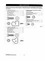
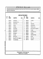
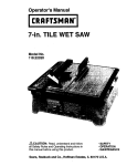
Checkallloosepartsfromtheboxwiththelistontheprevious
page,thefiguresbelowandonthefollowing
page,Smallitemssuchasfasteners
andendcapsareshowninfigures2 b and2 c. Followtheinstructions
in
theAssembly
sectiontoassemble
yournewsaw.
F.
Hardware for Handwheel ................................... 2
screw (3/16-24 x 1/2 in.)..................................... 2
Hardware for Leg Stand, LevelingFeet, and
MountingSaw Base
flat washer (3/15 in.) ........................................... 2
Hardware for Leg Stand ..................................... 1
Xo
carriage bolt (5/16-18 x 3/4 in.) ........................ 24
flat washer (5/16 in.)......................................... 24
hex nut (5/16-18) .............................................. 24
V. Hardware for MountingMotor, Motor Mounting
Plate, and Belt Guard
Hardware for Mounting Motor ............................ 1
hex bolt (5/16-18 x 1 in.) .................................... 4
Hardware for Leveling Feet ................................ 1
flat washer (5/16 in.) ........................................... 8
lock washer (5/16 in.) .......,.................................. 4
leveling foot ........................................................ 4
flat washer (5/16 in.) ........................................... 8
hex nut (5/16-18) ................................................ 4
hex nut (5/16-18) ................................................ 8
Hardware for Motor MountingPlate ................... 1
hex bolt (5/16-18 x 5/8 in.) ................................. 2
m
Hardware for MountingSaw Base ..................... 1
hex belt (5116-18 x 1/2 in.) ................................. 4
Hardware for Belt Guard .................................... 1
flat washer (5/16 in°)........................................... 8
hex nut (3/16-24) ................................................ 4
hex nut (5116-18) ................................................ 4
flat washer (3/16 in) ............................................ 4
Fig. 2 b
W. Hardware for Table Extensions.......................... 1
hex bolt (5/16-18 x 1-1/4 in.) .............................. 8
flat washer (5/16 in.) ......................................... 16
hex nut (5/16-18) ................................................ 8
11
[IIRFrSMRIr
TABLESAW31S.228310
Check all loose parts from the box with the list and figures below and on the previouspages, Small items such
as fasteners and end caps are shown in figure 2 c. Follow the instructionsin the Assembly sectionto assemble
your new saw.
Y. Hardware for Blade Guard Bracket and Blade
Guard Assembly
O. Hardware for Rail, Front ..................................... 1
square head bolt (5/16-18 x 1 in..) ..................... 6
flat washer (5/16 in.) ........................................... 6
Blade Guard Bracket .......................................... 1
hex nut (5/16-18) ................................................ 6
hex cap screw (5/16-18 x 1/2 in.) ....................... 2
end cap for front rail ........................................... 2
lock washer (5/16 in.) ......................................... 2
screw (5/32-32 x 1/2 in.) ..................................... 2
©
Blade Guard Assembly....................................... 1
socket head cap screw (1/4-20 x 3/8 in.) ........... 3
flat washer (1/4 in.) ..._......................................... 3
Fig. 2 c
F,
Hardware For Rail, Rear .................................... 1
square head bolt (5/16-18 x 1 in.) ...................... 6
flat washer (5/16 in.) ........................................... 6
hex nut (5/16-18) ................................................ 6
end cap for rear rail ............................................ 2
screw (5/32-32 x 1/2 in.) ..................................... 2
CRAFTSMAN"TABLESAW315.228310
12
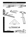
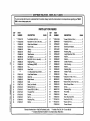
The followingtoolsare needed for assembly and alignment. Note: The five hex keys listedbelow have been
providedwith your saw. The remaining tools are typicalshop toolsand are not included with your saw.
SMALLI MEDIUM
PHILUPSSCREWDRIVER
NUTDRIVER
8 mm,10 mm,and12 mrn
HEXKEYS(PROVIDED)
and6 mm
COMBINA_ONSOUARE
HAMMER
45°TRIANGLE
WRENCHES:
8 mm,10 mm,and12 mm
ADJUSTABLE
WRENCH
FRAMINGSQUARE
13
rRRFTSMRN" TABLESAW315.228310
/
The followinglabels are found on your saw in the locationsshown. Read all warnings and this owner's manual
before using saw,
B
F
C
D
G
H
e
o
o
B
AWARNINI
• RaisedGuard
CanDropon
Spinning
Bladeand
Break.
•ToReduceThe
RiskofInjury,
GuardMust81
In Place
DuringUse.
,Alignand
Tighten
RivingKnife
Fasteners
BeforeUse.
A
10 inch Table Saw
36QOIh_M
120VOLTS
60HzACONLY
13A
WARNING:WHEN
SERVICING, USE ONLY IDENTICAL
CRAFTSMANREPLACEMENTPARTS.
MODEL 315.228310
MAD_ IN TAJWAN
SEARS, ROEBUCK AND CO.
S_R.NO.
i
_i
I
sr_l_4_
TOOL
• Customer Help Line 1-800-932-3188 ,
CRAFTSMAN"
TABLESAW315.228310
14
Fig, 4 a
I
When Mounting an Auxiliary Fence Face, Position
Hardware Beyond Arrow at Bight and Left as Indicated.
_ Mounting
WARNING
Keep Fasteners Away From Blade.
C
D
E
Do Not Lift Saw With Rails
ILor Extensions Tables.
]
Debris on rail can misalign
,A, WARNING
the rip fence. Workpiece
could bind or suddenly
kick back. You could be hit
or cut. Clean debris off
fence rail before
F
positioning
fence.
A WARNING
G
• Attach Blade Guard
,_LLON I
Assembly Before
Operating this Saw
• Read Owners
PUSHOFF
H
Turn Clockwise
Increase Blade
to
Angle.
®
A WARNING
Turn Clockwise
Blade.
to Raise
"rumCounterclockwise to
Lower Blade.
• For your safety, read owners manual before
operating saw.
• Wear eye p_otection.
• Keep blade guard down and In place for through
cuts.
• Keep hands out of path of saw blade.
• Do not perform any operation freehand.
• Know how to reduce the risk of kickback.
See instructions for ripping.
• Never reach around o¢ over/Niw blade.
15
• When ripping, use push stick when fence is set
2 Inches or lees from blade.
• When ripping, use push block and auxllary fence
when fence Is set between 1/2 and 2 inches from
blade. Oo nut make rip cuts narrower than 1/2 Inch.
•Tum off tool and walt for saw blade to stop before
moving workplece or changing settings.
• Disconnect the saw from the power source before
changing blade or se_icing.
• Do not expose to rbln or use in damp places.
Fig. 4 b
I:RRFTSMIIN"
TABLE
SAW315.228310
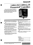
KNOW YOUR TABLE
SAW
ANTI-KICKBACK
PAWLS
BLADE
BLADE
REARRAIL
RIVINGKNIFE
ORSPREADER
RIPFENCE
ALIGN-A-CUT
INSERT
MITER
GAGEGROOVE
TABLE
EXTENSION
SCALE
EXTENSION
TABLE
FRONT
RAIL
GAGE
BEVEL
HANDWHEEL
SWITCH
WITH KEY
RIPFENCE
HANDLE
SCALE
HANDWHEEL
LEGSTAND
BELTCOVER
'LEVELINGFOOT
BEVEL
LOCKHANDLE
MOTOR
CRAFTSMAN"
TABLESAW315.228310
16
Fig. 5
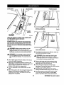
/ERVIEW
, ,,e upper portion of the blade projects up through the
table, surrounded by an insertcalled the throat plate.
The height of the blade is set with a handwheel and
locked with a handle, both on the front of the cabinet.
To accommodate wide panels, the tabletop has
extensions on each side. Detailed instructionsare
provided in the Operationsection of this manual for
the basic cuts: cross cuts, miter cuts, bevel cuts, and
compound cuts.
To tilt the blade for a bevel cut, use the bevel
handwheel on the side of the cabinet. A bevel scale
on the front of the cabinet shows the blade angle.
Inside the cabinet, adjustable positive stops control
the degree of tilt.
Use the miter gage with a bevel cross cut (compound
cut) and the rip fence with a bevel ripcut. Other cuts
require special attachments, which have detailed
instructions to reduce risk of injury and ensure the
best performance from your new saw.
For cuts with the blade straight up and cutting across
the grain (cross cuts or miter cuts), use the miter gage
to set the angle and pushthe wood into the blade. To
cut with the blade straight up, along the grain of the
wood (rip cuts), use the rip fence to guide the wood.
Push smaller pieces with a pushblockor pushstick.
Before attempting to use your saw, familiarize yourself
with all operating features and safety requirements of
your Sears Craftsman table saw. The saw's features
are described below.
ALIGN-A-CUT INSERT - A pt_,stic insert on which
marks may be made to indicate the locationof the
sawcut on the workpiece.
ANTI-KICKBACK PAWLS - KickbackIs a hazard in
which the workpiece is thrown back toward the
operator. The toothed pawls are designed to snag the
workpiece to prevent or reduce injury should kickback
indicator shows the exact angle for a miter cut, with
positive stops at 90" and 45".
MITER GAGE GROOVES - The miter gage ddes in
these grooves on either side of the blade.
MITER GAGE KNOB - Located on the miter gage,
this knob locks in the cutting angle after selection.
MOTOR (13 AMP) - The powerfulinductionmotor is
3HP, with capacitor start and V-belt drive, and is
housed in a sturdy steel base.
Occur.
BEVEL HANDWHEEL - This handwheel, on the right
side of the cabinet, tilts the blade for a bevel cut.
RAILS - Front and rear rails providesupportfor large
workpieces end the ripfence.
BEVEL SCALE - The easy-to-road scale on the front
of the work.standshows the exact blade angle.
RiP FENCE - A sturdy metal fence guides the
workpiece and is secured with the rip fence handle.
Grooves run along the top and sides of the ripfence
for usa with optional clamps and accessories.
RIP FENCE HANDLE - The handle on the front of the
rip fence releases the rip fence or locks it in place.
BLADE -This saw is providedwith a Craftsman 64
tooth, 10 in. steel blade. The blade is adjusted with
bevel and height handwheels on the cabinet. Bevel
angles are locked with a handle below the front rail.
WARNING: Be sure to use only blades rated for
at least 5,000 rpm and recommended for use on
this saw. Check with your nearest Sears retail
store.
RIVING KNIFE OR SPREADER - Located directly.
behindthe blade, it keeps cut edges from bindingand
supportsthe blade guard.
SCALE - Found on the front rail, the easy-to-road
scale providesprecise measurementsin dp cuts.
SWITCH WITH KEY - Your table saw has an easy
access power switch located below the front rail. The
yellow switch key must be removed from the hardware bag and inserted into the switchbefore saw can
be operated. To lock the switch in the OFF position,
remove the switch key from the switch. Place the key
in a location that is inaccessibleto childrenand others
not qualified to use the tool.
BLADE GUARD - Always keep the guard down over
the blade for through-sawingcuts.
BEVEL LOCK HANDLE - This handle, placed just
under the worktable surface on the front of the cabinet, locks the angle setting of the blade. Be sure the
handle is hanging straight down before tilting the
blade. If it is not straight down, it may jam and bend
the lockingbolt.
HEIGHT HANDWHEEL - Use this handwheel to lower
and raise the blade for adjustments or replacement. It
is locatedon the front of the cabinet.
TABLE EXTENSIONS - Removable stamped steel
extensions, 12 in. by 27 in., supportlarger
workpieces,
MITER GAGE - This gage aligns the wood for a
crosscutat an angle other than 90". The easy-to-road
17
CRAFTSHAN"TABLESAW315.228310
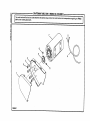
Assembly is best done in the area where the saw will be used. When you remove the table saw base, loose
parts, and hardware from the packing matedals, check all items with the loose parts listand drawing. If you are
unsure about the descriptionof any part, refer to the drawing. If any parts are missing, delay assemblinguntil
you have obtained the missingpart(s).
INSTALLING
BASE
HANDWHEELS
ON TABLE
SAW
Note: If you do not usa the leg stand and mount the
saw table base on a bench instead of the legs, go to
the procedurefor Assembling Table Extensions. Be
sure the 'bench surface has an opening for sawdust to
fall through.The opening shouldbe as large as the
opening in the bottomof the saw table base, A height
of 36 inchesfrom the top of the saw table to the floor
is recommended.
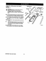
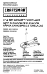
See Figure 6.
•
Each handwheel bag contains a handwheel, a
screw (3/16-24 x 1/2 in.), and a flat washer (3/16
in.).
•
Alignhandwheelsto the shaftends that extendfrom
the frontand rightside of the table saw base. Match
the fiat spotson the shaftand insidethe handwheeL
Inserta screwand a fiatwasher in the handwheel
ASSEMBLING LEG STAND
See Figures 7 and 8.
center and tightenwitha 4 mm hex key.
•
HANDWHEEL
TABLE
SAWBASE
SHAFTEND
Take from the leg stand hardware bag the following:
24 carriage bolts (5/16,18 x 3/4 in.)
32 flat washers (5/16 in.)
32 hex nuts (5/16-18)
4 levelingfeet
Note: Remaining hardware from this bag is used for
mountingleg stand on the table saw base.
•
Take 4 legs and 8 braces from loose parts.
•
Place a shortupper brace insidetwo of the legs,
with the legs wide end up. (Upper braces have two
large holes in each end.) Make sure the two
dimples on the leg align with the two small holes on
each brace.
UPPERBRACE
WASHER
SCREW
WASHER
HEXNUT
%
Fig. 6
CARRIAGE
LOWERBRACE
LEG
HEXNUT
LEVELING
FOOT_
[RRFTSMIIN" TABLESAW315,228310
18
Fig. 7
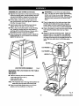
ASSEMBLING
LEGSTAND(Continued)
_k
• Align the two large holes on the brace and the legs.
Insert the cardage bolts. Add flat washers and hex
nuts and hand tighten. Repeat for the other short
upper brace. These are the front and back sets.
• For the sides, install a long upper brace on two
legs. Add hardware and finger tighten. Repeat for
the other long upper brace.
•
Place the leg stand on the table saw base. Align
the holes in the table with the holes in the end
braces. Make sure the Craftsman label faces the
front of the saw (same side as height handwheel).
•
Place a flat washer on each bolt and insertthrough
hole. Add a flat washer and a hex nut. Hand
tighten.
•
Repeat for the three remainingholes. Tighten all
hardware with a 12 mm wrench. You may find it
helpfulto use two wrenches, one wrench to hold
the head of the boltand one to tightenthe hex nut.
Leave the saw upside downto add table extensions.
• Use the same steps to installthe lower braces.
Tighten all hex nutswith a 12 mm wrench.
• Place a hex nut and flat washer on each leveling
foot. install the levelingfeet from the bottomof
each leg with the boltspointingup. Secure with a
fiat washer and hex nut but do not tighten.
• Move the leg stand to desired location. Adjustthe
leveling feet with a 12 mm wrench, then securely
tighten the top hex nut.
WARNING: Do not lift the saw table without
help. The table saw base weighs approximately
95 Ibs. Hold it close to your body. Keep your
knees bent and liftwith your legs, not your back.
Ignoringthese precautionscan result in back
injury.
HEXI,
LEGSTANDSHOWNASSEMBLED
LEGSTAND
Fig. 8
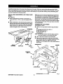
MOUNTING THE LEG STAND ON THE TABLE
SAW BASE
See Figure 9.
• Take the followingfrom the hardware bag:
4 hex bolts(5/16-18 x 1/2 in.)
4 hex nuts (5/18-18)
8 flat washers (5/16 in.)
Note: This hardware was in the bag with hardware for
assemblingthe leg stand and levelingfeet.
• Place the saw table upside down on a smooth
surface, such as cardboard, on the floor.
Fig. 9
19
CRAFTSMRN"TABLESAW315.228310
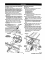
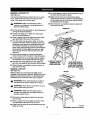
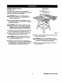
ASSEMBLING
•
TABLE EXTENSIONS
See Figure 10.
• Locate the table extensions and the smal_hardware
bag with the following:
_i,
8 hex bolts(5/16-18 x 1-1/4 in.)
8 hex nuts (5/16-18)
16 fiat washers (5/16 in.)
,_
WARNING: The table extensions not only
providea supportfor large or wide pieces of
material, but help protect you. Serious injury
can result from workpiece bindingor kickback
due to twisted rails or a misaligned rip fence.
•
With the saw upside down, align table extensionsto
the saw table. Put a flat washer on each bolt, and
attach the extensionsto the table by insertingbolts
through holes from the direction of the table.
•
Slip the remaining flat w_shers and hex nuts on the
bolts. Lightly tighten with a 12 mm wrench.
Get help to stand saw assembly updght usingthe
center saw table. Do not grasp saw by extensions.
WARNING: Do not lift the saw table without
help. Hold it close to your body. Keep your
knees bent and lift with your legs, not your back.
Ignoringthese precautionscan result in back
injury.
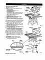
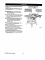
ALIGNING TABLE EXTENSIONS
See Figure 11.
A good alignment allowsthe railsto slide on easily.
•
Stand at the frontof the saw and line up the front
edges of the table and extensions.
• if adjustmentsare needed, put a blockof wood
where the extension meets the table, and tap the
blockof wood with a hammer. Check and repeat
untilthe frontedges are even.
•
Lift each extension slightlyuntilit is higherthan
table (if necessary, place a blockbelow and tap
upward). Center the blockof wood over the edges
and tap it. Recheck the front alignment. If even,
tighten the screwswith a 12 mm wrer,_h.
BLOCK
OFWOOD
TABLE
EXTENSION
TABLE
EXTENSION
SAW
TABLE
BLOCK
OFWOOD
TAP
HERE
TABLE
EXTENSION
Fig. 11
HEX
HEAD BOLT
FLA;
WASHER
HE](NUT
Fig. 10
eRRFTSMRI_ TABLESAW3152.28310
20
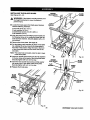
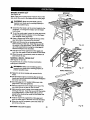
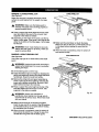
INSTALLING
THE REAR RAIL
SQUARE
HEADBOLTS
See Figures 12 - 14.
,_
•
WARNING: Front and rear rails must be
installedand carefully aligned to reduce the risk
of kickback. Kickbackcan result in serious injury.
NUT
FLAT
WASHER
From the carton, remove the rear rail and the
followinghardware:
TABLE
6 square head bolts(5/16-18 x 1 in.)
6 flat washers (5/16 in.)
6 hex nuts (5/16-18)
Right and left end caps for rear rail
2 screws (5/32-32 x 1/2 in.)
Note: Remaininghardware from this hardware bag is
used for installingthe front rail and end caps.
REARRAIL
• At the back of the table, put the square head bolts
in the holes in the edge of the table and extensions
so the bolt heads extend outward 1/2 in.
•
Under the table, looselyattach washers and hex
nuts onto bolts. Slide the slot on the rear rail over
the bolts. Adjust each boltto fit the rail closelyto
the table.
•
Positionrail so that right hand edge extends 2-1/2
inches beyondtable extension.
•
Push the rail against table and tighten each nut with
a 12 mm wrench.
•
If the railjams and does not slide easily over the
bolts, re-alignthe table extensions.
•
Put the end caps on the rail ends. Insert the screws
and tighten with a phillipshead screwdriver.
SLOT
REARRAIL
Fig. 13
TABLE
EXTENSION
ENDCAP
SQUARE
HEADBOLTS
HEXNUT
FLAT
WASHER
SCREW
Fig. 12
REAR OF SAW
21
Fig. 14
CRRFTSNAN" TABLE SAW 315.228310
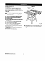
INSTALLING
THE FRONT RAIL
SOUARE
HEADBOLTS
See Figures 15 and 16.
•
Get the front rail the switch assembly, and the
followinghardware:
6 square head botts (5/16-18 x 1 in.)
6 fiat washers (5/16 in.)
6 hex nuts (5/16-18)
2 screws (1/4-20 x 3/8 in.) (located on switch plate)
2 square nuts (1/4-20) (located on switch plate)
Right and left end caps for front rail
2 screws (5/32-32 x 1/2 in.)
HEX NUT
TABLE
EXTENSION
FLAT
WASHER
• Set aside end caps and screws untilyou have
alignedthe dp fence and front rail.
•
Insertthe six square head boltsinto the table and
extensions,so the bolt heads extend outward 112
in.
•
Loosely attach a washer and a hex nut to each bolt.
•
The back of the rail has two slots.Slide the upper
slot over the bolts. (Bottom slot is for switch.)
• Alignthe rail left to fight - Match the 7-1/8 in. mark
on the dghtscale to the dghtedge of the table saw
base (main table). See Figure 16.
Fig.!5
• Snug the rail against table. Finger-tighteneach nut
on the table and extensions.
•
FRONTRAIL
ENDCAP
Locate the switchassembly. The two screws are
installedthrough the back of the switchplate with
the square nuts extendingout toward the front.
Note: The square nuts are loose on the switch plate.
•
Slide the square nuts intothe lower slot of the rail.
•
Slide the switch assembly to a convenient position,
leaving ample clearance for the haedwheeL Tighten
securelywith a screwdriver. Do not tighten the rail
bolts.
SCALE
SCREW
A_ WARNING: Place the switch out of the
immediate work area to avoid accidentally
turning it off dudng operation.
TABLE
TABLE
EXTENSION
TABLE
EXTENSION
_IRIn.MARK
R_HTBCALE
SWITCH.
WITHKEY
ALIGNINGTHERIPFENCEANDFRONTRAIL
MOUNTING
See Figures 17and 18.
See Figure 19.
The ripfence scale indicatoris installedon the right
side of the rip fence but can be removed and reinstalled on the left side if needed. If a cutting operation
requiresplacing the rip fence on the left side of the
blade, and you find relocatingthe scale indicator
necessary, simply unscrewand re-attach it.
•
•
Slide the rip fence back and forth. It should move
freely with about 1/16 in. clearance between the rip
fence and table surface. If it doesn't, loosen the
nuts holdingthe front rail and adjust it up or down.
•
Remove the rip fence and repeat on other side of
the blade. When the fence rides smoothly,
tighten all rail hex nuts with a 12 mm wrench.
•
Attach the end caps and s_rews with a phillips
screwdriver.
Note: Remaining hardware from this bag is used for
installingthe belt guard.
•
Release the bevel lock handle (frontof cabinet)
and turn the bevel handwheel (side of cabinet) until
the blade is fullyvertical. Retightenthe bevel lock
handle.
• Align the holes in the motormountingplate and the
motor bracket so the top edges are even. Place a
flat washer on the 1 in. boltsand insert into the
holes.
•
NCE
•
•
oo
REARRAIL
Locate the motorassembly, the motor mounting
plate and the followinghardware:
4 hex bolts (5/16-18 x 1 in.)
8 flat washers (5/16 in,)
4 lock washers (5/16 in.)
4 hex nuts (5/16-18)
2 hex bolts(5/16-18 x 5/8 in.)
Hook the back of the rip fence over the rear rail.
Lower the frontof the rip fence into the groove on
the front rail.
•
THE MOTOR
Install a flat washer, lock washer, and a hex nut on
each belt. Hand tighten only. This is the motor
supportassembly.
Center the motorside to side on the motor mounting plate. Tighten the nuts with a 12 mm wrench.
Insert the two rodson the motor supportassembly
into holes in the cradle. Push the motor in as far as
it will go. Thread the two hex bolts intothe cradle
to clamp down on the rods. Do not securely
tighten bolts yet.
HEX BOLTS
Fig. 17
TOINSTALL
SCALEINDICATOR
ONLEFT
RODS
RIPFENCE
MOTOR
BRACKET
FRONTRAIL
MOTOR
ASSEMBLY
WASHER
1 In.HEXBOLTS
Fig. 18
23
Fig. 19
CRRFTSNRN"
TABLE
SAW315.228310
INSTALLINGTHEBELTANDBELTGUARD
See Figures20 and 21.
•
Get the belt, belt guard, 4 flat washers (3/16 in.)
and 4 small hex nuts (3/16-24).
•
Lower the blade by turningthe height handwheel.
•
Slip the belt on the saw pulley (inside cabinet). Lift
the motorforward and place the belt on the motor
pulley.
BELT
•
Check that the belt is straightand both pulleysare
aSgned. If not, adjustthe motoron the motor
supportassembly. Refer to Mountingthe Motor.
• Raise the saw blade all the way up.
•
Pullthe motor out until the belt is taut. Securely
tighten the hex boltsabove the rods with a 12 mm
wrench.
•
Put your hand around the belt halfway between the
two pulleysand squeeze the be_tuntil bothsides of
the belt touch. The motor shouldmove freely as
you squeeze the belt. If i_does not, loosen the hex
boltsand readjust the belt tension.
•
Lower the blade with the height handwheel. Lift the
motorforward and remove the belt.
•
Open the hinged belt guard and place it over the
motorscrews on the motorpulley. Secure with fiat
washers and hex nuts. Securely tightenthe hex
nuts with a 10 mm wrench.
•
Replace the belt and snap the guard closed.
•
Check the clearances by indexingthe blade. Turn
the bevel hendwheel to 45" and back. Use the
height handwheelto fully lower and raise the blade.
BELTI
Fig. 21
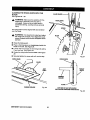
CHECKING THE THROAT PLATE
See Figure 22.
j_
•
SAWPULLEY
MOTORSUPPORT
ASSEMBLY
CAUTION: The throatplate must be even with
the table surface. If it is too high or too low, the
workpiece can catch on uneven edges and
cause kickback.
Make sure the throat plate is flush with the table
top. To change height of the throat plate, loosen the
flat head screw that secures the throat plate and
adjust the four setscrewswith a 2 mm hex key. Do
not allow the throatplate to bow up above the table
surface.
2 mm
HEXKEY
SETSCREW
FRAMINGSQUARE
IROATPLATE
TABLETOP
MOTOR
MOTORSCREWS
rRRFTSMRN"TABLESAW315,228310
HEIGHT
HANDWHEEL
Fig. 20
24
BEVEL
HANDWHEEL
Fig. 22
INSTALLING
THE BLADE GUARD
SOCKET
HEADSCREWS
See Figures 23 - 25.
BLADE
WARNING: If the blade is not fully lowered, tum
the height handwheel to lower the blade to
prevent injury.
•
Locate the blade guard, the blade guard bracket,
and the followinghardware:
2
2
3
3
FLM
WASHER
hex bolts (5/16-18 x 1/2 in.)
lockwashers (5/16 in.)
socket head screws (1/4-20 x 3/8 in.)
fiat washers (1/4 in.)
• Align the lower end of the blade guard bracket and
the threaded holes of the cradle and insertthe hex
boltsand _ockwashers. Securely tk3htanwith a 12
mm wrench.
•
Remove the throat plate. See page 32.
•
Put the blade guard assembly in place on the table
top, aligningthe screw holes in the rivingknife to
the holes in the bracket. Align the hole in the front
of the rivingknife base with the screw hole in the
saw table.
Note: The screw hole is located under the slot in back
of the throat plate.
• Inserttwo socket head screws and two flat washers
in the two holes at the beck of the dying knife base.
Securelytighten with a 5 mm hex key.
• Insertthe third socket head screw and flat washer
into screw hole in saw table under throat plate.
Securelytighten with a 5 mm hex key.
• Replace the throat plate.
Fig. 24
SOCKET
HEADSCREW
BLADE
FLAT
RIVING
KNIFE
BLADE
GUARD
BRACKET
_NTI-KICKBACK
PAWLS
LOCK
WASHER
Fig. 25
HEX
Fig. 23
25
CRRFTSNnN"
TABLESAW315.228310
ALIGNINGTHERIVINGKNIFEWITHTHE
BLADE
BLADE GUARD
See Figures26 - 28.
_l,
RIVINGKNIFE
WARNING: Make sure the switch is off, the
switch key is removed, and your saw is
unplugged. Failure to do so could result in
accidental starting, causing serious personal
injury.
The rivingknife must be aligned with end centered
over the blade.
_I,
•
Raise the blade guard.
•
Place a framing square or straightedge beside the
blade on the left. See Figure 26.
Loosen the front screw on the riving knife with a
5 mm hex key. See Figure 27.
•
BLADE
WARNING: It is importantto install and adjust
the riving knife correctly. Poor alignment could
cause kLckbackand throw the workpiece at the
operator.
/
• Center the rivingknife over the blade. See Figure
28.
•
Fig. 27
Securelytighten the screw with a 5 mm hex key.
RIVINGKNIFE
RMNG KNIFE
BLADE
I
SAW
TABLE
/
/
_ROAT
PLA_
FRAMING
SQUARE
BLADE
FRAMINGSQUARE
Fig. 26
TOPVIEWOFSAWWITHRIVING
KNIFESHOWNCENTEREDOVERBLADE
Fig. 28
rRIIfTSMRN" TABLESAY/315.22S310
26
CHECKING RIP FENCE AND BLADE
ALIGNMENT
MITERGAGE
GROOVE
See Figures 29 - 31.
BLADE
RIPFENCE
FRAMING
SOUARE
The rip fence is self-aligning but shouldbe checked
before first use.
_,
WARNING: Failure to align the rip fence to the
blade can cause jams and kickback,resulting in
serious personal injury.
•
Slide the ripfence to the miter gage groove, which
is parallelto blade. Do not lock the rip fence.
•
Place a framing square against the blade, with the
long end under the ripfence. Note the distance.
•
Move the square to the back and measure the
length from the other end of the fence.
•
If the distancesare different, loosen the four screws
around the ripfence handle with a 6 mm hex key.
Alternate the order (loosen the screw opposite, not
next to the first one).
•
Hold the fence handle against the front rail and
align the rip fence with the blade.
•
Retightenthe screws in alternating order and check
the alignment.
•
Repeat untilthe rip fence is aligned.
Fig. 30
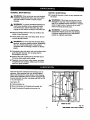
RIP FENCE
To complete assembly of the saw, plug the motorcord
into the back of the switch. Run the cord around the
side of the cabinet. Secure it to the side of the cabinet
with the cord clip and screw provided. Use care with
the cord around sharp edges. Your saw is now set up
to provide years of high quality performance.
RIPFENCE
MITERGAGE
GROOVE
BLADE
RIPFENCEHANDLE
FRAMING
SQUARE
€
Fig. 31
Note: To insure properself alignmentwhen positiOning rip fence, push sides of scale indicator
housingagainst front railbefore lookingrip
fence handle.
Fig. 29
27
CRaFTSMRN"TABLESAW315.228310
To avoid unnecessary setups and adjustments,a
good practice is to check your setups carefully with a
framing square and make practicecuts in scrap wood
before making finish cuts in good workpieces. Do not
start any adjustments until you have checked w_tha
square and made test cuts to be sure adjustmentsare
needed.
BLADE
GUARD
REPLACING THE BLADE
See Figures 32 - 34.
T0
LOOSEN
BLADE
_1, WARNING: Make sure the switchis off, the
switch key is removed, and your saw is
unplugged. Failure to do so could result in
accidental starting, resulting in serious personal
injury.
•
BLADE
Raise the blade guard and remove the throat plate.
TO remove, loosen the screw at the front with a
phillipsscrewddver and I!ftthe front end. Pull it out
toward the front end.
BLADE
WASHER
•
Raise the blade to its highest positionby turning
the height handwheel clockwise. Angle the blade
straight up by looseningthe bevel lock handle and
turning the bevel handwheet.Wedge a piece of
scrap wood against the frontof the blade. See
Figure 32.
• Loosen the blade nut with the bible wrench
provided with your saw. Remove the blade nut and
blade washer. Carefully remove the scrap wood
and blade.
SCRAP WOOD
BLADE
• To replace the blade with an accessory blade,
follow the instructionsprovided with the accessory.
I
• To install a standard blade, place the new blade on
the arbor shaft, with teeth pointing down towardthe
front of the saw, Wedge a piece of scrap woodat
the back of the blade. See Figure 34.
I
/
BLADEHUT
CAUTION: The teeth must point down toward
the front of the saw to work properly.Otherwise,
damage to the blade, saw, or workpiece can
occur.
•
Place the blade washer and the blade nut over
the blade arbor. Be sure the dome side of the
blade washer faces out from the blade and that
all items are snug againstthe arbor housing.
Tightensecurely.
•
Remove the scrap wood and rotate the blade by
hand to make sure it turns freely.
•
Slip the throat plate intothe opening and push it
toward the back of the saw to engage the spring
clip, Securely tighten the screw. If the throat plate
is not flush with the table, adjust the setscrews
with a 2 mrn hex key. [3o not allow the throat
plate to bow up above the table surface.
[RRFTSMRW TABLESAW$15.2283t0
/
ARBORSHAFT
28
Fig. 33
SCRAPWOOD
BLADE
BLADEGUARD
FRAMINGSQUARE
/
NUT
MITERGAGEGROOVE
Fig. 35
WASHER
TOTIGHTEN
BLADENUT
Fig. 34
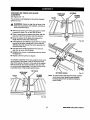
HEELING (PARALLELING) THE SAWBLADE
TO THE MITER GAGE GROOVE
See Figures 35 - 37.
(_
DO NOT loosen any screws for this adjustment
until you have checked with a square and made
test cuts to be sure adjustments are necessary.
Once the screws are loosened, these Items must
be reset.
_k
_l,
f
WARNING: Make sure the switch is off, the
switch key is removed, and your saw is unplugged. Failure to do so could result in accidental starting, resultingin serious personal injury.
MITERGAGEGROOVE
•
WARNING: The sawblade must be parallel to
the miter gage groove so the wood does not
bind, resulting in kickback.You could be hit or
cut.
j_
• Lift the blade guard. Raise the blade all the way by
turning the height handwheel.
• Mark one of the sawblade teeth at the front of the
blade. Place a framing square beside the blade and
just touching the marked tooth. Measure the
distance to the right miter gage groove.
• Turn the sawblade so the marked tooth is at the
back.
•
FRAMING
SQUARE
•
Fig. 36
If the distancesmeasured are different,adjust the
mechanismunderneath the saw.
WARNING: When reaching under the saw
table, wear gloves or first remove the blade.
Accidentalcontact with the blade could cause a
cut resultingin serious personal injury.
Remove the throat plate by loosening the front
screw with a phillips screwdriver.Lift the throat
plate and pull it out by the front end.
•
Lowerthe blade completelywith the height
handwheel. You can then access the table brackets
through the throat plate opening.
• From the back, loosen the three rear screws
holdingrear table bracket using a 12 mm wrench.
Move the square to the rear and again measure the
distanceto the right miter gage groove. If the
distancesare the same, the blade and the miter
gage groove are parallel.
•
29
If the toothwas too far from the square's blade,
move the rear bracket toward the miter gage
groove.Tap with a block of wood and hammer.
CRRFTSNRN"TABLESAW315.228310
•
If the tooth was too close to the square, back the
bracket away with the block of wood and hammer.
SETTING THE BEVEL STOPS AND INDICATOR
•
Tighten the screws, raise the blade and recheck.
,_
•
Repeat untilblade is parallel to miter gage groove.
•
If the blade Is not parattel,adjust the front table
bracket.Tilt the blade to 45" with the blade lock
handle and bevel handwheel.
•
From the back of the saw, toosenthe bolts holding
the front table bracket, as well as the rear table
bracket.
•
Repositionthe blade to 90" with the bevel handwheel and blade lock handle.
•
Lower the blade and move the brackets as needed.
Retightenall bracket screws.
Raise the blade and recheck. Repeat until the
blade is parallelto the miter gage groove.
•
•
See Figures 38 and 39.
WARNING: Make sure the switch is off, the
switch key is removed, and your saw is
unplugged. Failure to do so could result in
accidental starting, resultingin serious personal
injury.
The bevel scale shouldshow 0" when the blade is set
verticalat 90" to table, and 45" when blade is at 45" tilt.
•
•
•
Place the throat plate in the opening and push it
towardthe rear of saw base to engage the spring
clip.
Tightenthe screw. Do not allow the throat plate to
bow up above the table surface.
•
If the scale indicatordoes not point to 0", loosenthe
scale indicatorwith a screwdriver,adjustit within
the s_ot,and retightenthe screw.
•
If the blade angle is wrong, adjustthe 90" stop
screw (left of the blade, lookingfrom the front). Start
by turning the 90" stop screw three or four turns
with a 4 mm hex key.
SAWTABLEVIEWFROMBELOW
REAR
SAWTABLE
TABLEBRACKET
Check the blade angle with a combinationsquare.
Don't let the square touch a bladetooth. The blade
shouldbe at 90" and th_ scale indicatorat 0".
Note: The scale indicator isthe plasticplate on the
scale at the front of the cabinet.
Note: The keyslotin the throat plate willdrop over the
frontscrew.
•
Raise the blade all the way up by turningthe height
handwheel. Liftthe blade guard.
Loosen bevel lookhandle and turn the bevel
handwheel clockwiseto tilt the blade, Reverse it
and turn the handwheel counterclockwiseuntil it
stops.
/
90_STOPSCREW
45_STOPSCREW
4 mm
HEXKEY
REAR
BRACKET
SCREW(S)
FRONT
TABLEBRACKET
FRON
BRACKET
SCREW(S)
Fig. 38
Fig. 37
•
Turn the bevel handwhee] clockwiseonce, then
back counterclockwiseto square blade with table.
• Tighten the 90" stop screw and recheck that the
blade is square in a 90" position,If not, repeat,
When the blade is square, check the scale indicator. If it is not at zero, resetthe scale indicator as
before.
CRAFTSMAN*TABLESAW315.228310
30
• Check the 45" setting. Tilt the blade with the bevel
handwheel as far as it will go to the left. Place the
square against the blade (be sure the square is not
against one of the saw teeth). Ifthe blade is not at
45", unscrewthe 45" stop screw (right of blade),
turnthe handwheel untilthe blade is correct, and
tighten the screw. Recheck and repeat if necessary.
• Check that the scale indicatoris at 45°.
•
If not, loosen the scale indicatorwith a screwdriver,
adjust it withinthe slot,and retightenthe screw.
•
Loosen knob and pull out on stop pin to rotate miter
gage base past stop screws.
•
Loosen the lock nut of the 0" stop screw at the stop
pin with a 8 mm wrench.
•
Place a 90" square against the miter gage rod and
the miter gage base.
•
If the rod is not square, loosen the knob, adjust the
rod, and tighten the knob.
•
Adjustthe 0" stop screw until it rests against the
stop pin.
•
Adjustthe plus and minus45" stop screws using a
45" tdangle and the steps above.
MITER
GAGEROD
SCALE
INDICATOR
KNOB
MITER
GAGEBASE
Fig. 39
STOPSCREW
ADJUSTING THE MITER GAGE
See Figure 40.
You can set the miter gage at O"and plus or minus45"
with the miter gage stop pin and adjustable stop
screws
0° ADJUSTABLE
STOPSCREW
LOCKNUT
STOPPIN
Fig. 40
Note: The miter gage providesclose accuracy in
angled cuts. For very cloSe tolerances, test
cuts are recommended.
31
rRRFTSMRN" TABLESAW315.228310
REMOVING / REPLACING
PLATE
See Figure 41.
THE THROAT
THROATPLATE
KEYSLOT
,_
WARNING: Make sure the switch is off, the
switch key is removed, and your saw is
unplugged. Failureto do so could result in
accidental starting, resultingin sadous personal
injury.
SPRINGCLIP
TABLE
• To remove the throat plate, first loosen the screw in
the throat plate with a phillipsscrewdriverand lift
the front end. Pull it out toward the frontof the saw.
• To re-installthe throat plate, place It in the opening.
Push it towardthe rear of saw base to engage the
spdng clip.
Note: The keyslot in the throat plate willdrop over the
screw.
•
•
Check that the throat plate is even with the table
top. If not, adjust the four set screwswith a 2
mm hex key. See the procedure in the Assamb/y section.
Fig. 41
Socure_ytighten throat plate screw. Do not allow
the throat plate to bow up above the table surface.
CRIIFI3MAN" TABLESAW31tL_8310
32
BASIC OPERATION
OF THE TABLE SAW
A table saw can be used for straight-linecutting
operations such as cross cutting, ripping,mitering,
beveling, and compound cutting. It can make dado or
moldingcuts with optional accessories.
The three-prong plug must be plugged into a matching outletthat is propeity installed and grounded
according to all local codes and ordinances. Improper
connectionof the equipment can result in electdc
shock. Check with an electrician or service personnel
if you are unsure about proper grounding, Do not
modifythe plug; if it will not fit the outlet, have the
correctoutlet installed by a qualified electrician. Refer
to the Electrical page of this manual.
Note: This table sew is designed to cut wood and
wood compositionproductsonly.
To avoid pinchingthe blade, supped the work
properly before beginning a cut.
•
When making a cut, use steady, even pressure.
Never force cuts.
•
Do not cut wet or warped lumber.
•
Always hold your workpiecefirmlywith both hands
or with pushsticks.Keep yourbody in a balanced
positionto be ready to resist kickbackshouldit
occur. Never stand directlyin line with the blade.
•
Use the dghttype of blade for the cut being made.
CUTTING AIDS
See Figure 42.
Pushsticksare devices used for safely pushinga
workpiece through the blade insteadof using your
hands. They can be made in various sizes and
shapes from scrap wood to use in a specificproject.
The stick must be narrewet than the workpiece, with a
90" notch in one end and shapingfor a grip on the
other end.
CAUSES OF KICKBACK
Kickbackcan occurwhen the blade stalls or binds,
kickingthe workpiece back toward you with great
force end speed, if your hands are near the sewblade,
they may be jerked loose from the workpiece and may
contactthe blade. Obviously, kickbackcan cause
serious injury, and it is well worth using precautionsto
avoidthe risks.
A pushblock has a handle fastened by recessed
screws from the underside, Use it on non-through
cuts.
_IL
Kickbackcan be caused by any action that pinches
the blade in the wood, such as the following:
•
•
CAUTION: Be sure the screw is recessed to
avoid damaging the saw or workpiece.
PUSHBLOCKS
Making a cut with incorrectblade depth
• Sawing intoknots or nails in the workpiece
• Twistingthe wood while making a cut
•
Failingto supportwork
•
Forcinga cut
•
Cuttingwarped or wet lumber
•
Using the wrong blade for the type of cut
•
Not following correct operating procedures
•
Misusingthe saw
•
Fai{ingto use the ant'vkickback pawls
•
Cutting with a dull, gummed-up, or improperlyset
blade
AVOIDING
PUSHSTICKS
KICKBACK
• Always use the correct blade depth setting. The
top of the blade teeth should clear the workpiece
by 1/8 in. to 1/4 in.
• Inspectthe work for knotsor nails before beginning
a cut. Knockout any loose knots with a hammer.
Never saw into a loose knot or nail.
•
Fig.42
A featherboard is used when it is not practical to use
the miter gage, usually due to the size of the
workpieca. The end is angled, with a number of short
kerfs to give a friction hold on the workpiece. Use a
C-clamp to lock it in place on the table. Test that it
could resist kickback.
Always use the rip fence when rip cuttingand the
miter gage when cross cutting.This helpsprevent
twisting the wood in the cut.
• Always use clean, sharp, and properly-set blades.
Never make cuts with dull blades.
,_
33
WARNING: Place the featherboard against the
uncut portion of the workpiece,to avoid kickback.
CRBFTSMRN"TABLESAY/$15.22_10
TYPES OF CUTS
See Figure 43.
There are six basic cuts: t ) the cross cut,
2) the rip cut, 3) the miter cut, 4) the bevel cross cut,
5) the bevel rip cut, and 6) the compound (bevel)
miter cut. All other cuts are combinations of these
basic six. Operating proceduresfor making each kind
of cut are given later in this sect'lon."
_.
Cross Cut
WARNING: Always make sure the blade guard
and anti-kickback pawls are in place and working
properly when making these cuts to avoid
possible injury.
Cross cuts are straight 90" cuts made across the grain
of the workpiece. The wood is fed into the cut at a 90
degree angle to the blade, and the blade is vertical,
®
Rip cuts are made with the grain of the wood. To
avoid kickback while making a rip cut, make sure one
side of the wood rides firmly against the rip fence.
Miter Cut
Miter cuts are made with the wood at any angle to the
blade other than 90". The blade is vertical. Miter cuts
tend to "creep" away from the miter fence during
cutting.This can be controlledby holdingthe
workpiece securely against the miter fence.
_,
o
WARNING: Always use a pushstickwith small
pieces of wood, and also to finish the cut when
rippinga long narrow piece of wood, to prevent
your hands from getting close to the blade.
Bevel Cross Cut
Bevel cuts are made with an angled blade. Bevel
cross cuts are across the wood grain, and bevel rip
cuts are with the grain. The rip fence must always be
on the right side of the blade for bevel rip cuts.
Compound (or bevel) miter cuts are made with an
angled blade on wood that is angled to the blade. Be
thoroughlyfamiliar with making cross cuts, dp cuts,
bevel cuts, and miter cuts before tryinga compound
miter cut.
_,
Bevel Rip Cut
WARNING: All blades and cutting accessodes
must be rated for at least 5,000 rpm to prevent
possible injury.
Compound (bevel) Miter Cut
Fig. 43
tRRFTSNRN" TABLESAW315.228310
34
MAKING A CROSS CUT
See Figure 44.
It is recommended that you make test cuts on scrap
wood. Stand at the frontof the saw and push the
wood to the blade with the miter gage.
_1= WARNING: Make sure the blade guard is
lowered over blade and is working properlyto
preventpossible
injury.
•
For small pieces of wood, use a pushstickto move
the wood into and past the blade.
•
Make sure the wood is not touchingthe blade.
Insert the key and lift the switch to the ON position.
Let the blade build up to full speed beforefeeding
theworkpieceinto
theblade.
• When thework iscompleted,
presstheswitchoff
and removethekey,
CROSSct,rr
•
Set the blade to the fightdepth for the workpiece by
tuming the height handwheel.
• Set the miter gage to 0". Make sure miter gage
knob is securelytightened.
• Place a supportthe same height as the top of the
saw table behind the saw for the cut work.
• The miter gage may be used in either of the two
g_:_ovesin the table. When using leftgroove, hold
workpiece firmlyagainst theemiter gage base with
your left hand and grip the knobwith your right
hand. When usingthe rightgroove, hold workpiece
firmlyagainst the miter gage base with your right
hand and grip the knobwith your left hand. See
Figure 44.
• Check that the wood is not touchingthe blade.
Insert the key and lift the switch to the ON position.
• Let the blade buildup to fullspeed before feeding
the workpiece intothe blade with the miter gage.
•
Hold the work firmlyagainst the miter gage and
push the miter gage to feed the work into the blade.
• When the work is completed, press the switch off
and remove the key.
PLACE LEFT HAND ON
WORKPIECEAND
Mn'ER GAGE HERE
Fig. 44
MAKING A RIP CUT
See Figure 45.
RIPCUT
Making a test cut on scrap wood is highlyrecommended. From the front of the saw, posltioothe wood
against the rip fence and push it to the blade with a
pushstick.Be sure the end of the wood is square.
WARNING: Never stand directly In the line of
cut. Stand to the side to reduce risk of injury.
WARNING: Never push a small piece of wood
into the blade with your hand.
_1= WARNING: Make sure the blade guard is
lowered over blade and is workingproperly to
prevent possible injury.
•
Remove the miter gage and attachthe ripfence
over the rails.
•
Place a supportthe same height as the top of the
saw table behindthe saw for the cut work.
•
Positionthe rip fence the correct distancefrom the
blade for the cut.
WHENMITERGAGEIS
ONLEFTSIDEOFBLADE
PLACERIGHTHANDON
MITERGAGEKNOBHERE
35
MITERCUT
MAKINGA MITERCUT
See Figure 46.
Make a test cut on scrap wood. From the front of the
caw. push the wood to the blade with the miter gage.
_1, WARNING: Make sure the blade guard is
lowered over blade and is workingpropedy to
prevent possible injury.
• Check that the blade is at the correct heightfor the
workpiece.To change the heighL turn the height
hand wheel.
• To set the wood angle, loosen the miter gage knob,
set the angle with the indicatoron the miter gage,
then retightenmiter gage knob.
• Place a supportthe same height as the top of the
saw table behind the saw for the cut work.
•
Make sure the wood is not touchingthe blade
before turning on the saw.' Insert the key and lift
the switch to the ON position.Let the blade build
up to full speed before movingthe miter gage to
feed the workpiece intothe blade.
•
•
Fig. 46
BEVEL
LOCKHANDLE
Ho_dthe work firmly against the miter gage aod
pushthe miter gage to feed the work intothe blade.
When the work is completed, press the switch off
and remove the key,
MAKING A BEVEL CROSS CUT
See Figures47 and 48.
LOOSEN
Try out this cut on a piece of scrap wood before
cuttingyour workpiece.
_k
•
TOTIGHTEN
WARNING: Make sure the blade guard is
lowered over blade and is workingpropedy to
prevent possibleinjury.
Fig. 47
BEVELCROSSCUT
Raise the rip fence handle and remove the rip
fence.
• Set the blade angle by loosening the bevel lock
handle and turning the bevel handwheel. Retighten
the bevel lock handle.
• Set miter gage to 0" if needed. Make sure miter
gage knob is securely tightened.
•
Place a supportthe same height as the top of the
saw table behind the saw for the cut work.
•
Make sure the wood is clear of the blade before
turning on the saw. Insert the key and lift the switch
to the ON position. Let the blade build up to full
speed before feeding the wood into the blade with
the miter gage.
•
Hold the work firmlyagainst the miter gage and
pushthe miter gage to feed the work intothe blade.
When the work is completed, press the switch off
and remove the key.
•
Fig. 48
CRBFT$141_#
° TABLESAW315.228310
36
MAKINGA BEVELRIPCUT
BEVELRIPCUT
See Figure 49.
Try out this cut on a piece of scrap wood before
cutting your workpiece. Use a pushstickto move small
pieces of wood into and past the blade.
_,
•
WARNING: Make sure the blade guard is
lowered over blade and is working propedy to
prevent possibleinjury.
Set the blade angle by loosening the bevel lock
handle and turning the bevel handwheel. Retighten
the bevel lock handle.
,_k WARNING: When making a bevel rip cut, the
dp fence must be on the right side of the blade.
Otherwise the fence could trap the workpiece,
possiblycausing kickback and resulting in injury.
• Attach the dp fence on the 'dghtside of the blade at
the correctdistancefrom the blade for the cut.
•
Fig. 49
Place a supportthe same height as the top of the
saw table behindthe saw for the cut work.
•
_1= WARNING: Never stand directly in the line of
cut. Stand to the side to reduce the chance of
injury should kickback occur.
,_
• Make sure the wood is clear of the blade before
turning on the saw. Insert the key and lift the switch
to the ON position.Let the blade obtain full speed
beforefeeding the workpiece intothe blade.
•
37
Place the work firmly againstthe ripfence and feed
the work intothe blade.
WARNING: Never push a small piece of wood
into the blade with your hand. Use a pushstickas
the end of the workpiece nears the blade.
When the work is completed, press the switchoff
and remove the key.
CRAFTSMAN"TABLESAW315.228310
COMPOUND
(BEVEL)MITERCUT
MAKING A COMPOUND (BEVEL) MITER CUT
Sea Figure 50.
Practice on scrap wood. From the front of the sew,
push the wood to the blade with the miter gage. Do
not use the rip fence.
WHENMITERGAGEIS
ONRIGHTSIDEOFBLADE
PLACELEFTHANDON
MITERGAGEKNOBHERE
WARNING: Make sure the blade guard is
lowered over blade and is workingproperly to
prevent possible injury.
•
,_
Set the blade angle and height by looseningthe
bevel lock handle and turningthe heightand bevel
handwheeis. Retightenthe bevel lock handle.
WARNING: When blade is angled to the left,
the miter gage must be on the dghtside of the
blade. Otherwise the gage could trap the
workpiece, possiblycausing kickback and
resulting in injury.
•
Set the wood angle by loosening the miter gage
knob and settingit to the desired angle.
•
Retighten miter gage knob.
•
Place a supportthe same height as the top of the
saw table behind the saw for the cut work.
Fig. 50
II Make sure the wood is not touchingthe blade.
• Insert the kay and lift the switch to the ON position.
Let the blade build up to full speed.
•
•
PLACERIGHTHAND
ONWORK,
PIECEAND
MITERGAGEHERE
Hold the work firmly against the miter gage and
push the miter gage to feed the work intothe blade.
When the work is completed,press the switch off
and remove the key.
CRRFTSI4RN"TABLESAW315.228310
38
MAKING A LARGE PANEL CUT
LARGEPANELCUT
See Figure 51.
Make sure the saw is properly secured to a work
surface to avoid tipping from the weight of a large
panel.
_k
WARNING:
Make sure the blade guard is
lowered over blade and is working properly to
prevent possibleinjury.
•
Place a supportthe same height as the top of the
saw table behind the saw for the cut work. Add
supportsto the sides as needed.
•
Dependingon the shape of the panel, use the rip
fence or miter gage. If the panel is too large to use
eitherthe ripfence or the miter gage, it is too large
for this saw.
•
WARNING: Never makp freehand cuts (cuts
without the miter gage or ripfence), which can
result in serious injury.
Make sure the wood does not touch the blade
before you turn on the saw. Let the blade buildup
to full speed before feeding the wood intothe
blade.
•
When the work is completed,press the switch off
and remove the key.
_l,
MAKING A NON-THROUGH
Fig. 51
CUT
NON_HROUGHCUT
See Figure 52.
This is the only type of cut made withoutthe blade
guard.
,_,
WARNING: Unplug the saw while removingor
replacingthe blade guard to prevent accidental
starting and injury.
•
Lift the blade guard out of the way.
•
Adjustthe blade angle and height by releasingthe
bevel lock handle and turning the height and bevel
handwheels. Reset the bevel lock handle.
•
Remove the rivingknife and guard assembly as
shown. Take out the throat plate by removingthe
screw with a phillipsscrewdriver. Be sure to reinstall it before moving to the next step.
•
Place a supportthe same height as the top of the
saw table behind the saw for the cut work. Add
supportsto the sides as needed.
Fig. 52
,_
WARNING: Always use pushsticksor
pushblockswhen making non-throughcuts to
avoid the risk of serious injury. Never feed wood
with your hands.
•
Make sure the wood is not touchingthe blade.
Insert the key and lift the switch to the ON position.
Let the blade build up to full speed before feeding
the workpiece intothe blade.
•
When the work is completed, pressthe switch off
and remove the switch key. Unplugthe saw, then
reinstallthe rivingknife and the blade guard.
39
CRIIFTSMRN" TABLE SAW 315,228310
DADO CUT
MAKING A DADO CUT
See Figure 53.
An optional dado throat plate is required for this
procedure. See the Accessoriessectionof this
manual and check with your nearest Sears Retail
Store. All blades and dado sets must be rated at least
5,000 RPM,
_L
WARNING: Unplug the saw before working
around the blade. Accidentalstarting could
cause serious injury.
•
Take out the throat plate by looseningthe screw.
•
•
Remove the rivingknife and guard assembly,
Remove the blade.
•
Mount the dado blade accordingto the instructions
providedwith it.
•
•
Test the blade nut and blade washer tightness.
Installoptional dado thmat'plate.
•
Plug in the saw and follow dado instructions.
Always use pushstickswith dado cuts.
• When the work is completed, press the switch off
and remove the key.
Fig, 53
•
WARNING: Never put your hands within 3 in. of
the blade when it is on or you could be seriously
hurt.
•
Unplug the saw and reinstallthe dving knife and
blade guard.
Reverse the first six stepsabove.
CRIIFTSMAN" TABLE SAW 315.228310
40
GENERAL
_k
MAINTENANCE
WARNING: When servicing, use only identical
Craftsman replacement pads. Use of any other
part may create a h_o.ardor cause product
damage.
MOTOR / ELECTRICAL
• Frequently vacuum or blow out any sawdustfrom
the motor.
_l,
WARNING: To prevent accidental starting that
could cause possibleserious personal injury,
turn off the saw, remove the switch key, and
unplug the saw before working on the table saw.
•
WARNING: If the power cordis worn, cut, or
damaged in any way, have it replaced immediately by a qualified service technicianat a Sears
store or repair center. Failure to do so could
result in serious personalinjury.
WARNING: To avoid fire or electrocution,
reassemble electric parts with only identical
Craftsman replacement pads. Reassemble
exactly as originallyassembled.
Remove sawdust from the rails, top surface, and
inside of saw frequently.
• Clean plastic parts with a soft damp cloth. Do not
use any strong solvents.
_,
WARNING: Do not at any time let brake fluids,
gasoline, petroleum-based products, penetrating
oils, etc. contact plastic pads. They contain
chemicals that can damage, weaken or destroy
plastic.
•
Pedodically clean the table, rails, and dp fence with
gum and pitch remover. Do not allow pitchto
accumulate on the saw.
• Apply a thin coat of paste wax to the table top so
the wood slides easily while cutting.
•
Regularly check all nuts, bolts, screws, and belts
for tightness and condition. Make sure the throat
plate is in good condition.
This saw has been lubricated at the factory priorto
shipment.After extended use, you shouldinspect,
clean, and lubricatethe areas shown in the drawing.
Clean before lubricatingwith a solvent recommended
for gum and pitch removal. Lubricate with SAE no. 20
or no. 30 engine oil.
See Figure 54.
• Table brackets.(a)
• Bevel handwheel rod threads and knuckle. (b)
• Height handwheelthreads and trunnion. (c)
B
41
PROBLEM
CAUSE
SOLUTION
Sawdoesnotstart.
1. Motorcordor wallcordisnot
plugged
in.
1. Pluginmotorcordorwallcord.
2. Circuitfuseisblown.
2. Replace circuitfuse.
3. Cimuitbreakeristripped.
3. Reset circuit breaker.
4. Cordorswitchisdamaged.
4. Have the cord or switch replaced at your nearest Sears
Service Center.
Sawis noisywhenrunning.
1. Motor needs attention.
1. Have the motor checked at
your nearest Sears Service
Center.
Motorissloworweak.
1. Voltage from source is low.
1. Request a voltage check from
the power company.
2. Windings are burnedout or
open.
2, Have the motor checked at
your nearest Sears Service
Center.
3. Start switchis defective.
3, Have the switch replaced.
4. Circuit is overloaded with
appliances, lights, or other
motorS.
4. Do not use other appliances or
motors on the same circuit
when using the saw.
1. Motor is overloaded.
1. Request a voltage check from
the power company.
2. Du$$blade.
2. Replace the blade.
3. Sawdust inside saw is blocking
air flow.
3. Clean out the saw base.
1. Starter switch is defective.
1. Have the switch replaced.
2. Voltage from source is low.
2. Request a voltage check from
the power company.
3. Dull blade.
3. Replace the blade.
4. Fuses or circuit breakers are
wrong size or defective.
4. Replace fuses or circuit
breakers.
5, Feeding workplace too rapidly,
5. Feed work,piece into blade
slower.
Motoroverheats.
Motorstalls,blowsfuses,ortrips
circuitbreakers.
CRIIFTSNRN"TABLESAW315.228310
42
PROBLEM
CAUSE
SOLUTION
Fuses or circuit breakers open
frequently.
1. Motor is overloaded.
1. Feed work more slowly.
2. Fuses or circuit breakers are
wrong size or defective.
2. Replace fuses or circuit breakers,
3. Dull blade.
3. Replace the blade.
4. Start switch is defective.
4. Have the switch replaced.
1. Blade is warped.
1. Replace the blade.
2. Belt is damaged,
2. Replace the belt.
3. Saw is not mounted securely.
3, Tighten all hardware.
4. Work surface is uneven.
4. Repositionon a flat surface. Adjust the leveling feet on legs.
1. Switch contactsare burned out.
1. Have the switchreplaced and request a voltage check from the
power company.
2. Capacitor is defective
2. Have the capacitor replaced.
3. Connectionsare loose or damaged.
3. Have the widng checked and repaired.
Handwheels are hard to turn.
1. Sawdust has collected on the
mechanism inside saw.
1. Clean and lubricate the mechanism.
Blade does not lower when turning
height handwheel.
1. Blade lock handle is not fully
released,
1. Fully release the blade lock
handle.
Mitergage does not movesmoothly.
1. Miter gage assembly is dirty or
sticky,
1. Release the miter gage knoband
wax the miter gage base _and
sides.
Cut binds,bumsorstallsmotorwhen
ripping.
1. Blade or teeth are dull,
1. Sharpen or replace the blade.
2. Blade is heeling.
2. See Hee/ingtheSawbladeinthe
Adjustmentssection.
3. Board is warped.
3. Replace the board.
4. Ripfencedoesnotparallelblade.
4. SeeAligningtheRipFenceinthe
Assembly section.
1. Indicators are not properly adjusted.
1. See Setting the Bevel Stops and
Indicatorin the Adjustmentssection.
2. See Setting the Bevel Stops and
Indicatorin the Adjustmentssection.
Saw vibrates excessively.
Start switch does not operate.
Saw bladedoes notcut true at 90"or
45" positions.
2. Positive stops inside base are
not accurate.
43
CRAFTSMRN"TABLESAW315.228310
PROBLEM
CAUSE
SOLUTION
Rip fence does not move smoothly.
1. Rip fence is not mounted correctly.
1. Remove and repositionthe rip
fence. See Aligning Rip Fence
and Front Rail in the Assembly
section.
2. Rails are dirty or sticky.
2. Clean and wax the mils.
1. Rip fence is misaligned.
1. See the Assembly section for
Checking Rip Fence and Blade
Alignmentand Aligning Rip
Fence and Front Rail
procedures.
Wood edges away from rip fence
when ripping.
CRIIFTSMlU4"TABLESAW3_G.22834,0
44
45
CRRFTSMAN" TABLE SAW 315.228310
CRAFTSMAN
I
TABLE SAW - MODEL NO. 315.228310
number
in all
correspondence
regarding
yourattached
TABLE SAW
when ordering
pads.
The
model
number
will be found
on a plate
to theorcabinet.
Always repair
mention
the model
12
FIGURE A
CRIIFTSMRN"
TABLE SAW 315.228310
46
I
!
CRAFTSMAN
I
TABLE
SAW - MODEL
NO. 315.228310
number
in all
correspondence
regardingyour
TABLE SAW
when ordering
parts.
The model
number
will be found
on a plate attached
to theorcabinet.
Always repair
mention
the model
I
I
PARTS LIST FOR FIGURE A
KEY
NO.
PART
NUMBER
DESCRIPTION
1
977481-001
End Cap .........................................................................................
2
979974-001
Miter Gage Knob (Includes Key No. 1) ......................................... 1
3
** STD551031
* Washer (5/16 in.) ...........................................................................
1
4
979976-001
Miter Gage .....................................................................................
1
5
** STD511O03
* Screw (3/16-24 x 3/8 in.) ............................................................... 3
6
** STD55t010
* Washer (3/16 in.) ...........................................................................
7
979978-001
Miter Scale Indicator...................................................................... 1
8
979979-001
Miter Gage Block...........................................................................
1
9
979980-001
Stop Pin .........................................................................................
1
10
979981-001
Miter Gage Rod .................. .,.......................................................... 1
11
979984-001
Shoulder Screw .............................................................................
12
** STD511007
* Screw (3/16-24 x 3/4 in.) ............................................................... 3
13
** STD541010
* Hex Nut (3/16-24) .......................................................................... 3
QUAN.
1
1
1
• Standard Hardware Item -- May Be Purchased Locally
** Available From Div. 98 -- Source 980.00
47
CRAFTSMAN"
TABLESAW315.228310
i
CRAFTSMAN
TABLE SAW - MODEL NO. 315.228310
SAW
or when
orderingrepair
parts.
The model
number
will be found
on a plate attached to the cabinet. Always mentionthe model number in all correspondenceregardingyour TABLE
.-I
:D.
l:U
m
(n
o
3
FIGUREB
k
J
i
CRAFTSMANTABLE SAW - MODELNO.315.228310
or when
orderingrepair
parts.
I SAW
he model
numberwill
be found
on a plate attached to the cabinet. Always mention the model number in all correspondenceregardingyour TABLE
PARTS LIST FOR FIGURE B
KEY
NO.
(o
PART
NUMBER
DESCRIPTION
1
979999-001
Leveling Foot.....................................................................................................................................................
2
** STD541031
* Hex Nut (5/16-18) ...........................................................................................................................................
36
3
** STD551031
* Washer (5/16 in.).............................................................................................................................................
40
4
979995-001
Leg ....................................................................................................................................................................
4
5
979994-001
* Carriage Bolt(5/16-18 x 3/4 in.)......................................................................................................................
24
6
979993-001
End Brace .........................................................................................................................................................
2
7
979997-001
Side Brace .........................................................................................................................................................
2
8
979888-001
* Bolt(5/16-18 x 1/2 in. Hex Hd.) ........................................................................................................................
4
9
979996-001
Short Leg Brace ................................................................................................................................................
2
10
979998-001
Long Leg Brace .................................................................................................................................................
2
11
980315-001
Logo Plate .........................................................................................................................................................
1
m
r
f11
=E
,e.
*Standard Hardware Item -- May Be Purchased Locally
**Available From Div. 98 -- Source 980.00
QUAN.
4
I
J
i
CRAFTSMAN TABLE SAW - MODEL NO. 315.228310
or when
orderingrepair
parts.
I SAW
he model
numberwillbe
found
on a plate attached to the cabinet.Always mentionthe model numberin all correspondenceregardingyour TABLE
¢,m
o
O1
O
24'
10
11
13
14
21
25
FIGUREC
17
I
!
CRAFTSMAN
TABLE SAW-
MODEL NO, 315.228310
I
or when
ordering
repair
parts.
I SAW
The model
number
willbe
found
on a plate attached to the cabinet. Always mention the model number in all correspondence regarding your TABLE
I
|
PARTS LIST FOR FIGURE C
KEY
NO.
PART
NUMBER
DESCRIPTION
QUAN.
KEY
NO.
PART
NUMBER
DESCRIPTION
QUAN.
1
979973-001
Fence End Cap ...................................... 1
14
980964-001
Cam Sleeve ........................................... 1
2
979945-001
* Screw (5/32-32 x 1/2 in.) ....................... 4
15
980596-001
Pin .......................................................... 1
3
** STD541425
* Lock Nut (1/4-20) ................................... 1
16
980596-001
Retaining Ring ....................................... 2
4
979970-001
Lock Plate .............................................. 1
17
979965-001
Rip Fence Handle .................................. 1
5
979969-001
Lock Spdng ............................................ 1
18
979966-001
Roll Pin (8 x 40 mm) .............................. 2
6
979968-001
Fence Lock Rod .................................... 1
19
979967-001
Screw (1/4-20 x 3/4 in. Socket Hal.) ...... 4
7
979972-001
Rear Fence Slide ................................... 1
20
980966-001
Rear Glide ............................................. 2
8
** STD551008
* Washer (5/32 in.) ................................... 1
21
980598-001
Screw (5/32-32 x 3/8 in.) ....................... 4
9
979961-001
Scale Indicator ....................................... 1
22
980965-001
Front Glide ............................................. 2
10
979962-001
Fence Plate ........................................... 1
23
979960-001
Scale Indicator Housing ........................ 1
11
979963-001
Rip Fence Cover .................................... 1
24
979959-001
Rip Fence .............................................. 1
12
979881-001
* Screw (5/16-18 x 1/2 in. Socket Hd.) .... 4
25
980322-001
Waming Label ........................................ 1
13
979964-001
Fence Handle Bracket ........................... 1
26
980317-001
Fence Label ........................................... 1
i
al
• *Standard Hardware Item -- May Be Purchased Locally
**Available From Div. 98 -- Source 980.00
i
CRAFTSMAN TABLE SAW - MODEL NO. 315.228310
or when
orderingbe
repair
parts.
I SAW
The model
numberwill
found
on a plate attached to the cabinet. Always mentionthe modelnumber in all correspondence regardingyour TABLE
O1
I%1
FIGURED
!
I
CRAFTSMAN TABLE SAW-
MODEL NO. 315.228310
SAW
or when orderingrepair
parts.
The modelnumber
willbe found
on a plate attached tothe cabinet.Always mentionthe modelnumber in all correspondence regardingyourTABLE
PARTS LIST FOR FIGURE D
KEY
NO.
ol
€.o
PART
NUMBER
DESCRIPTION
1
979935-001
Push Nut ..........................................................................................................................................................
4
2
979940-001
Anti-KickbackPawl ..........................................................................................................................................
2
3
979944-001
Spacer ..............................................................................................................................................................
2
4
** STD551025
Washer (1/4 in.)................................................................................................................................................
3
5
979942-001
Screw (1/4-20 x 3/8 in. Socket Hd.) .................................................................................................................
3
6
979941-001
Riving Knife......................................................................................................................................................
1
7
979937-001
Blade Guard Bracket........................................................................................................................................
1
8
979939-001
Spring...............................................................................................................................................................
1
9
979938-001
Pin ....................................................................................................................................................................
1
10
979934-001
Blade Guard .................................................. :..................................................................................................
1
11
979936-001
Pin ....................................................................................................................................................................
1
12
980955-001
Roll Pin .............................................................................................................................................................
1
13
980400-001
Warning Label ..................................................................................................................................................
1
14
980324-001
Blade Guard Label ...........................................................................................................................................
1
=W
W
111
.*Standard Hardware Item-- May Be Pumhased Locally
**Available From Div. 98 -- Source 980.00
o
QUAN.
I
J
CRAFTSMAN TABLE SAW - MODEL NO. 315.228310
SAW
or when orderingrepair
parts.
The modelnumber
will be found
on a plate attachedto the cabinet.Always mentionthe modelnumber in all correspondence regardingyourTABLE
I
I
ol
4==
11
FIGUREE
i
I
CRAFTSMAN
TABLE SAW - MODEL NO. 315.228310
I
or when
orderingrepair
parts.
I SAW
The model
number
willbe found
on a plate attached to the cabinet.Always mentionthe model number in all correspondenceregardingyour TABLE
PARTS LIST FOR FIGURE E
KEY
NO.
ot
O1
PART
NUMBER
DESCRIPTION
1
979945-001
* Screw (5/32-32 x 1/2 in.)...................................................................................................................................
3
2
** STD512503
* Screw (1/4-20 x 3/8 in.).....................................................................................................................................
2
3
979985-001
Switch Plate ......................................................................................................................................................
1
4
980594-001
* Square Nut (1/4-20) ..........................................................................................................................................
2
5
979986-001
Strain Relief.......................................................................................................................................................
1
6
979991-001
Power Cord (Power Source) .............................................................................................................................
1
7
976863-001
Switch Key ........................................................................................................................................................
1
8
980001-001
Switch (Includes Key No. 7) ..............................................................................................................................
1
9
979987-001
Switch Housing .................................................................................................................................................
1
10
980000-001
Receptacle ........................................................................................................................................................
1
11
** STD511003
* Screw (#10-24 x 5/16 in.)..................................................................................................................................
2
12
979990-001
* Star Washer (#10) .............................................................................................................................................
2
13
980321-001
On/Off Label ......................................................................................................................................................
1
=.
tJt
-*Standard Hardware Item -- May Be Purchased Locally
**Available From Div. 98 -- Source 980.00
o
QUAN.
I
I
CRAFTSMAN TABLE SAW - MODEL NO. 315.228310
I
SAWmodel
or when
orderingrepair
parts.
I The
number
willbe found
on a plate attached to the cabinet. Always mention the model numberin all correspondence regarding your TABLE
6
Ol
Cb
FIGUREF
I
|
CRAFTSMAN
Is,w
em°0e
or
wo°e0
w
on
0
°'°
TABLE SAW-
MODEL NO. 315.228310
° e °0enum
°c°0°0 ° 0
PARTS LIST FOR FIGURE F
KEY
NO.
ol
PART
NUMBER
DESCRIPTION
1
979933-001
Outer Belt Guard ...............................................................................................................................................
1
2
** STD541010
* Hex Nut (#10) ....................................................................................................................................................
4
3
** STD551010
* Flat Washer (#10) .............................................................................................................................................
4
4
979932-001
Inner Belt Guard ................................................................................................................................................
1
5
979900-001
Pulley ................................................................................................................................................................
1
6
** STD502502
7
979931-001
Motor
8
979988-001
Power Cord (Motor) ..........................................................................................................................................
* Setscrew (1/4-20 x 1/4 in.) ................................................................................................................................
.................................................................................................................................................................
W
f,.
m
P_
QUAN.
,*Standard Hardware Item -- May Be Purchased Locally
**Available From Div. 98 -- Source 980.00
2
1
1
i
CRAFTSMAN TABLE SAW - MODEL NO. 315.228310
SAW
or when
ordering
repair
parts.
The model
number
willbe
found
on a plate attached to the cabinet. Always mention the model number in all correspondence regarding your TABLE
6
5
o
Ol
O1
17
11
FIGUREG
I
|
CRAFTSMANTABLE SAW- MODELNO. 315.228310
SAW
or when
orderingrepair
parts.
The model
number
will be found
on a plate attached to the cabinet.Always mentionthe model number in all correspondence regardingyourTABLE
PARTS LIST FOR FIGURE G
KEY
NO.
Ol
(D
i
PART
NUMBER
DESCRIPTION
1
979992-001
Base ..................................................................................................................................................................
1
2
** STD523105
* Bolt (5/16-18 x 1/2 in. Hex Hd.) ........................................................................................................................
3
3
980588-001
* Star Washer (5/16 in.) .......................................................................................................................................
3
4
979918-001
Handwheel Assembly (Includes Key Nos. 5, 6, and 7) .....................................................................................
2
5
977229-001
Handle ...............................................................................................................................................................
2
6
977491-001
Screw (M8 x 1.25 in.) ........................................................................................................................................
2
7
977481-001
End Cap ............................................................................................................................................................
2
8
980602-001
* Screw (3/16-24 x 1/2 in. Socket Hd.) ................................................................................................................
2
9
** STD551010
* Washer (#10) ....................................................................................................................................................
2
10
** STD511005
* Screw (#10) .......................................................................................................................................................
2
11
980599-001
Cord Clip ...........................................................................................................................................................
2
12
980320-001
Bevel Scale Label .............................................................................................................................................
1
13
980325-001
Data Plate .........................................................................................................................................................
1
=.
CD
r"
Ill
•*Standard Hardware Item -- May Be Purchased Locally
**Available From Div. 98 -- Source 980.00
QUAN.
I
|
!
CRAFTSMAN
TABLE
SAW-
MODEL
NO. 315.228310
I Them_de_numberwi'_bef_und_nap_ateattachedt_thecabinet_A_waysmenti_nthem_de_numberina__c_rresp_ndencer_gardingy_urTABLE_sAw
or when orderingrepair parts.
¢3
o_
o
2
FIGUREH
i
CRAFTSMAN TABLE SAW-
MODEL NO. 315.228310
SAW
or when
orderingrepair
parts.
The model
number
willbe found
on a plate attached to the cabinet. Always mentionthe modelnumber in all correspondence regardingyour TABLE
PARTS LIST FOR FIGURE H
KEY
NO.
PART
NUMBER
DESCRIPTION
QUAN.
1
979945-001
* Screw (5/32-32 x 1/2 in.)...................................................................................................................................
4
2
979946-001
End Cap (Left Rear) ..........................................................................................................................................
1
3
979947-001
Real Rail ...........................................................................................................................................................
1
4
979948-001
End Cap (Right Rear) .......................................................................................................................................
1
5
979870-001
Extension Table .................................................................................................................................................
2
6
979956-001
Scale .................................................................................................................................................................
1
7
979950-001
Front Rail (Includes Key No. 6) .........................................................................................................................
1
8
979951-001
End Cap (Right Front) .......................................................................................................................................
1
9
979949-001
End Cap (Left Front) .........................................................................................................................................
1
10
979879-001
* Bolt (5/16-18 x 1 in. Square Hd.) ....................................................................................................................
12
8
11
** STD523112
* Bolt (5/16-18 x 1-1/4 in. Hex Hd.) .....................................................................................................................
12
** STD551131
* Washer (5/16 in.) .............................................................................................................................................
28
13
** STD541031
* Hex Nut (5/16-18) ...........................................................................................................................................
20
i
14
979873-001
15
16
"4
O_
=E
f.w
io
o
79871-001
* Setscrew (3/16-24 x 3/16 in.) ............................................................................................................................
Throat Plate .......................................................................................................................................................
4
1
979872-00_
* Screw (3/16-24 x 3/4 in.) ........................................................... i .......................................................................
1
17
979869-001
Saw Table ..........................................................................................................................................................
1
18
979974-001
* Setscrew (5/16-18 x 5/8 in.) ..............................................................................................................................
2
19
979875-001
20
980323-001
Align-A-Cut Insert ..............................................................................................................................................
Label .................................................................................................................................................................
1
1
• *Standard Hardware Item -- May Be Purchased Locally
**Available From Div. 98 -- Source 980.00
I
i
i
CRAFTSMAN
TABLE SAW - MODEL NO. 315.228310
or when
orderingbe
repair
parts.
I SAW
he model
numberwill
found
on a plate attached to the cabinet. Always mentionthe model number in all correspondenceregardingyour TABLE
(J1
17
,e.
o
51
1t
1
15 16
12
50
49,
7
o')
Po
47
48
47
IB
19
22
36
40
38
37
35
34
10
33
FIGURE I
I
I
CRAFTSMAN TABLE SAW - MODEL NO. 315.228310
I
or when
ordedng
repair
pads.a plate attached to the cabinet. Always mentionthe modelnumber in all correspondenceregarding yourTABLE
I SAW
The model
number
willbe
foundon
PARTS LIST FOR FIGURE
KEY
NO.
o)
z
II
z
-4
OI
r-
I11
u)
Io
€o
o
1
2
3
4
5
6
7
8
9
10
11
12
13
14
15
16
17
18
19
20
21
22
23
24
25
26
PART
NUMBER
** STD551131
** STD523105
979880-001
979883-001
979884-001
980600-001
979886-001
980588-001
980601-001
979896-001
979895-001
979894-001
979893-001
***
979891-001
979890-001
979889-001
979906-001
979907-001
979912-001
979910-001
979917-001
979915-001
979905-001
979904-001
979885-001
DESCRIPTION
QUAN.
KEY
NO.
I
PART
NUMBER
27
28
** STD511003
980946-001
1
1
1
2
6
29
30
31
32
33
34
979908-001
979911-001
979914-001
980589-001
979924-001
979923-001
* Bolt (5/16-18 x 1 in. Hex Hd.) ............. 10
Retaining Ring ...................................... 3
Ball Beadng (8202Z) ............................ 2
Key ........................................................ 1
Arbor Shaft ........................................... 1
35
36
37
38
39
979922-001
979897-001
979898-001
979902-001
979903-001
10 in Blade (Item No. 9 32126) ............
Outer Blade Washer .............................
Blade Nut ..............................................
Blade Wrench .......................................
Shaft .....................................................
Bevel Lock Handle ................................
1
1
1
1
1
1
40
41
42
43
44
979901-001
979900-001
** STDS02502
980593-001
980592-001
* Washer (5/32 in.) ..................................
* Screw (5/32-32 x 3/8 in.) ......................
Threaded Rod .......................................
Bracket ..................................................
5
5
1
1
45
46
47
48
979925-001
979926-001
980607-001
979927-001
49
50
51
62
979928-001
979929-001
** STD541031
** STD441031
972000-524
* Lock Washer (5/16 in.) ......................... 6
* Bolt (5/16-18 x 1/2 in. Hex Hd.) ............ 2
Blade Guard Bracket ............................ 1
* Bolt (1/4-20) ..........................................
Spdng ...................................................
Washer .................................................
Table Bracket ........................................
Star Washer ..........................................
Spring ................................................... 1
Retaining Ring ...................................... 1
Washer ................................................. 1
I
I
DESCRIPTION
QUAN.
* Screw (3/16-24 x 3/8 in.) .....................
* Washer (3/16 in.) .................................
Bracket .................................................
Bevel Scale Indicator ...........................
Knuckle ................................................
2
2
1
1
1
Retaining Ring .....................................
Height Adjustment Rod ........................
Washer .................................................
Washer .................................................
Cradle (Trunnion).................................
Arbor Housing ......................................
Washer .................................................
1
1
2
1
1
1
1
*
*
*
*
Retaining Ring ..................................... 1
V-Belt (17-420) ..................................... 1
Pulley ................................................... 1
Setscrew (1/4-20 x 1/4 in.) ................... 4
Retaining Ring ..................................... 1
Bolt (5/16-18 x 5/8 in. Hex Hd.) ........... 2
Motor Support Base ............................. 1
Spring ................................................... 1
Retaining Ring ..................................... 2
Pivot Shaft ........................................... 1
Screw ................................................... 1
Motor Mounting Plate .......................... 1
Hex Nut (5/16-18) ................................ 4
Washer (5/16 in.) ................................. 8
Owner's Manual
* Standard Hardware Item -- May Be Purchased Locally
** Available From Div. 98 -- Source 980.00
*** Complete AssortmentAvailableAt Your Nearest Sears Retail Store
For in-home
major brand repair service:
Call 24 hours a day, 7 days a week
1-800-4-MY-Home
Para pedir servicio
de reparaci6n
s" (1-800-469-4663)
a domicilio
- 1-800-676-5811
In Canada for all your service and parts needs call _ 1-800-665-4455
Au Canada pour tout le service ou les pi_ces
For the repair or replacement
parts you need:
Call 7 am - 7 pro, 7 days a week
1-800-366-PART
Para ordenar
For the location
piezas con entrega
(1-800-366-7278)
a domicilio
- 1-800-659-7084
of a Sears Parts and Repair Center in your area:
Call 24 hours a day, 7 days a week
1-800-488-1222
For information on purchasing a Sears Maintenance Agreement
or to inquire about an existing Agreement:
Call 9 am - 5 pro, Monday - Saturday
1-800-827-6655
I
The Service Side of Sears"