1
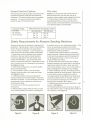
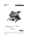
GeneralSpecifications
The Wilton Model 4210 Belt and Disc Sanding
Machine is ideal for all shops. This versatile machine
can be used to grind, sand, finish, and contour all
types of parts including metal, wood, plastic, and
composite materials. Because of these capabilities,
the Tradesman sander eliminates the need for
multiple machines to perform the same tasks.
\ I 0
0
Tradesman Belt/Disc Sander, Model 4210
Specifications
Belt Size
6" x 48"
Disc Size
10"
Motor
Horsepower
Voltage
Switch
3
1 HP
115/230Vac (pre-wiredfor 115Vac)
RemovableSafety Key
Platen
Cast Iron
Tables
Cast Iron (2)
Belt Speed
5000 SFPM
Dust CollectionShrouds
Two(standard)
Weight
120 Ibs.
General Machinery Cautions
- Misuse of this machine can cause serious injury.
- For safety, machine must be set up, used and
serviced properly.
- Read, understand and follow instructions in the
operator's and parts manual which was shipped with
your machine.
When setting up machine:
- Always avoid using machine in damp or poorly
lighted work areas.
- Always be sure machine is securely anchored to the
floor.
- Always keep machine guards in place.
- Always put start switch in "OFF" position before
plugging in machine.
When using machine:
- Never operate with machine guards missing.
- Always wear safety glasses with side shields (See
ANSI Z87.1)
- Never wear loose clothing or jewelry.
- Never overreach - you may slip and fall into the
machine.
- Never leave machine running while you are away
from it.
- Always shut off the machine when not in use.
When servicing machine:
- Always unplug machine from electrical power while
servicing.
- Always follow instructions in operators and parts
manual when changing accessory tools or parts.
- Never modify the machine without consulting Wilton
Corporation.
You - the stationary power tool user - hold the key to safety.
Read and follow these simple rules for best results and full benefits from your machine. Used properly, Wilton's
machinery is among the best in design and safety. However, any machine used improperly can be rendered
inefficient and unsafe. It is absolutely mandatory that those who use our products be properly trained in how to
use them correctly. They should read and understand the Operators and Parts Manual as well as all labels
affixed to the machine. Failure in following all of these warnings can cause serious injuries.
Machinery general safety warnings
4
1. Always wear protective eye wear when operating
machinery. Eye wear shall be impact resistant,
protective safety glasses with side shields which
comply with ANSI Z87.1 specifications. Use of eye
wear which does not comply with ANSI Z87.1 specifications could result in severe injury from breakage of
eye protection.
2. Wear proper apparel; no loose clothing or jewelry
which can get caught in moving parts. Rubber soled
footwear is recommended for best footing.
3. Do not overreach. Failure to maintain proper
working position can cause you to fall into the
machine or cause your clothing to get caught pulling you into the machine.
4. Keep guards in place and in proper working order.
Do not operate the machine with guards removed.
5. Avoid dangerous working environments. Do not
use stationary machine tools in wet or damp
locations. Keep work areas clean and well lit.
6. Avoid accidental starts by being sure the start
switch is "OFF" before plugging in the machine.
7. Never leave the machine running while unattended.
8. Disconnect electrical power before servicing.
Whenever changing accessories or general maintenance is done on the machine, electrical power to the
machine must be disconnected before work is done.
9. Maintain all machine tools with care. Follow all
maintenance instructions for lubricating and the
changing of accessories. No attempt shall be made
to modify or have makeshift repairs done to the
machine. This not only voids the warranty but also
renders the machine unsafe.
10. Machinery must be anchored to the floor.
11. Secure work. Use clamps or a vise to hold work,
when practical. It is safer than using your hands and
it frees both hands to operate the machine.
12. Never brush away chips while the machine is in
operation.
13. Keep work area clean. Cluttered areas invite
accidents.
14. Remove adjusting keys and wrenches before
turning machine on.
15. Use the right tool. Don't force a tool or attachment to do a job it was not designed for.
16. Use only recommended accessories and follow
manufacturers instructions pertaining to them.
17. Keep hands in sight and clear of all moving parts
and cutting surfaces.
18. All visitors should be kept at a safe distance from
the work area. Make workshop completely safe by
using padlocks, master switches, or by removing
starter keys.
19. Know the tool you are using - its application,
General Electrical Cautions
Wire sizes
This machine should be grounded in accordance with
the National Electrical Code and local codes and
Caution: for circuits which are far away from the
electrical service box, the wire size must be increased in order to deliver ample voltage to the motor.
To minimize power losses and to prevent motor
overheating and burnout, the use of wire sizes for
branch circuits or electrical extension cords according
to the following table is recommended:
ordinances. This work should be done by a qualified
electrician. The machine should be grounded to
protect the user from electrical shock.
Conductor length
U-bUTeet
50-100 feet
Over 100 feet
AWG (American wire gauge) number
120 volt lines
240 volt lines
No. 14
No. 14
No. 12
No. 14
No.12
NO.8
Safety Requirements for Abrasive Sanding Machines
Abrasive sanding can be hazardous to operators and
bystanders. Sanding sparks, chips and dust particles
thrown off by the sanding disc can cause serious
injury by contact or inhalation. To avoid injuries you
must comply with the following safety requirements:
1. Always wear protective eyewear when operating
machinery. Eye wear shall be impact resistant,
protective safety glasses with side shields which
comply with ANSI Z87.1. Use of eye wear which
does not comply with ANSI Z87.1 specifications could
result in severe injury from breakage of eye protection.
See Figure A, below.
2. Wear leather safety gloves, arm guards, leather
aprons and safety shoes.
3. A dust collection system is recommended,
Operator shall also wear a dust mask at all times.
See Figure B, below.
4. Additional precautions may be necessary for
sanding materials which are flammable or have other
hazardous properties. You should always consult the
manufacturer of such materials for instructions on
sanding and handling.
5. Do not force or jamb the workpiece into the
sanding disc.
6. Before sanding, always allow the motor to come
up to operating speed, then check the sanding disc
Figure A
FigureB
for wobble, runout, or any unbalanced condition. If the
disc is not operating accurately and smoothly,
immediately stop the motor and make repairs before
attempting any sanding operations.
7. Abrasive discs must be stored in a controlled
environment area. Relative humidity should be 35%
to 50% and the temperature should be between 60
and 80 degrees Farenheit. Failure to do so could
cause premature disc failure.
8. Examine the face of the sanding disc carefully.
Excessive sanding which wears down to the backing
material can tearing of the disc. Never use a disc
which shows backing, nicks or cuts on the surface or
edge or damage due to creasing or poor handling.
9. When installing a new disc, be certain the disc is
accurately centered on the drive wheel. Failure to do
so could cause a serious unbalanced condition.
10. Always present the workpiece to the wheel while
resting the workpiece firmly on the table. Failure to
do so could result in damage to the workpiece or
throwing of the workpiece off the wheel.
11. Safety shoes which comply with ANSI Z41.1 shall
be worn. See Figure C.
12. Personal hearing protection such as ear plugs or
ear muffs shall be used to protect against the effect of
noise exposure. See Figure D.
Figure C
Figure D
5
Introduction
This manual includes operating and maintenance
instructions for the Wilton Model 4210 Belt and Disc
Sander. This manual also includes parts listings and
illustrations of replaceable parts.
Beltand DiscSander
Features
Sanding Belt
Belt Guard
Belt Sander
Work Table
Platen Housing
Figures 1 and 2 depict the main features of the Wilton
Model 4210 Belt and Disc Sander. (Specifications for
the sanding machine are provided on page 3.)
Machine
Base
Tracking Adjustment
0
0
Stand
Figure 2: Belt and Disc Sander Features
(Left Side View)
6
The sander has both a sanding belt and a sanding
disc for use on a variety of work pieces and materials.
0
0
Disc Work
TableClamping
Knob
Figure 1: Belt and Disc Sander Features
(Right Side View)
The platen housing for the belt sander can be positioned vertically or horizontally. When in the vertical
position, the drum at the upper end of the platen
housing can be used for contouring. A tracking
adjustment mechanism for the sanding belt is provided at the upper end of the platen housing.
The platen housing has a lever that is used to apply
tension to the sanding belt. The sanding belt is easily
replaced by releasing the tension lever, removing a
sanding shroud and dust collection duct at the bottom
of the platen housing, and slipping the belt from the
belt sander drums. Installation is the reverse of the
removal steps.
The disc sander consists of an aluminum disc onto
which is installed an adhesive-backed sanding and
other abrasive discs. The disc is contained within a
ducted shroud.
The sanding disc can be replaced by removing the
table and a cover over the lower portion of the disc. If
desired, the aluminum disc can be removed from its
drive shaft to ease replacement of the sanding disc.
The drive motor for the belt and disc sander is attached to the underside of the machine base. An aNI
OFF switch is mounted on the machine base on the
side opposite the disc sander. Electrical wiring for
the motor enters the machine base below the aNI
OFF switch and is routed to the switch and motor
inside the machine base.
The belt and disc sander is driven by V-belts connected to the drive motor. A pulley on the motor shaft
drives a V-belt that drives a dual-groove pulley on an
idler shaft. A second V-belt is installed in the second
groove of the dual-groove pulley and connects to a
pulley on belt sander drive shaft.
Installationand Setup
Mounting
It is recommended that the belt and disc sander be
secured to the floor for safe operation. The machine
stand has mounting holes in a flange on the inside of
stand enclosure. The stand can be secured to the
floor using these mounting holes.
Electrical Connection
Refer to the Wiring Data section for wiring
information. Electrical power should be connected by
a qualified electrician. Observe local electrical codes
when connecting and grounding the machine.
The aluminum sanding disc is driven off the end of the
idler shaft. A shaft connected to the second V-belt
pulley drives the belt sander drive drum.
The belt and disc sander is mounted on a stand that
can be secured to the floor to stabilize the machine.
The stand has a door for access to the fasteners for
the machine base.
7
Operation
This section defines the controls and other features
with which the operator should be familiar. Refer to
Figures 3 and 4 for some typical sander operations.
m
@
@)
Figure 5. ON/OFF Switch
Miter Gauge
A miter gauge is provided with the machine and can
be used on either the belt sander of disc sander work
tables. The angle of the miter gauge can be adjusted
up to 45 degrees to accommodate angular work piece
surfaces.
Adjustments
Adjusting Belt Tracking
Figure 3. Contouring with Belt Sander
The tracking of the sanding belt may require adjustment after changing the belt. The belt housing has a
tracking adjustment mechanism (Figure 6) that is
used to adjust tracking.
1. Start the machine.
2. Check tracking of the sanding belt. The belt
should track at the center of the drums.
3. Adjust belt tracking by turning the adjustment
knob. Turn the knob as needed to correct the
tracking of the belt.
8
Belt should track
at center of
drums; no side-toside movement.
:::--.
--'-
Figure 4. Sanding using Disc Sander
Controls
The ON/OFF switch is located on the side of the
machine base (refer to Figure 5).
---------------
Figure 6. Adjusting Belt Tracking
AdjustingPlaten Housing
Position
The sanding belt can be operated with the platen
housing horizontal, vertical, or at any angle in
between. Change position of the platen housing as
follows:
Disc Table
1. To change the disc table angle, loosen the knob
on the left side of the table (refer to Figure 8).
2. Movethe table to the desired angle.
3. Tighten the knob to secure the table.
WARNING: DISCONNECT ELECTRICAL POWER
TO THE MACHINE BEFORE PERFORMING ANY
MAINTENANCE.
1. Disconnectelectrical power.
2. Removefour screws (52)and pulleycover (12).
3. Using an open end wrench, loosentwo hex
screws (13) (refer to Figure7).
4. Movethe platen housingto the desired position.
When the platen housing is to be placed in the
horizontalposition, lower the platen housingonto
stop screw (28) on the machine base.
5. If the stop requiresadjustment, loosenjam nut
(29), adjust stop screw (28) to desired position,
and tighten nut (29).
6. Tighten two hex screws (13).
7. Install pulleycover (12) and securewith four
screws (52).
8. Start the machine to check operation.
Table Clamping Knob
Figure 8. Adjusting Sander Table Angle
Belt Table
Clamping
Screws
Figure 7. Platen Housing Clamping Screws
Adjusting the Sander Tables
The belt and disc sander tables can be adjusted
from 0 to 45 degrees to accommodate the work
piece.
1. To change the belt table angle, loosenthe knob
on the right side of the platen housing (refer to
Figure8).
2. Move the table to the desired angle.
3. Tighten the knob to secure the table.
9
Maintenance
This section provides proce~ures required to maintain
the belt/disc sander. The numbers in parentheses
throughout the manual correspond with reference
numbers for parts shown in the exploded views in the
Replacement Parts section.
Lubrication
The bearings used in the sanding machine are sealed,
pre-lubricated bearing. The bearings do not require
periodic lubrication.
Positionedges of sanding belt evenly on the
drums.
2. Lift tensioning lever to tighten sanding belt on
drums.
3. Install guard (75) and secure with screw (76).
4. Install guard (96) and secure with eight screws
(97).
5. Connect electricalpower and operate machineto
check operation.
6. If belt does not track properly, adjust tracking
(refer to Adjusting Belt Tracking).
Replacing the Sanding Disc
WARNING: DISCONNECT ELECTRICAL POWER
TO THE MACHINE BEFORE PERFORMING ANY
MAINTENANCE.
Cleaning
Periodically use a vacuum cleaner to remove sanding
debris from the machine. In hard to reach areas,
brush the debris loose while vacuuming.
Replacing the Sanding Belt
WARNING: DISCONNECT ELECTRICAL POWER
TO THE MACHINE BEFORE PERFORMING ANY
MAINTENANCE.
1. Disconnectelectrical power.
2. Positionsanding belt platen (4) in the vertical
position. Remove eight screws (97) and guard
(96).
3. Removescrew (76)and guard (75).
4. Movetensioninglever (50)downwardto slacken
sanding belt (79).
10
1. Installreplacementsandingbelton drums.
1. Disconnectelectrical power.
2. Loosenscrew (65). Removedisc table (60).
3. Removefour screws (56)and plate (55) from disc
shroud(53).
4. Inserta long T-handleAllen wrench through the
side opening in shroud (53) and into set screw
(57). Loosen disc set screw (57) and remove disc
(58).
WARNING:
USE CARE WHEN USING KNIFE TO
SEPARATE SANDING DISC (59) FROM DISC (58).
INJURY FROM THE KNIFE MAY OCCUR IF THE
KNIFE SLIP OR IF SANDING DISC SHOULD SUDDENLY COME FREE.
5.
Refer to Figure 9. Slip sanding belt off drums (5) and
(39).
6.
7.
8.
Using a knife, slowly work the tip of the knife
blade under sanding disc (59). Slowly work the
tip around the circumference of disc (58). Continue to work around the circumference until
sanding disc can be separated by hand from disc
(58).
Remove paper backing from replacement sanding
disc (59). Place sanding disc (59) on disc (58).
Make sure the sanding disc is place evenly at the
outside diameter of disc (58).
Press on the sanding disc to remove any entrapped air and to make sure the sanding disc is
adhering to disc (58).
Install disc (58) onto shaft (16). Position the disc
on the shaft to provide clearance between plate
(55) and sanding disc. Tighten set screw (57).
--.
[
Figure 9. Replacing Sanding Belt
NOTE: There is a close fit between the edge of disc
(58) and disc shroud. To ease installation and positioning of the disc, use an L-shaped tool (such as an
Allen wrench) under outer edge of the disc to support
and position the disc while tightening set screw.
9.
Install plate (55) and secure with four screws (56).
Check for clearance between plate (55) and the
sanding disc.
10. Install table (60) onto rod (74). Position table so
it is level and tighten screw (65) against rod (74).
11. Connect electrical power and operate machine to
check operation.
Replacing the V-Belts
WARNING: DISCONNECT ELECTRICAL POWER
TO THE MACHINE BEFORE PERFORMING ANY
MAINTENANCE.
1.
2.
3.
4.
5.
6.
Disconnectelectrical power.
Removesandingbelt table.
Removesandingdisc table.
Removesandingdisc and shroud.
Remove pulley cover. Loosen set screw in pulley.
With second person holding belt housing, alternately loosen and removetwo screws.
7. RemoveV-beltfrom pulley (11). Removepulley
from shaft while separatingassembled belt
housingfrom the machine base.
8. Removekey from sandingbelt drum shaft.
9. Loosen set screw in pulley (20).
10. Remove pulley.While removingpulley, slip Vbelts from pulley.
11. Removefour screws from base. With assistance
of the second person, lift base from stand.
NOTE: Place base on bench. As an alternative, the
stand may be used to support the base while removing drive motorscrews.
12. Place base on bench with underside of the base
facing up.
13. Remove two hex head screws, two nuts, and two
washers from the motor base on the shaft side of
motor.
14. Loosen (but do not remove) two hex bolts, two
nuts, and two washers on the side of motor base
opposite the motor shaft.
15. Tip motor enough to provide clearance between
end of shaft and wall of base. Remove motor
drive belt.
16. With base still on the bench, slip V-belt (15) over
end of idler shaft.
NOTE: Install V-belt for sanding belt first, followed by
the motor V-belt.
17. Install replacement V-belt over end of motor shaft.
18. Install two hex bolts, two nuts, and two washers
in the motor base on the shaft side of motor.
Tighten all four hex nuts and hex head screws.
19. Install key in idler shaft with keyway facing up.
Install pulley (20) on idler shaft.
20. Install motor V-belt (18) in outermost groove of
pulley (20) and on pulley (18) on motor shaft.
21. Position motor belt (18) on idler shaft so it is
parallel with the inner wall of the base. Tighten
set screw in pulley (20).
22. Place assembled base on stand. Secure with
four screws, washers, nuts.
NOTE: Because of the weight of the belt housing, a
second person should hold the belt housing in
position while installing pulley (10).
23. Hold belt housing in position in bracket (3). Start
two screws (13) in threaded holes in platen.
Install key (8) in shaft.
NOTE: Because of the length of screws (13), the
screws will have to be installed alternately. As the
screws are installed, there will be enough clearance
to slide the belt drum drive pulley a little at a time
onto shaft (8).
24. Alternately install two screws (13). As the
screws are tightened, slide pulley (10) onto the
idler shaft as allowed by the protrusion of screw
heads. Make sure V-belt remains on pulleys (11
and 20).
25. When screws (13) are fully installed, align pulley
(20) with pulley (11). Tighten set screw (10).
26. Install shroud (53) on base and secure with four
screws and washers.
27. Install pulley cover (12) and secure with two
screws.
28. Install disc (58) onto shaft (16) and over key.
Position the disc on the shaft to provide clearance
between plate (55) and the sanding disc. Using
long T-handle Allen wrench, tighten set screw
(57).
NOTE: There is a close fit between the edge of disc
(58) and the disc shroud. To ease installation and
positioning of the disc, use an L-shaped tool (such as
an Allen wrench) under the outer edge of the disc to
support and position the disc while tightening the set
screw.
29. Install plate (55) and secure with four screws (56).
Check for clearance between plate (55) and the
sanding disc.
30. Install table (60) onto rod (74). Position table so
it is level and tighten screw (65) against rod (74).
31. Install assembled table (88).
32. Connectelectricalpowerandoperatemachineto
11
checkoperation.
Replacement of Motor
WARNING: DISCONNECT ELECTRICAL POWER
TO THE MACHINE BEFORE PERFORMING ANY
MAINTENANCE.
1. Disconnectelectrical power.
2. Removefour screws from base. With assistance
of the second person, lift base from stand.
NOTE: Place base on bench. As an alternative,the
stand may be used to support the base while removing drive motor screws.
3.
Place base on bench with underside of the base
facing up.
Remove four hex head screws, nuts, and washers
from the motor base.
5. Remove motor V-belt from motor pulley.
6. Remove motor from base.
7. Loosen set screw in pulley (18). Remove pulley.
8. Align set screw in pulley with flat on motor shaft
and install pulley. Do not tighten set screw.
9. Install replacement V-belt over end of motor shaft
and install motor in base. Secure with four
screws, washers and nuts.
10. Install and tighten four hex bolts, nuts, and
washers in the motor base.
4.
11. Position pulley (18) on motor shaft so the V-belt
is parallel with the inner wall of the base. Tighten
set screw in pulley (20) against flat on motor
shaft.
12. Place assembled base on stand. Secure with
four screws, washers, nuts.
13. Connect electrical power and operate machine to
check operation.
12
Troubleshooting
Fault
Probable Cause
Remedy
Machine does not start.
1. Blown fuse or tripped
circuit breaker.
2. Motor failure.
3. Not connected to power
source.
4. Motor not wired for correct
1. Determine reason for blown fuse/tripped
breaker (such as a short circuit or motor
overload). Correct reason for fault.
Replace fuse/ reset breaker.
2. Replace motor.
3. Connect to power source.
4. Correct motor wiring.
5. Connect to proper voltage source.
voltage.
5. Motor not connected to
correct voltage source.
Sanding belt does not
track correctly.
1. Sanding belt stretched
unevenly.
2. V-belt worn.
1. Replace sanding belt.
2. Replace V-belt.
3. Replace pulley.
3. Pulley worn.
1. Clean residual adhesive from disc.
Abrasive disc separates
from disc.
1. Improperly bonded.
Sanding belt slips or stalls
when pressure is applied.
1. Abrasive belt tension
Disc stalls when pressure
is applied.
1. Motor V-belt loose.
1. Tighten motor V-belt.
Frequent replacement of
sanding belt.
1. Too much pressure being
applied to work piece.
2. Full width of belt not being
used.
1. Reduce pressure on work piece.
2. Stroke across sanding belt using full width
of belt surface.
Reapply adhesive-backed disc to clean disc.
inadequate.
2. Excessive pressure being
applied to platen housing.
3. Motor belt loose.
1. Tighten sanding belt.
2. Reduce pressure on sanding belt
(and platen housing).
3. Tighten motor belt.
13
WiringData
Single phase electrical hook-up
When connecting your machine to single phase
power you may be connecting to either 115 or 230
volts, depending upon the motor type provided. Local
codes may, or may not, permit the use of a plug type
of connection for your machine. Where a plug
connection is permitted, the following installation
practices must be followed:
1. The plug used must be a grounding type of plug.
On a 115 volt single phase connection, the plug
must be a three-prong plug with two flat, parallel
blades for the power wires and a single rounded
or U-shaped prong for the ground connection. On
230 volt single phase connections, the lug must
be a three prong plug with two flat blades in
tandem to carry the current, and a third round or
U-shaped prong for the ground connection.
2. The service branch to which the plug is connected
must be a branch with a separate ground wire so
the grounding prong of the plug can be connected
to ground effectively.
Note: Local electrical codes in many jurisdictions do
not allow the use of plug type connections for single
phase power when the machine is used in a commercial or industrial establishment.
In these cases you must connect your machine to
the service branch using a hard-wired junction box
connection.
All Wilton sanders are shipped with the power cable
terminating without a plug on the assumption the
machine will be hard-wired to its service branch.
Circuit protection
Where the service branch is protected with a fuse or
circuit breaker which is too high a value to offer
protection to the motor supplied, a fuse or circuit
breaker box should be used at the point where the
machine connection is made and the time delay fuse
or circuit breaker should be a value just slightly higher
than the maximum load current draw as specified on
the motor plate on the motor.
Correcting motor rotation in single
phase motors
Wilton provides single phase motors in both 115 volt
and 230 volt configuration. Several motor manufactures may be used by Wilton for motors of this type.
These motors may, or may not, rotate in the correct
direction -- counter-clockwise-- when connected to
your single phase power source. If, after connection,
the motor runs in the correct counter-clockwise
direction, the power connection is successful.
Switch
White
14
Figure 10: Pictoral diagram for single
phase motor, 115 volts w/plug.
Switch
'-
'-r -White-
Figure 11: Pictoral diagram for
3-phase motor.
CAUTION: IF THE MOTOR RUNS CLOCKWISE
WHEN CONNECTED TO YOUR SINGLE PHASE
POWER SOURCE, YOU MUST DISCONNECT THE
POWER SOURCE, OPEN THE JUNCTION BOX AND
FIND THE CORRECT WIRING CONNECTIONS FOR
THE MOTOR, OR LOCATE THE WIRING CONNECTIONS REQUIRED ON THE MOTOR PLATE ON THE
OUTSIDE OF THE MOTOR.
Different manufacturers provide different wiring
configurations for correcting the rotation of the motor
armature. Therefore, no wiring diagrams for these
motors are provided in this manual. Always consult
the motor plate and/or the wiring diagram inside the
junction box if rotation direction is not correct.
Connecting Power for 3-phase
Motors
1. Be certain the power to the branch you are
connecting is off, and locked out, so power
cannot be reestablished, accidentally.
2. Connect the ground wires. Thse wires will be
either green, or green with a white trace.
3. Connect the remaining three cable wires to the
three power wires in the service branch.
4. Reestablish power to the branch.
5. Turn the machine on. The motor should be turning
counter-clockwise, the belt sander should be
Motor
Switch
7.
8.
9.
Green or
green with
white trace
Single
phase
power
in
M
Motor
6.
moving downward, and the disc sander should be
turning clockwise. If this is the case, the machine can be considered wired correctly. If the
motor is not turning in the correct direction, take
the following corrective action:
Disconnect power in the branch again and be
certain it cannot be accidentally turned on while
you correct the wiring.
Reverse ANY TWO of the power wires to the
machine.
Reestablish power in the service branch to the
machine.
Turn on the machine again. The motor should now
be turning in the correct direction.
Figure 12: Schematic diagram for
single phase motor with 3-wire
cable. Note:this schematic
providedfor use with older
sanders, only. All machinesare
now shipped with a 4-wire cable
whether single phase or 3-phase.
Switch
Figure 13: $chematic diagram for
single phase motor with 4-wire
cable.
15
Unused switch
pole
Motor
Switch
4-pole cable to
junction box
Figure 14: Schematic diagram for
3-phase motor.
ReplacementParts
This section provides exploded view illustrations that show the replacement parts for the Tradesman Model 4210
BelVDisc Sander. Also provided are parts listings that provide part number and description. The item numbers
shown on the illustration relate the item number in the facing parts listing.
Order replacement parts from:
Wilton Corporation
300 South Hicks Road
Palatine, IL 60067
847/934-6000
FAX: 847/934-7813 or 1-800-626-9676
Identify the replacement part by the part number shown in the parts listing. Be sure to include the model
number and serial number of your machine when ordering replacement parts to assure that you will receive the
correct part.
16
Assembled View of Stand - Model 4210
Beltand Disc Sander
3
Parts Listing - Model 4210 Beltand DiscSander Stand
17
Ref.
No.
Part
Number
Description
Qty.
1
2
3
5513476
5513477
5513478
Panel, Access
Knob
Enclosure, Stand
1
2
4
ExplodedView- TradesmanModel4210 Belt& Disc
Sander
c"",,
78
18