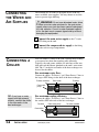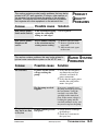
1
WARNING - Reliance on this Manual Could Result in Severe Bodily Injury or Death!
This manual is out-of-date and is provided only for its technical information, data and capacities. Portions of this manual
detailing procedures or precautions in the operation, inspection, maintenance and repair of the product forming the subject
matter of this manual may be inadequate, inaccurate, and/or incomplete and cannot be used, followed, or relied upon.
Contact Conair at [email protected] or 1-800-654-6661 for more current information, warnings, and materials about
more recent product manuals containing warnings, information, precautions, and procedures that may be more adequate
than those contained in this out-of-date manual.
Please record your
equipment’s model and
serial number(s) and
the date you received it
in the spaces provided.
It’s a good idea to record the model and serial number(s) of
your equipment and the date you received it in the User
Guide. Our service department uses this information, along
with the manual number, to provide help for the specific
equipment you installed.
Please keep this User Guide and all manuals, engineering
prints and parts lists together for documentation of your
equipment.
Date:
Manual Number:
UGE014/0999
Serial number(s):
Model number(s):
DISCLAIMER: The Conair Group, Inc., shall not be liable for errors
contained in this User Guide or for incidental, consequential damages in connection with the furnishing, performance or use of this
information. Conair makes no warranty of any kind with regard to
this information, including, but not limited to the implied warranties
of merchantability and fitness for a particular purpose.
Copyright 1999
THE CONAIR GROUP, INC.
All rights reserved
INTRODUCTION . . . . . . . . . . . . . . . . . . .1-1
Purpose of the User Guide . . . . . . . . . . . . . . . . . . . . . . . . .1-2
How the guide is organized . . . . . . . . . . . . . . . . . . . . . . . .1-2
Your responsibilities as a user . . . . . . . . . . . . . . . . . . . . . .1-2
ATTENTION: Read this so no one gets hurt . . . . . . . . . . .1-3
TABLE OF
CONTENTS
DESCRIPTION . . . . . . . . . . . . . . . . . . . .2-1
What is the WT and ST tank? . . . . . . . . . . . . . . . . . . . . . .2-2
How it works . . . . . . . . . . . . . . . . . . . . . . . . . . . . . . . . . . .2-3
Specifications . . . . . . . . . . . . . . . . . . . . . . . . . . . . . . . . . .2-4
Features and Options . . . . . . . . . . . . . . . . . . . . . . . . . . . . .2-5
INSTALLATION . . . . . . . . . . . . . . . . . . . .3-1
Unpacking the boxes . . . . . . . . . . . . . . . . . . . . . . . . . . . . .3-2
Preparing for installation . . . . . . . . . . . . . . . . . . . . . . . . . .3-3
Aligning the tank . . . . . . . . . . . . . . . . . . . . . . . . . . . . . . . .3-4
Connecting the main power . . . . . . . . . . . . . . . . . . . . . . . .3-5
Connecting the water and air supplies . . . . . . . . . . . . . . . .3-6
Connecting a chiller . . . . . . . . . . . . . . . . . . . . . . . . . . . . . .3-7
Testing the installation . . . . . . . . . . . . . . . . . . . . . . . . . . . .3-8
OPERATION . . . . . . . . . . . . . . . . . . . . . .4-1
Preparing for operation . . . . . . . . . . . . . . . . . . . . . . . . . . .4-2
Starting the WT/ST tank . . . . . . . . . . . . . . . . . . . . . . . . . .4-4
Stopping the WT/ST tank . . . . . . . . . . . . . . . . . . . . . . . . .4-4
MAINTENANCE . . . . . . . . . . . . . . . . . . . .5-1
Preventative maintenance schedule . . . . . . . . . . . . . . . . . . .5-2
Replacing gaskets . . . . . . . . . . . . . . . . . . . . . . . . . . . . . . .5-3
Lubricating the tank compartments . . . . . . . . . . . . . . . . . .5-3
Cleaning the tank and spray bars . . . . . . . . . . . . . . . . . . . .5-3
Checking electrical connections . . . . . . . . . . . . . . . . . . . . .5-4
TROUBLESHOOTING . . . . . . . . . . . . . . . .6-1
Before beginning . . . . . . . . . . . . . . . . . . . . . . . . . . . . . . . .6-2
A few words of caution . . . . . . . . . . . . . . . . . . . . . . . . . . .6-2
Product quality problems . . . . . . . . . . . . . . . . . . . . . . . . . .6-3
Water system problems . . . . . . . . . . . . . . . . . . . . . . . . . . .6-3
APPENDIX
Customer service . . . . . . . . . . . . . . . . . . . . . . . . . . . . . . .A-1
Warranty information . . . . . . . . . . . . . . . . . . . . . . . . . . . .A-2
UGE014/0999
Water/Spray Tanks
i
INTRODUCTION
● Purpose of the User Guide . . . .1-2
● How the guide is organized . . . .1-2
● Your responsibilities as a user .1-2
● ATTENTION: Read this so
no one gets hurt . . . . . . . . . . .1-3
UGE014/0999
Water/Spray Tanks
1-1
PURPOSE OF
THE USER
GUIDE
This User Guide describes the Conair WT and ST series
water/spray tanks. It explains step-by-step how to install,
operate, maintain and repair this equipment.
HOW THE
GUIDE IS
ORGANIZED
Symbols have been used to help organize the User Guide and
call your attention to important information regarding safe
installation and operation.
YOUR
RESPONSIBILITY
AS A USER
Before installing this product, please take a few moments
to read the User Guide and review the diagrams and safety
information in the instruction packet. You also should review
manuals covering associated equipment in your system. This
review won’t take long, and it could save you valuable installation and operating time later.
!
Symbols within triangles warn of conditions that could
be hazardous to users or could damage equipment.
Read and take precautions before proceeding.
1
Numbers within shaded squares indicate tasks or steps
to be performed by the user.
◆
A diamond indicates the equipment’s response to an
action performed by the user.
❒
●
An open box marks items in a checklist.
A shaded circle marks items in a list.
You must be familiar with all safety procedures concerning
installation, operation and maintenance of this equipment.
Responsible safety procedures include:
● Thorough review of this User Guide, paying particular
attention to hazard warnings, appendices and related
diagrams.
● Thorough review of the equipment itself, with careful
attention to voltage sources, intended use and warning
labels.
● Thorough review of instruction manuals for associated
equipment.
● Step-by-step adherence to instructions outlined in this
User Guide.
1-2
INTRODUCTION
Water/Spray Tanks
UGE014/0999
We design equipment with the user’s safety in mind. You can
avoid the potential hazards identified on this machine by
following the procedures outlined below and elsewhere in
the User Guide.
!
ATTENTION:
READ THIS
SO NO
ONE GETS HURT
WARNING: Improper installation,
operation or servicing may result in
equipment damage or personal injury.
This equipment should be installed, adjusted,
and serviced by qualified technical personnel
who are familiar with the construction, operation and potential hazards of this type of
machine.
All wiring, disconnects and fuses should be
installed by qualified electrical technicians in
accordance with electrical codes in your region.
Always maintain a safe ground. Do not operate
the equipment at power levels other than what
is specified on the the machine serial tag and
data plate.
You should keep the area around the tank
clean and free from pooling water. We recommend installing a grate or drain system beneath
this equipment to prevent water from pooling
around the tank.
WARNING: Voltage hazard
This equipment is powered by three-phase
alternating current, as specified on the machine
serial tag and data plate.
A properly sized conductive ground wire from
the incoming power supply must be connected
to the chassis ground terminal inside the electrical enclosure. Improper grounding can result
in severe personal injury and erratic machine
operation.
Always disconnect and lock out the incoming
main power source before opening the electrical enclosure or performing non-standard operating procedures, such as routine maintenance.
Only qualified personnel should perform troubleshooting procedures that require access to
the electrical enclosure while power is on.
UGE014/0999
Water/Spray Tanks
INTRODUCTION
1-3
DESCRIPTION
● What is a WT or ST tank? . . . . .2-2
● How it works . . . . . . . . . . . . . . .2-3
● Specifications . . . . . . . . . . . . . .2-4
● Features and options . . . . . . . . .2-5
UGE014/0999
Water/Spray Tanks
2-1
WHAT IS THE
WT OR ST
TANK?
Conair Water and Spray Tanks are designed to provide additional spray or flood cooling of extruded profiles, tubing and
pipe, or as a primary spray or cooling tank. Leveling floor
jacks and adjustment handwheels at both ends of the tank
ensure proper alignment with the extrusion line.
After an extrusion has been sized and solidified, it may
require additional controlled cooling to obtain the desired
characteristics.
The WT water tank provides flood cooling. You can submerge the extrusion in heated water to slow the cooling rate,
or in cool water to cool it more quickly. The internal plumbing
configuration for flood cooling is designed to provide maximum turbulence to break up the temperature strata that forms
around the extrusion for optimum heat transfer. Support and
hold-down rollers keep the buoyant extrusion in place as it
passes through the tank.
The ST spray tank reduces the buoyancy of the extrusion in
the water and provides maximum heat transfer through evaporation by spraying water onto the hot extrusion surface. The
extrusion can be held above the water level or submerged in
the water in the spray compartment.
Both WT and ST tanks have two compartments: a long water
or spray compartment for controlled cooling of the extrusion,
and a short air-wipe compartment for removing water from the
pipe surface as it leaves the water or spray compartment.
The water and spray compartments are sealed by gaskets on
each end. Black wiping gaskets backed up by red support
gaskets retain the flood and spray water.
An optional closed water recirculation reservoir, pump and
heat exchanger can interface with your portable chiller or central chiller for reduced water consumption.
2-2
DESCRIPTION
Water Spray Tanks
UGE014/0999
The extrusion enters the water or spray compartment after
leaving the calibration tooling or a sizing tank. Simple support
and hold-down rollers ar used to hold small diameter hollow
forms in position as the extrusion passes through the tank.
Contoured support and hold-down rollers usually are required
for large hollow forms.
HOW IT WORKS
In a WT water tank, the extrusion is submerged in a flooded
water compartment. Water enters the compartment through a
quick fill valve or through one center-supply, drilled water
header that is mounted along the top and back side of the
compartment. The water level is controlled by a telescoping
overflow standpipe.
In the ST spray tank, the extrusion may be submerged or
held above the water.
All water enters the compartment
through four center-supply water
headers mounted at the four
corners along the full length of the
compartment. These water headers
are drilled or equipped with spray
heads. Each pair of spray headers
has its own water supply valve.
Water levels are controlled by the
setting of the standpipe. When set
low, the standpipe keeps the water
level below the extrusion. When set
high, the standpipe allows complete submersion of the extrusion
in a flooded compartment.
The extrusion passes from the water or spray compartment
into an air-wipe compartment equipped with two, tubular air
wiper rings connected to compressed air. Angled holes drilled
in the wiper ring blasts air on the extrusion in the direction of
the extruder to blow off surface water. A gasket seal at the
exit of the air wipe compartment ensures the extrusion will be
dry as it reaches the puller.
UGE014/0999
Water/Spray Tanks
DESCRIPTION
2-3
SPECIFICATIONS
A
B
V caster width
D
22 in. {56 cm}
C
MODEL
TANK STYLE
Performance characteristics
Tube/profile diameter in. {cm}
Tank cross section in. {cm}
Water flow gpm {liters/sec}
Dimensions inches {cm}
A - Overall height
B - Height to centerline‡
C - Overall length
D - Tank length
E - Overall width
Weight lbs {kg}
Shipping
Water requirements
Compressed air requirements
MODEL
TANK STYLE
Performance characteristics
Tube/profile diameter in. {cm}
Tank cross section in. {cm}
Water supply flow gpm {liters/sec}
Dimensions inches {cm}
A - Overall height
B - Height to centerline‡
C - Overall length
D - Tank length
E - Overall width
Weight lbs {kg}
Shipping
Water requirements
Compressed air requirements
104-12--2
E
WT104
104-16-2
104-21-2
WT105-12-2
up to 2 {5.1}
8 x 8 {20.3 x 20.3}
35 {2.7}
52 {132}
42 {107}
156 {396}
144 {366}
26.5 {67}
52 {132}
42 {1067}
204 {518}
192 {468}
26.5 {67}
WT/ST105*
105-16-2
105-21-2
up to 4.5 {11.4}
12 x 12 {30.5 x 30.5}
35 {2.7}
52 {132}
42 {1067}
264 {671}
252 {640}
26.5 {67}
53 {135}
42 {1067}
156 {396}
144 {366}
26.5 {67}
53 {135}
42 {1067}
204 {518}
192 {468}
26.5 {67}
53 {135}
42 {1067}
264 {671}
252 {640}
26.5 {67}
WT/ST107
107-16-2
107-21-2
up to 6.625 {16.8}
14 x 14 {35.6 x 35.6}
50 {3.8}
54 {137}
42 {1067}
204 {518}
192 {468}
26.5 {67}
54 {137}
42 {1067}
264 {671}
252 {640}
26.5 {67}
950 {430}
1050 {476} 1150 {522} 1200 {544} 1300 {590} 1400 {635} 1600 {726} 1700 {816}
80 gpm @ 60-70 psi {6.1 liters/sec @ 4.8-5.5 bars}; main supply line 1.5 in. NPT fitting
maximum consumption 5 SCFM @ 80 psi {0.38 liters/sec @ 6.1 bars}
WT/ST109
109-16-2
109-21-2
ST114
114-16-2
114-21-2
ST118
118-16-2
118-21-2
up to 8.5 {21.6}
16 x 16 {40.6 x 40.6}
60 {4.5}
up to 13 {33.0}
22 x 22 {55.9 x 55.9}
60 {4.5}
up to 18 {16.8}
26 x 26 {66 x 66}
60 {4.5}
55 {138}
42 {107}
204 {518}
192 {468}
33 {83.8}
55 {138}
42 {1067}
264 {671}
252 {640}
33 {83.8}
58 {147}
42 {1067}
204 {518}
192 {468}
33 {83.8}
58 {147}
42 {1067}
264 {671}
252 {640}
33 {83.8}
60 {152}
42 {1067}
204 {518}
192 {468}
33 {83.8}
60 {152}
42 {1067}
264 {671}
252 {640}
33 {83.8}
SPECIFICATION NOTES:
These tables define standard configurations only.
Specifications can
change without notice.
ST models come with
spray bars.
* 12-foot tank available
as WT water tank only.
† Centerline height is
adjustable ± 2 inches.
1800 {816} 1900 {862} 2100 {953} 2200 {998} 2600 {1179} 2755 {1247}
80 gpm @ 60-70 psi {6.1 liters/sec @ 4.8-5.5 bars}; 1.5 in. NPT fitting
maximum consumption 5 SCFM @ 80 psi {0.38 liters/sec @ 6.1 bars}
ELECTRICAL REQUIREMENTS: Electrical connections are required only if the optional water recirculation package
and heat exchanger is used. See wiring diagrams supplied with the equipment for voltage and amp draws.
2-4
DESCRIPTION
Water/Spray Tanks
UGE014/0999
FEATURES
OPTIONS
Hinged fiberglass cover
Stainless steel tank
(optional)
AND
Overflow
collector
Three-plane adjustment
(optional)
Air wipe
compartment
Recirculation pump
(optional)
Heat exchanger
Welded steel frame with
casters and leveling jacks
(optional)
Recirculation reservoir
(optional)
● Tank: The stainless steel, all-welded tank has two compartments: a long water or spray compartment and a short
air-wipe compartment. Spray header water connections are
stainless steel fittings welded through the tank bottom. The
air wipe compartment has two drilled copper blow-off rings
mounted concentric to the extruded product. The rings are
drilled at an angle to generate water blow-off forces opposite to the direction of extrusion flow. Air supply is
through the front sidewall of the compartment. A throttling
valve is supplied.
Bulkheads are equipped with studs for applying gaskets.
Black gaskets wipe the extruded product. Red gaskets provide dynamic sealing.
● Tank Support: The tank support system provides for
(1) accurate vertical positioning of each end of the tank to
meet centerline height requirements,
(2) for accurate horizontal positioning of each end of the
tank to meet tank centerline alignment requirements, and
(3) accurate axial positioning of the tank.
The system is comprised of two basic elements: a microheight adjusting system to move the tank up and down and
a tank cradle system that cages the tank and carries means
for horizontal and axial positioning.
● Water Supply System: Water is supplied from a short
water supply header carried on the tank. A ball valve controls water to each spray header. This valve is used to modulate water to the tank. On small water tanks with one
spray header, the second valve is used for "quick fill". On
long tanks a third ball valve directs water to an end port to
assist in "quick fill".
UGE014/0999
Water/Spray Tanks
DESCRIPTION
2-5
FEATURES AND
OPTIONS (CON.)
● Tank Drain System: All tanks have overflow stand pipes
that continuously carry modulating water to the drain without drain valving. To drain the tank quickly, one to three
drains are supplied, depending on the tank length and tank
size. Additional tank drains, controlled by gate valves,
empty into the tank drain header pipe. The header pipe,
made of rigid PVC with demented fittings, is attached to
the base frame and slopes toward the extruder.
The large drain size provides unrestricted water flow to the
plant drains or plant water recovery system.
● Casters and Wheels: The tank base is supported at all four
corners by vee grooved casters. Plain wheels are available.
● Leveling Jacks: After positioning the tank, it is necessary
to anchor the tank against line forces. Two leveling jacks
(floor locks) are provided on one side of the base, effectively anchoring the tank in place.
● Vertical Adjustment System: The tank support system is
moved vertically up and down on each end to position the
centerline and to level the horizontal plane. The cradle carrying the tank rests on micro-height adjusting plate at each
end. The cradle is caged axially by angles welded to the
micro-height plates. The small handwheel horizontally
mounted to each micro-height plate engages a worm gear to
drive a vertically mounted threaded rod. When the handwheel is rotated, that end of the tank is moved up or down.
The adjustment is self locking.
● Horizontal Adjustment Option: To allow side-to-side
positioning, the sides of the cradle are moved away from
the tank. Rotation of knobs, which drive threaded blocks
beneath the tank, moves the tank side to side.
● Axial Adjustment Option: This option allows you to
move the tank backward and forward (longitudinally) in a
precise manner, with positive locking at any position. The
tank is supported on caged solid rollers running in short
tracks to allow easy movement. Rotation of the large handwheel produces axial motion of the tank, depending on the
status of the detent arm. When the detent is disengaged, the
shaft is free to turn and the tank will move toward the
puller. When the detent is pushed in and engaged, the one
way locking action of the bearing on the shaft prohibits
shaft rotation and the tank is locked in position. The detent
must be removed if tank movement toward the puller is
desired.
2-6
DESCRIPTION
Water/Spray Tanks
UGE014/0999
● Closed Water Recirculation System Option
The system includes a reservoir (sump tank), pump and
heat exchanger. .On a closed water pump system, spray
water introduced into the tank through the spray headers is
drained to a sump tank. The water is then pumped back to
the spray water supply header for control by the header
valves. The sump tank, filled from customer's water supply,
has automatic water level control. The pump has a suction
filter inside the sump tank at the pump port. The pump is
mounted on the bottom tank frame members. Two pump
choices are available: centrifugal and gear.
The 5 Hp centrifugal pump has a capacity up to 60 GPM
at 70 PSI, and is self protecting. It can be operated without
damage with the spray header valves fully closed.
The 2 Hp gear motor has a capacity of about 16 GPM. A
relief valve on the output of the pump directs water to the
tank to protect the pump if the spray header valves are fully
closed.
FEATURES AND
OPTIONS (CON.)
● Sump Tank Option: On recirculating systems, a sump
tank holds water for the open loop systems. Bottom tank
frame members support the sump, which is caged but not
anchored. The overflow PVC drain fitting is dual purpose,
reversible. As installed, the NPTF is outboard for screwed
piping. When the fitting is reversed, external piping may be
cemented into the sweat end.
● Circulation Pump Option: A Crane circulating pump is
normally used to move tank water across the optional
immersion heating elements or optional cooling coils. The
pump is hard piped to the tank and moves with it. Water
flow is parallel to extrudate flow. The pump is operated at
120 volts through a step down transformer with the primary
at 230 or 460 volts, single phase, 60 HZ. Power requirements are about 0.5 KVA.
● Immersion Heater Option: The 230 volt, 3 kW, singlephase tubular electric heater is a self contained unit with
off-on control and a temperature setting control dial. The
unit is mounted through the sidewall of the tank and
extends into the space below the extrusion. A pump is
applied to move the tank water over the heater tubes to
modulate end-to-end water temperature. The immersion
heater is supplied direct at 230 volts but requires a 3 KVA
transformer at 460 volts. The transformer is mounted in the
lower part of the tank frame. Care must taken to ensure that
the heater tubes are always immersed during operation, and
that the heater is turned off before draining tank water.
UGE014/0999
Water/Spray Tanks
DESCRIPTION
2-7
FEATURES AND
OPTIONS (CON.)
● Cooling Coils Option: Cooling coils remove heat buildup
in water. Connections are made with bulkhead fittings
through the rear wall of the tank, slightly above the high
water level. Inlet and outlet connections are close together
for easy connection to chilled water. When cooling coils are
supplied, the cooling coils placed in the sump tank and the
water tank are shaped to cover the bottom of the tank.
Connections are NPTF.
● Tank Covers Option: Water tanks seldom require covers
as there is little or no splashing. However, spray tanks with
their cross spray patterns, may require covers.
● Thermometers Option: On water tanks, thermometers
may be mounted through the tank sidewall to monitor water
temperature in the tank. On a tank with a gear pump system, the thermometers are mounted through the sump tank
sidewall to monitor temperatures in the sump that indicates
the temperature of water to the tank.
2-8
DESCRIPTION
Water/Spray Tanks
UGE014/0999
INSTALLATION
● Unpacking the boxes . . . . . . . . .3-2
● Preparing for installation . . . . . .3-3
● Aligning the tank . . . . . . . . . . . .3-4
● Connecting the main
power supply . . . . . . . . . . . . . .3-5
● Connecting the water and
air supplies . . . . . . . . . . . . . . . .3-6
● Connecting a chiller . . . . . . . . . .3-6
● Testing the installation . . . . . . . .3-7
UGE014/0999
Water/Spray Tanks
3-1
UNPACKING
THE BOXES
!
CAUTION: Exercise caution when moving the
WT/ST tank. The tank may be lifted with a forklift or hoist and straps that have been positioned
at the tank’s center of gravity.
The WT/ST tank comes fully assembled in a single crate.
1
Carefully uncrate the tank and its components.
2
Remove all packing material, protective paper, tape,
3
Carefully inspect all components to make sure no
4
Take a moment to record serial numbers and
specifications in the blanks provided on the back of the
User Guide’s title page. The information will be helpful
if you ever need service or parts. The User Guide is in
a folder inside the tank.
5
You are now ready to begin installation.
and plastic. Compare contents to the shipping papers to
ensure that you have all the parts.
damage occurred during shipping. Check all wire terminal
connections, bolts, and any other electrical connections,
which may have come loose during shipping. Immediately
report any damage or missing components to the freight
company that delivered the tank.
Complete the preparation steps on the next page.
Installation Hardware Needed:
❒ wire strain relief (for recirculation package only)
❒ one plumb bob or laser bore sight
❒ one hex key wrench
❒ one flathead screwdriver
❒ flexible hose with 1.5 inch NPT coupling
3-2
INSTALLATION
Water/Spray Tanks
UGE014/0999
You will install the WT/ST tank on the extrusion line, downstream of the extruder and any calibration/sizing equipment.
1
Make sure the installation area provides:
PREPARING FOR
INSTALLATION
❒ A source of water. City, tower or chilled water may
be used. Water supply flow should be about 80 gpm @
60-70 psi {6.1 liters/sec @ 4.8-5.5 bars}.
❒ A grounded 3-phase power source supplying the
correct current and voltage for the recirculation system on your tank. Check the serial tag for the correct
amps and voltage. Electrical power is required only if
you have the recirculation system option.
❒ Minimum clearance for safe operation and maintenance. The distance, or air gap, between the face of
the die or sizing tank and the upstream end of the
WT/ST tank may be up to 12 inches (305 mm). Allow
at least 12 to 24 inches (305 to 610 mm) between the
downstream end of the tank and the upstream end of
the puller to roll the tank away from the extruder for
maintenance.
2
Determine the correct position for the tank on
the extrusion line.
There may be an additional cooling tank or an optional
laser gauge/diameter gauge between the downstream end
of the WT/ST tank and the puller. Allow 1 to 2 feet (305 to
610 mm) between the WT/ST tank and an additional cooling tank. Allow 1 to 3 feet (305 to 914 mm) between the
WT/ST tank and a laser gauge and between a laser gauge
and the puller.
3
Install v-rails. If your tank comes with v-groove casters, you may choose to use v-rails to insure repeatable
tank alignment. The overall length of the rails will be
determined by equipment sharing the rails. The v-rails
should be long enough to move all downstream equipment
away from the extruder for removal of the screw.
Typically, the rails should be 2 to 4 feet (610 to 1219 mm)
longer than the WT/ST tank. The distance between the
centers of the v-groove casters on standard WT/ST tanks is
22 inches (558.8 mm). Optional widths may have been
ordered.
UGE014/0999
Water/Spray Tanks
INSTALLATION
3-3
ALIGNING THE
TANK
!
CAUTION: To avoid personal injury or damage
to the tank, you should lift and move the tank
with a forklift or hoist and straps positioned at the
tank’s center of gravity.
WARNING: Improper installation could
result in equipment damage and severe
personal injury from electrical shock .
Electrical connections should be made only by
qualified personnel. This machine requires a
well-grounded circuit and three-phase alternating current as specified on the data plate. If the
correct power supply is not available, you must
install a transformer between the building supply and the machine. A properly sized conductive ground wire from the power supply must be
connected to the ground terminal on the tank.
1
Position the tank downstream of the extruder.
Place the tank inline with the extruder. Set the tank’s
v-groove casters on the v-rails, if present.
2
Adjust the height of the tank to match the extrud-
3
Adjust the horizontal (side-to-side) position of
the tank. If you have the horizontal adjustment option,
er’s centerline height. Use a level and turn the hand wheels
to adjust height at both ends of the tank.
turn the handwheel to align the unit with other components in the extrusion line. Use a plumb bob or laser to
guide the alignment.
3-4
INSTALLATION
Water/Spray Tanks
UGE014/0999
WARNING: Improper installation could
result in equipment damage and severe
personal injury from electrical shock .
Electrical connections should be made only by
qualified personnel. This machine requires a
well-grounded circuit and three-phase alternating current as specified on the data plate. If the
correct power supply is not available, you must
install a transformer between the building supply and the machine. A properly sized conductive ground wire from the power supply must be
connected to the ground terminal on the tank.
CONNECTING
THE MAIN
POWER
Electrical connections are required only on WT/ST tanks with
the optional water recirculation system and/or heat exchanger.
Always refer to the wiring diagrams that came with your tank
before making electrical connections. The diagrams show the
minimum size main power cable required for you tank, and
the most accurate electrical component information. The procedure for making electrical connections willy vary according
to the options ordered with the tank.
Generally, you should:
1
Disconnect and lock out the incoming main
power source.
2
3
Open the electrical enclosure.
4
Connect the power and ground wires to the
terminals indicated on the wiring diagram that came with
your machine.
Check every terminal screw to make sure wires are
secure. Gently tug each wire. If a wire is loose, use a
screwdriver to tighten the terminal.
UGE014/0999
Water/Spray Tanks
INSTALLATION
3-5
CONNECTING
THE WATER AND
AIR SUPPLIES
CONNECTING
CHILLER
A
The standard WT.ST tanks are designed for use with city,
tower or chilled water supplies. You may choose to treat the
water to prevent algae build-up.
WARNING: Do not use deionized water, brine
or other corrosive water mixtures for the main water
supply unless your tank has been specially designed
for such mixtures. Consult a water treatment specialist for the best way to prevent algae build-up without
damaging the equipment.
1
Connect the main water supply to the 11/2-inch
2
Connect the compressed air supply to the fitting
NPT fitting on the tank.
on the tank air wipe compartment.
You can connect a chiller to the tank’s optional heat exchanger to remove heat from the extrudate more efficiently.
Typically, the tank comes with the 3/4 inch lines of the standard tube and shell heater plumbed to the tank’s water manifold. The 11/2 inch inlet and outlet of the heat exchanger can
be used for the chiller.
For maximum water flow:
Connect the chiller “To Process” and “From Process” lines to
the largest NPT fittings in the shell of the heat exchanger.
To water manifold
To chiller
From chiller
From water
pump
TIP: If you have a water
supply with high mineral
content, connect the chiller
to the tube ends of the
heat exchanger.
For maximum cooling efficiency:
Connect the chiller “To Process” and “From Process” lines to
the smallest NPT tube ends of the heat exchanger.
To chiller
From water pump
To water manifold
From chiller
3-6
INSTALLATION
Water/Spray Tanks
UGE014/0999
1
Adjust the standpipe for the water level you
want to maintain.
2
Turn water supply on and fill the tank.
TESTING THE
INSTALLATION
◆ Water fills the tank to the water level you set.
◆ If you have a spray tank, water should enter the tank
through the spray bars.
◆ Excess water flows through the drain lines.
If you have the optional recirculation system:
1
Turn water pump on.
2
Check the pump for proper rotation. The pump
Press the REC START button.
◆ The pump draws water through the heat exchanger and
into the upper tank.
rotation must match the direction indicated on the rotation
sticker on top of the pump.
! WARNING: If a pump rotates in the wrong
direction for more than a very short time, damage will occur.
If the pump rotation is incorrect, turn off the pump and
disconnect power. Swap any two of the three power source
wires on the terminal block in the electrical enclosure.
WARNING: Voltage Hazard
Always disconnect and lock out the main power
sources before making electrical adjustments.
Electrical adjustments should be made only by
qualified personnel.
UGE014/0999
Water/Spray Tanks
INSTALLATION
3-7
OPERATION
● Preparing for Operation . . . . . . .4-2
● Starting the WT/ST tank . . . . . . .4-3
● Stopping the WT/ST tank . . . . . .4-3
UGE014/0999
Water/Spray Tanks
4-1
PREPARING FOR
OPERATION
The WT tank provides cooling through tank water flow, while
the ST spray tank cools with water flow and water sprayed
onto the extrusion Immersion rollers inside each tank chamber keep the extrusion positioned for even cooling.
1
Determine the cooling mode you will use.
The best cooling mode and roller position for your profile
depends upon your material and process.
● Immersion cooling: The extrusion should be fully
immersed in the tank water. The immersion rollers are
usually positioned above the extrusion to keep it submerged.
● Spray cooling: The extrusion is cooled by water
sprayed over its surface. An inch or two of runoff
water flows below the extrusion. The immersion
rollers are usually positioned below the profile.
2
Make sure the extruder and puller are ready.
3
Center the tank with the extrudate. During
The extruder should be discharging melt or extrudate that
is up to the correct temperature. Set the extruder and
puller at minimum speed.
installation, you aligned the tank with the extrusion line.
Before each operation of the tank, you should fine tune
the height and side-to-side position of the tank to align it
with the center of the extrudate.
Height Adjustment:
Looking down from above the tank, turn the small handwheel to move the tank toward or away from the operator
side until it aligns with the center of the extrudate as it
exits the die.
Side to Side adjustment:
Kneeling at the upstream end of the tank at eye level with
the die, turn the large, spoked wheel to adjust the tank
height until it aligns with the center of the extrudate.
4-2
OPERATION
4
Turn on the water supply to fill the tank.
5
Move the tank downstream from the die. Use
the large linear actuator handwheel to slide the tank about
4-8 inches downstream from the die or additional sizing
equipment.
Adjust the standpipe for the water level you want to maintain. If you have the optional recirculation system, make
sure the water level in the reservoir is above the pump
input before proceeding.
Water/Spray Tanks
UGE014/0999
CAUTION: Hot surfaces.
Wear gloves to protect yourself from the hot
extrudate and hot surfaces on the extruder.
6
Thread the extrudate through the tank.
7
Move the tank back upstream for normal
operation. Turn the linear actuator handwheel to move
PREPARING FOR
OPERATION
Cut the extrudate off close to the die face and ball up the
end using a soft-metal spatula or scraper. Walk the extrudate through the system, threading the extrudate through
any calibration or sizing equipment, the water/spray tank
and into the puller.
the tank upstream to within 1 inch of the extruder die face,
or to within 1 to 12 inches of the end of a sizing tank.
8
Recheck the tank alignment. With the extrudate
9
Position the immersion rollers to prevent the
extrusion from sinking or floating. Slide each
threaded, verify that the tank is precisely aligned with the
center of the extrudate.
roller a up or down to the desired position. The best position for the rollers depends upon your material, process
and cooling mode.
UGE014/0999
Water/Spray Tanks
OPERATION
4-3
STARTING THE
WT/ST TANK
1
Turn water pump on, if you have the optional
recirculation system.
After the tank has been filled, press REC START button.
2
Start the other equipment in the extrusion line.
3
Gradually increase line speed. Raise extruder rpms
slowly until extrudate is close to the product desired.
4
Wet tank rim lightly and close lid. Dip fingers
into tank water and wet the tank rim to improve the seal.
5
Adjust water flow and water levels. The best
water flow rates and levels depend upon your material,
process and cooling mode.
NOTE: You should check profile size and surface
finish at start up and periodically throughout processing. Check the size of the profile using an
optional in-line laser gauge, ID or OD gauge. Check
the surface finish for imperfections. See the
TROUBLESHOOTING section for product quality problems that could be related to the WT/ST tank.
STOPPING THE
WT/ST TANK
Tank operation is stopped by turning off the water pump.
Extrudate will continue to move through the tank unless the
entire extrusion line is shut down. A typical shutdown procedure is given below.
1
Move the tank downstream. While the material
is still running, turn the large handwheel to move the tank
away from the die.
2
3
Lower extruder rpms.
4
Cover the tank entrance hole. Place one hand
5
6
4-4
OPERATION
Cut the plastic off at the die with a soft metal
spatula or scraper.
over the hole to limit water spillage when you stop the
pump.
Turn the water pump off. Press REC STOP.
Drain the tank and reservoirs if the tank will
not be used ore requires water system maintenance.
Water/Spray Tanks
UGE014/0999
MAINTENANCE
● Maintenance schedule . . . . . . . .5-2
● Replacing gaskets . . . . . . . . . . .5-3
● Lubricating tank components . .5-3
● Cleaning the tank and
spray bars . . . . . . . . . . . . . . . .5-3
● Checking electrical
connections . . . . . . . . . . . . . . .5-4
UGE014/0999
Water/Spray Tanks
5-1
PREVENTATIVE
MAINTENANCE
SCHEDULE
Normal operation of the WT/ST tank involves extended exposure of many components to minerals and other water system
contaminants. These minerals and contaminants can produce
deposits, scales, slime or algae that will reduce tank performance.
To maintain the best performance, you should follow this
maintenance schedule and develop an effective water treatment program.
● Weekly, or as often as needed.
❒ Inspect gaskets.
Gaskets at the ends of the tank should be kept in good
condition. Replace any gaskets that are excessively
worn, cracked or torn.
❒ Drain and clean the tank.
Remove any particles and wipe all surfaces thoroughly.
● Monthly
❒ Lubricate all threads, shafts, sliding components,
linear actuator and bearings.
Lubricate not only the grease fittings but coat shafts
and other sliding surfaces with a seize-resistant bearing
compound to prevent corrosion. You may need to
lubricate more often than monthly.
❒ Drain and clean the reservoir.
If you have the optional recirculation system, remove
any particles and wipe all surfaces thoroughly.
❒ Clean the spray bars.
Check for clogged holes. Rinse or use compressed air to
remove blockage.
● Quarterly (every 3 months)
❒ Lubricate water pump bearing frame, motor and
coupling.
Refer to manufacturer’s instructions. Recheck pump
alignment after performing any maintenance that
requires moving the unit.
● Every 6 months
❒ Inspect power cords, wires and electrical
connections.
Check for loose wires, burned contacts, and signs of
overheated wires. Check exterior power cords to the
main power source and from the electrical box to the
pumps. Check the ground wire. Replace any wire that
appears damaged or has worn or cracked insulation.
5-2
MAINTENANCE
Water/Spray Tanks
UGE014/0999
To replace an end gasket:
1
Remove the retaining rings. Loosen the wing nuts
and lift off the ring that holds the gasket in place.
2
Remove the damaged gasket and slide a new
gasket over the studs. No sealant is required.
3
Reassemble. Slip the retaining ring over the studs to
REPLACING
GASKETS
cover the gasket. Tighten the wing nuts.
Normal operation of the WT/ST tank creates many wet surfaces. We recommend generous monthly lubrication of any
threaded or sliding components involved in positioning the
tank. Those components include the positioning mechanisms
such as the up/down vertical support shafts, side-to-side cross
thread, and the linear actuator. You may need to lubricate
more often than monthly.
LUBRICATING
THE TANK
COMPONENTS
1
Tools required:
Lubricate the vertical support shaft and
grease fittings. Apply bearing compound to the fittings until it overflows. Apply a coating of the compound
to the shafts as well.
2
❒ grease gun
❒ seize-resistant
bearing
compound
Lubricate the side-to-side cross thread grease
fittings. Apply bearing compound to the fittings until it
overflows. Apply a coating of the compound to the
thread as well.
3
Lubricate the linear actuator according to
manufacturer’s instructions.
The tank, spray bars and optional recirculation reservoir
should be thoroughly to remove particles that can accumulate.
1
2
3
Drain the tank and reservoir.
4
Clean the spray bars. Flush each bar with a
5
Reassemble by repeating the steps in reverse
order.
Wipe surfaces thoroughly to remove particles.
CLEANING THE
TANK AND
SPRAY BARS
Remove the spray bars. Twist each spray bar counterclockwise and pull it out.
compressed air line or water hose. Use a soft brush
to remove any particles clogging the small holes.
UGE014/0999
Water/Spray Tanks
MAINTENANCE
5-3
CHECKING
ELECTRICAL
CONNECTIONS
WARNING: High voltage
This equipment is powered by threephase main voltage. Always disconnect
and lock out the main power source
before opening the unit or servicing.
Normal operation of the WT/ST Tank produces many wet surfaces. If you have the optional recirculation system, we recommend that you carefully check all electrical wires for signs
of damage that could result in a serious shock.
1
Stop the WT/ST tank. Press the REC STOP button
and lockout the main power source.
5-4
MAINTENANCE
2
Open the electrical enclosure. A safety device
prevents you from opening the door unless the power
is shut down.
3
Inspect the wires and connections. Look for
4
Inspect the exterior power cords. Carefully
loose wires, burned contacts, and signs of over-heated
wires. Have a qualified electrician make any repairs
or replacements necessary.
check the power cords from the electrical enclosure
to the pumps. Cords should not be crimped, exposed
or rubbing against the frame. Also check the power cord
to the machine. If the main power cord runs along the
floor, make sure it is not positioned where it could be run
over and cut by wheels or casters.
Water/Spray Tanks
UGE014/0999
TROUBLESHOOTING
● Before beginning . . . . . . . . . . . .6-2
● Product quality problems . . . . .6-3
● Water system problems . . . . . . .6-3
UGE014/0999
Water/Spray Tanks
6-1
BEFORE
BEGINNING
You can avoid most problems by following the recommended
installation, operation and maintenance procedures outlined in
this User Guide. If you do have a problem, this section will
help you determine what caused it and tell you how to fix it.
Before you begin troubleshooting:
❏ Find the wiring, plumbing and assembly
diagrams that were shipped with your equipment.
These diagrams are the best reference for correcting a problem. The diagrams also will note any custom features, such as
special wiring, control or plumbing options, not covered in
this User Guide.
❏ Verify that you have all instructional materials
related to the WT/ST tank. Additional details about
troubleshooting and repairing specific components of the tank,
including pumps and heat exchanger can be found in the manufacturers manuals included in this instruction packet.
❏ Verify that you have manuals for equipment
located upstream of the tank on the extrusion line.
Solving problems related to extrudate quality may require
troubleshooting malfunctions or incorrect operating procedures on other pieces of equipment in the extrusion line.
A FEW WORDS
OF CAUTION
!
WARNING: This machines should be
adjusted and serviced only by qualified
technical personnel who are familiar with
construction and operation of this type of
equipment.
DANGER: Voltage hazard.
Troubleshooting the electrical system of
this equipment requires use of precision
electronic measuring equipment, as well
as access to the electrical enclosure
while power is on. Exposure to potentially
fatal voltage levels is unavoidable. These
troubleshooting procedures should be
performed only by qualified electrical
technicians who know how to use this
precision electronic equipment and who
understand the hazards involved.
6-2
TROUBLESHOOTING
Water/Spray Tanks
UGE014/0999
This section contains product quality problems that may be be
related to WT/ST tank operation. Of course, other sections of
the extrusion line also influence the quality of the extruded
product. This section does not provide solutions to problems
that originate with other equipment on the extrusion line.
PRODUCT
QUALITY
PROBLEMS
Problem
Possible cause
Solution
Poor surface quality:
Swirls on the surface.
Is the extrusion dragging
against the calibration
tooling or tank edges?
Check alignment.
Poor surface quality:
Dimples on the
surface
Are air bubbles adhering
to the extrusion surface,
causing uneven cooling?
❒ Increase spray bar flow.
❒ Increase agitation in the
water tank.
❒ Add an anti-static agent
to the water.
This section contains problems that may be be related to
optional water recirculation system on the WT/ST tank.
WATER SYSTEM
PROBLEMS
Problem
Possible cause
Solution
No water flow.
Is power and the correct
voltage reaching the
pump?
❒ Verify that the emergency
stop button has not been
activated, and check all
power connections.
❒ Verify that the supply power
matches the rating on the
motor data plate
Has the pump overload
tripped?
If necessary, manually reset
the pump overload by pressing
the reset button. Verify the
overload is set to the FLA
specified on the motor data
plate. If the correct voltage is
reaching the pump and the
overload continues to trip, you
may need to replace the pump.
Is there a blockage in the
flow path?
❒ Check the heat exchanger
for blockages.
❒ Check for a restriction in
the spray bars.
The pump is running, but water flow
is very low.
UGE014/0999
Water/Spray Tanks
TROUBLESHOOTING
6-3
Conair has made the largest investment in customer support in
the plastics industry. Our service experts are available to help
with any problem you might have installing and operating
your equipment. Your Conair sales representative also can help
analyze the nature of your problem, assuring that it did not
result from misapplication or improper use.
WE’RE HERE
TO HELP
To contact Customer Service personnel, call:
HOW TO CONTACT
CUSTOMER
SERVICE
From outside the United States, call: 814-437-6861
You can commission Conair service personnel to provide onsite service by contacting the Customer Service Department.
Standard rates include an on-site hourly rate, with a one-day
minimum plus expenses.
If you do have a problem, please complete the
following checklist before calling Conair:
❒ Make sure you have all model, serial and parts list
numbers for your particular equipment. Service
personnel will need this information to assist you.
BEFORE YOU
CALL ...
❒ Make sure power is supplied to the equipment.
❒ Make sure that all connectors and wires within
and between control systems and related
components have been installed correctly.
❒ Check the troubleshooting guide of this manual
for a solution.
❒ Thoroughly examine the instruction manual(s)
for associated equipment, especially controls.
Each manual may have its own troubleshooting
guide to help you.
❒ Check that the equipment has been operated as
described in this manual.
❒ Check accompanying schematic drawings for
information on special considerations.
IMS0002/0296
SERVICE INFORMATION
Additional manuals and
prints for your Conair
equipment may be
ordered through the
Customer Service or
Parts Departments for a
nominal fee.
APPENDIX A-1
EQUIPMENT
GUARANTEE
Conair guarantees the machinery and equipment on this order,
for a period as defined in the quotation from date of shipment,
against defects in material and workmanship under the normal
use and service for which it was recommended (except for
parts that are typically replaced after normal usage, such as
filters, liner plates, etc.). Conair’s guarantee is limited to
replacing, at our option, the part or parts determined by us to
be defective after examination. The customer assumes the cost
of transportation of the part or parts to and from the factory.
PERFORMANCE
WARRANTY
Conair warrants that this equipment will perform at or above
the ratings stated in specific quotations covering the equipment or as detailed in engineering specifications, provided the
equipment is applied, installed, operated and maintained in the
recommended manner as outlined in our quotation or specifications.
Should performance not meet warranted levels, Conair at its
discretion will exercise one of the following options:
● Inspect the equipment and perform alterations or adjustments to satisfy performance claims. (Charges for such
inspections and corrections will be waived unless failure
to meet warranty is due to misapplication, improper
installation, poor maintenance practices or improper operation.)
● Replace the original equipment with other Conair equipment that will meet original performance claims at no
extra cost to the customer.
● Refund the invoiced cost to the customer. Credit is subject to prior notice by the customer at which time a
Return Goods Authorization Number (RGA) will be
issued by Conair’s Service Department. Returned equipment must be well crated and in proper operating condition, including all parts. Returns must be prepaid.
Purchaser must notify Conair in writing of any claim and provide a customer receipt and other evidence that a claim is
being made.
WARRANTY
LIMITATIONS
APPENDIX A-2
Except for the Equipment Guarantee and Performance
Warranty stated above, Conair disclaims all other warranties
with respect to the equipment, express or implied, arising
by operation of law, course of dealing, usage of trade or otherwise, including but not limited to the implied warranties of
merchantability and fitness for a particular purpose.
WARRANTY INFORMATION
IMS0003/0796