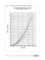
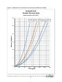
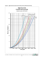
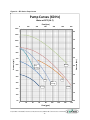
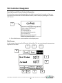
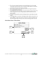
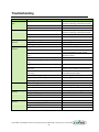
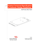
1
USER GUIDE UGH041-0613 www.conairgroup.com EP2 Series Portable Chillers Portable and Remote Condenser Chillers 4 to 43 tons Corporate Office: 724.584.5500 Instant Access 24/7 (Parts and Service): 800.458.1960 Parts and Service: 814.437.6861 Thank you for purchasing Conair equipment. This manual is addressed to operators and qualified technicians to ensure correct use of this Conair equipment. IMPORTANT: THIS MANUAL MUST BE READ BEFORE INSTALLATION. KEEP THIS MANUAL IN A PLACE ACCESSIBLE FOR ALL OPERATORS. It’s a good idea to record the model and serial number(s) of your equipment and the date you received it in the User Guide. Our service department uses this information, along with the manual number, to provide help for the specific equipment you installed. Please keep this user guide and all manuals, engineering prints and parts lists together for documentation of your equipment. Date: Manual Number: UGH041-0613__________ Serial Number(s): Model Number(s): Software Version: Disclaimer: The Conair Group shall not be liable for errors contained in this User Guide or for incidental, consequential damages in connection with the furnishing, performance or use of this information. Conair makes no warranty of any kind with regard to this information, including, but not limited to the implied warranties of merchantability and fitness for a particular purpose. © Copyright 2013, The Conair Group, All rights reserved. Corporate Office: 724.584.5500 Instant Access 24/7 (Parts and Service): 800.458.1960 Parts and Service: 814.437.6861 Table of Contents Foreword ................................................................................................................................. 1 Safety Guidelines ..................................................................................................................... 2 Installation ............................................................................................................................... 2 Receiving Inspection ..................................................................................................................... 2 Rigging, Handling, and Locating Equipment ................................................................................. 3 Foundation ................................................................................................................................... 3 Electrical Power ............................................................................................................................ 3 Condenser Water Lines (EP2W Models Only) .............................................................................. 4 Table 1 – Water Cooled Condenser Water Flow Rate Requirements ...................................... 5 Figure 1 – Condenser Water Pressure Drop Curves (EP2W‐05 thru EP2W‐15) ....................... 6 Figure 2 – Condenser Water Pressure Drop Curves (EP2W‐20 thru EP2W‐40) ....................... 7 Air‐Cooled Chillers Condenser Air ................................................................................................ 8 Chilled Water Lines ....................................................................................................................... 8 Figure 3 – Recommended Overhead Piping ............................................................................. 9 Table 2 – Chiller Flow Rate Limitations ................................................................................... 10 Figure 4 – Standard Flow Unit Coolant Pressure Drop Curve (EP2‐04 and EP2‐05) ............... 11 Figure 5 – High Flow Unit Coolant Pressure Drop Curve (EP2‐04 and EP2‐05) ...................... 12 Figure 6 – Standard Flow Unit Coolant Pressure Drop Curve (EP2‐08 thru EP2‐15) .............. 13 Figure 7 – High Flow Unit Coolant Pressure Drop Curve (EP2‐08 thru EP2‐15) ..................... 14 Figure 8 – Standard Flow Unit Coolant Pressure Drop Curve (EP2‐20 thru EP2‐40) .............. 15 Figure 9 – High Flow Unit Coolant Pressure Drop Curves (EP2‐20 thru EP2‐40) .................... 16 Figure 10 – EP2 Series Pump Curves ....................................................................................... 17 System Fluid Freeze Protection .................................................................................................. 18 Interconnecting Refrigerant Piping (EP2R Models Only) ........................................................... 18 Operating Principles ............................................................................................................... 19 Coolant Circuit ............................................................................................................................ 19 Refrigerant Circuit ...................................................................................................................... 19 Start‐Up ................................................................................................................................. 20 Table 3 ‐ Recommended Glycol Solutions .............................................................................. 21 Microprocesser Controller Operation .................................................................................... 23 Start Button ................................................................................................................................ 24 Stop Button ................................................................................................................................ 24 Alarm Silence / Alarm Reset Button ........................................................................................... 24 Compressor Running Hours Button ........................................................................................... 24 Pump Running Hours Button ..................................................................................................... 25 Pump Test Button ....................................................................................................................... 25 Display/Program Button ............................................................................................................. 25 Up Button ................................................................................................................................... 25 Down Button .............................................................................................................................. 26 Control Power On LED ................................................................................................................ 26 Corporate Office: 724.584.5500 Instant Access 24/7 (Parts and Service): 800.458.1960 Parts and Service: 814.437.6861 Autostart Signal LED ................................................................................................................... 26 Pump LED ................................................................................................................................... 26 Hot Gas Bypass LED .................................................................................................................... 26 Compressor #1 LED .................................................................................................................... 27 Compressor #2 LED .................................................................................................................... 27 Temperature Limit LED ............................................................................................................... 27 Electrical Phase Error LED .......................................................................................................... 28 Low Flow LED .............................................................................................................................. 28 Freezestat LED ............................................................................................................................ 28 Low Reservoir Level LED ............................................................................................................. 28 Compressor Recycle LED ............................................................................................................ 28 High Refrigerant Pressure LED ................................................................................................... 28 Low Refrigerant Pressure LED .................................................................................................... 29 Program Mode LED .................................................................................................................... 29 Setpoint Temperature Display ................................................................................................... 29 Actual Temperature Display ....................................................................................................... 29 Program Menu ........................................................................................................................... 29 Table 4 ‐ Controller Program Menu ........................................................................................ 31 Table 5 – Controller Control Fault Logic ................................................................................. 32 Table 6 – ModBus Option Parameters (Integer Values) ......................................................... 33 Table 7 – ModBus Option Parameters (Floating Point Values) .............................................. 34 PLC Controller Navigation ...................................................................................................... 36 Start‐Up Screen & Conair Contact Information ......................................................................... 36 Main Screen ................................................................................................................................ 36 Refrigeration Diagnostic Screen ................................................................................................. 38 Process Diagnostic Screen .......................................................................................................... 39 Active Alarms Screen / Alarm History ........................................................................................ 40 Output Status / Output Designation .......................................................................................... 42 Setup Screens ............................................................................................................................. 43 Compressor Setup................................................................................................................... 43 Temperature Alarm Settings .................................................................................................. 43 Freezestat Setup ..................................................................................................................... 43 Hot Gas Bypass PID ................................................................................................................. 43 Components .......................................................................................................................... 44 Chilled Water Return Temperature Sensor ................................................................................ 44 Chilled Water Supply Temperature Sensor ................................................................................ 44 Compressor ................................................................................................................................ 44 Compressor Electronic Motor Module ...................................................................................... 44 Condenser Remote Air‐Cooled (EP2R Models Only) .................................................................. 45 Condenser Integrated Air‐Cooled (EP2A Models Only) ............................................................. 45 Fan Cycling Controls (EP2A Models Only) .................................................................................. 45 Condenser Water‐Cooled (EP2W Models Only) ........................................................................ 45 Condenser Water Regulating Valve (EP2W Models Only) ......................................................... 45 Corporate Office: 724.584.5500 Instant Access 24/7 (Parts and Service): 800.458.1960 Parts and Service: 814.437.6861 Coolant Flow Switch ................................................................................................................... 46 Crankcase Heater ....................................................................................................................... 46 Evaporator .................................................................................................................................. 46 Hot Gas Bypass Valve ................................................................................................................. 46 High Refrigerant Pressure Switch ............................................................................................... 46 Low Refrigerant Pressure Switch ............................................................................................... 46 Human Machine Interface (HMI) ............................................................................................... 47 Pressure Relief Valve .................................................................................................................. 47 Receiver ...................................................................................................................................... 47 Refrigerant Filter/Drier ............................................................................................................... 47 Refrigerant Service Valve ........................................................................................................... 47 Refrigerant Sight Glass ............................................................................................................... 47 Y‐Strainer .................................................................................................................................... 48 Automatic Water Make‐Up (Optional) ....................................................................................... 48 Coolant Pump ............................................................................................................................. 48 Upgraded Pumps (Optional) ....................................................................................................... 48 Pressure Gauge........................................................................................................................... 48 Reservoir ..................................................................................................................................... 48 Preventive Maintenance ........................................................................................................ 49 Once a Week .............................................................................................................................. 49 Once a Month ............................................................................................................................. 50 Every Three Months ................................................................................................................... 50 Preventive Maintenance Checklist ......................................................................................... 51 Troubleshooting ..................................................................................................................... 52 Drawings ................................................................................................................................ 53 We’re Here to Help ................................................................................................................ 54 Equiptment Guarantee .......................................................................................................... 55 Corporate Office: 724.584.5500 Instant Access 24/7 (Parts and Service): 800.458.1960 Parts and Service: 814.437.6861 Foreword The intent of this manual is to serve as a guide for placing your portable chiller in service and operating and maintaining it properly. Improper installation can lead to poor equipment performance or severe equipment damage. Failure to follow the installation instructions may result in damage not covered by your warranty. It is extremely important that a qualified refrigeration installation contractor perform all installation line sizing and piping. Please supply these instructions to your authorized refrigeration contractor. This manual is for our standard product line with supplements as required to accommodate any special items provided for a specific application. The written information contained in this manual, as well as various drawings, are intended to be general in nature. The drawings included in this manual are typical only and may not represent the actual unit purchased. Actual drawings are included with the equipment for troubleshooting and servicing of the unit. Additional copies of drawings are available upon request. We strive to maintain an accurate record of all equipment during the course of its useful life. Every effort was made to standardize the design features of these chillers, the various options may make it necessary to rearrange some of the components; therefore, some of the general drawings in this manual may differ from your specific unit. Due to the ever‐changing nature of applicable codes, ordinances, and other local laws pertaining to the use and operation of this equipment we do not reference them in this manual. There is no substitute for common sense and good operating practices when placing any mechanical equipment into operation. We encourage all personnel to familiarize themselves with this manual's contents. Failure to do so may unnecessarily prolong equipment down time. The chilling equipment uses chemical refrigerants for heat transfer purposes. This chemical is sealed and tested in a pressurized system containing ASME coded vessels; however, a system failure will release it. Refrigerant gas can cause toxic fumes if exposed to fire. Place these units in a well‐ventilated area, especially if open flames are present. Failure to follow these instructions could result in a hazardous condition. The standard refrigerant used in these units is a hydro fluorocarbon (HFC) trade named R‐410A. We strongly recommend our customers implement a refrigerant management program including a survey of all equipment to document the type and quantity of refrigerant in each machine. We recommend all refrigeration service technicians be licensed and certified by an EPA approved organization. Follow good piping practices and the information in this manual to ensure a successful installation and operation of this equipment. We are not responsible for liabilities created by substandard piping methods and installation practices external to the chiller. We trust your equipment will have a long and useful life. If you should have any questions, please contact our Customer Service Department specifying the serial number and model number of the unit as indicated on the nameplate. Corporate Office: 724.584.5500 Instant Access 24/7 (Parts and Service): 800.458.1960 Parts and Service: 814.437.6861 1 Safety Guidelines Observe all safety precautions during installation, start‐up, and service of this equipment due to the presence of high voltage and refrigerant charge. Only qualified personnel should install, start‐up, and service this equipment. When working on this equipment, observe precautions in literature, and on tags, stickers, and labels located on the equipment. Wear work gloves and safety glasses. WARNING: This equipment contains hazardous voltages that can cause severe injury or death. Disconnect and lock out incoming power before installing or servicing the equipment. WARNING: This equipment contains refrigerant under pressure. Accidental release of refrigerant under pressure can cause personal injury and or property damage. Exercise care while working on or around this equipment. WARNING: Vent all refrigerant relief valves in accordance to ANSI/ASHRAE Standard 15, Safety Code for Mechanical Refrigeration. This equipment should be located within a well‐ventilated area. Inhalation of refrigerant can be hazardous to your health and the accumulation of refrigerant within an enclosed space can displace oxygen and cause suffocation. Installation Receiving Inspection Each chiller is skid mounted and boxed or crated prior to shipment. If the chiller has a remote air‐cooled condenser, the chiller and the condenser will ship skid mounted and will contain a holding charge of nitrogen. Before accepting delivery, check the overall equipment condition for any visible damage and document any damage that is evident on the delivery receipt. Shipping damage is the responsibility of the carrier. In order to expedite payment for damages, it is important to follow proper procedures and record keeping. Photographs of damaged equipment are excellent documentation for your records. Inspect for hidden damage after removing the packing. Refrigerant lines can be susceptible to damage in transit. Check for broken lines, oil leaks, damaged controls, or any other major component torn loose from its mounting point. Corporate Office: 724.584.5500 Instant Access 24/7 (Parts and Service): 800.458.1960 Parts and Service: 814.437.6861 2 Rigging, Handling, and Locating Equipment The units have either a formed sheet metal enclosure or a welded tube steel frame. Use proper rigging methods to prevent damage to components. Avoid impact loading caused by sudden jerking when lifting or lowering the chiller. Use pads on any abrasive surface contact areas. The frame supporting the unit is for positioning the unit with a crane or a forklift. Please refer to the drawings provided with the chiller for chiller rigging details. If the chiller has a remote air‐ cooled condenser, please refer to the Remote Condenser Installation Guidelines manual for further instructions on locating and rigging the remote condenser. This separate document has been prepared to assist refrigeration contractors with the installation and piping design for our remote condensers. Standard units are for indoor use and should not be installed or even stored in an outdoor location; however, some custom units are for outdoor installations. The unit can be stored in environments between ‐4°F (‐20°C) and 140°F (60°C) and is designed for operation in environments between 60°F (16°C) and 110°F (43°C). CAUTION: To prevent damage to the equipment caused by freezing, do not store or operate the unit in an ambient condition which may cause freezing without adequate freeze protection. Serviceability was a primary concern when designing your portable chiller. Do not compromise this feature by locating the chiller in an inaccessible area. Please allow a minimum of three feet (914.4 mm) around the perimeter of the chiller for required clearance around the chiller. Make sure that access to the electrical enclosure is unobstructed. For air‐cooled chillers, cooling performance may be limited if airflow in or out of the chiller is restricted. If it is necessary to store the chiller in an unheated area when not in use, drain all water from the unit or add an adequate amount of antifreeze to prevent freeze‐up of the unit. Foundation Provide a rigid mounting surface for the chiller of adequate strength to support the operating weight of the chiller. It is imperative to include the entire operating weight, including the completed piping and full operating weight of the refrigerant and water, in total operating weight support requirements. The chiller once mounted should be level within a 0.250 inch (6.350 mm) over the length and width of the unit. Electrical Power All wiring must comply with local codes and the National Electric Code. Minimum Circuit Ampacities (MCA) and other unit electrical data are on the unit serial tag. A specific electrical schematic is shipped with the unit. Measure each leg of the main power supply voltage at the main power source. Voltage must be within the voltage utilization range given on the chiller’s nameplate. If the measured voltage on any leg is not within the specified range, notify the supplier and correct before operating the unit. Voltage imbalance must not exceed two percent. Excessive voltage imbalance between the phases of a three‐phase system can cause motors to overheat and eventually fail. Corporate Office: 724.584.5500 Instant Access 24/7 (Parts and Service): 800.458.1960 Parts and Service: 814.437.6861 3 Voltage imbalance is determined using the following calculations: % Imbalance = (Vavg – Vx) x 100 / Vavg Vavg = (V1 + V2 + V3) / 3 Vx = phase with greatest difference from Vavg For example, if the three measured voltages were 198, 207, and 204 volts, the average would be: (198 + 207 + 204) / 3 = 203 The percentage of imbalance is then: (203 – 198) x 100 / 203 = 2.46 % This exceeds the maximum allowable voltage imbalance of 2%. The unit includes a terminal block for main power connection to the main power source. The main power source should be connected to the terminal block through an appropriate disconnect switch. A separate lug for grounding the unit is in the main control panel. Check the electrical phase sequence at installation and prior to start‐up. Operation of the compressor with incorrect electrical phase sequencing will result in mechanical damage to the compressors. Check the phasing with a phase sequence meter prior to applying power. The proper sequence should read ABC on the meter. If the meter reads CBA, open the main power disconnect and switch two line leads on the line power terminal blocks (or the unit mounted disconnect). All components are wired and phased correctly at the factory. Do not interchange any load leads that are from the unit contactors or the motor terminals. WARNING: It is imperative that L1‐L2‐L3 are connected in the A‐B‐C phase sequence to prevent equipment damage due to reverse rotation. CAUTION: The unit requires the main power to remain connected during off‐hours to energize the compressor’s crankcase heater. Disconnect main power only when servicing the chiller. The crankcase heater should remain on when the compressor is off to ensure liquid refrigerant does not accumulate in the compressor crankcase. WARNING: The control panel is constructed such that connecting the appropriate power source to the main terminal block energizes the entire electric circuitry of the chiller. A control transformer and power supply has been factory wired to step down the incoming power to the 115VAC and 24VDC control power. Electric power at the main disconnect must be shut off before opening access panels for repair or maintenance in order to prevent exposure to energized components. Ground the unit properly in compliance with local and national codes. Condenser Water Lines (EP2W Models Only) The performance of a condenser is dependent on maintaining the proper flow and temperature of water through the heat exchanger. Insufficient water flow or high condenser water supply temperature will result in the reduction of cooling capacity of the chiller. Extreme conditions will eventually result in the chiller shutting down due to high refrigerant pressure. If condenser Corporate Office: 724.584.5500 Instant Access 24/7 (Parts and Service): 800.458.1960 Parts and Service: 814.437.6861 4 fouling by contaminants in the condenser water stream occurs, performance is negatively affected. In order to reduce maintenance costs and chiller downtime, a water treatment program is highly recommended for the condenser cooling water. If condenser plugging occurs, contact our Customer Service Department for assistance in the proper procedure for cleaning out the condenser. Caution: The use of untreated or improperly treated water in a chiller can result in scaling, erosion, algae, or slime buildup. This can lead to poor system performance or premature failure. The standard cooling capacity assumes 85°F (29°C) condenser cooling water supply. Under normal operating conditions, there will be approximately 10°F (6°C) rise through the condenser resulting in 95°F (35°C) exiting water temperature from the condenser. To ensure proper water flow through the condenser, the condenser water pump must be able to supply the pressure drop given (see Figure 1 or Figure 2 on the following pages) when providing the required condenser water flow as shown in Table 1. While the design pressure loss is much lower than 25 PSI (1.75 Kg/cm2), we recommend the pumping system be sized for this loss to ensure there will be sufficient supply pressure to the condensers. To prevent damage to the condenser or regulating valve, the condenser water pressure should not exceed 150 PSIG (10.5 Kg/cm2). The condenser water regulating valve controls the condenser water flow. The chiller loading and condenser water inlet temperature determine the actual flow. The condenser water supply temperature range is from 70°F (21°C) to 90°F (32°C). Supply temperatures outside this range are not recommended and may lead to improper chiller operation. Table 1 – Water Cooled Condenser Water Flow Rate Requirements The water regulating Nominal Flow valve will modulate the Chiller Model gpm (lpm) psid (kPA) flow rate of condenser EP2W‐05 16.5 (62.5) 15.4 (106.1) water through the EP2W‐08 24.1 (91.2) 13.6 (93.7) condenser in order to EP2W‐10 35.8 (135.5) 29.4 (202.6) maintain the discharge EP2W‐15 48 (181.7) 23.2 (159.8) pressure setpoint. If the EP2W‐20 64.9 (245.7) 11.1 (76.5) EP2W‐25 81.7 (309.3) 9.5 (65.5) discharge pressure is EP2W‐30 96.4 (365) 18.2 (125.4) above the setpoint, the EP2W‐35 111.6 (422.5) 27.3 (188.1) water‐regulating valve EP2W‐40 124.3 (470.6) 30.6 (210.8) will open to increase the water flow attempting to provide more cooling. The condenser water flow can exceed nominal flow rates during these conditions and reduce the available water flow through other processes if sharing the same pump. Warning: If the condenser water pump is feeding other sources in addition to the chiller, it is highly recommended to install an appropriate balance valve in line with the chiller in order to limit the maximum flow through the chiller. Corporate Office: 724.584.5500 Instant Access 24/7 (Parts and Service): 800.458.1960 Parts and Service: 814.437.6861 5 Figure 1 – Condenser Water Pressure Drop Curves (EP2W-05 thru EP2W-15) Condenser Water Pressure Drop Base on water at 85°F (29.4°C) 45.0 EP2W‐10 40.0 EP2W‐15 35.0 Pressure Drop (psi) 30.0 EP2W‐05 25.0 EP2W‐08 20.0 15.0 10.0 5.0 0.0 0.0 10.0 20.0 30.0 40.0 50.0 60.0 70.0 Flow (gpm) Corporate Office: 724.584.5500 Instant Access 24/7 (Parts and Service): 800.458.1960 Parts and Service: 814.437.6861 6 Figure 2 – Condenser Water Pressure Drop Curves (EP2W-20 thru EP2W-40) Condenser Water Pressure Drop Base on water at 85°F (29.4°C) 50.0 EP2W‐40 45.0 EP2W‐35 40.0 Pressure Drop (psi) 35.0 30.0 EP2W‐30 25.0 20.0 EP2W‐20 EP2W‐25 15.0 10.0 5.0 0.0 0.0 25.0 50.0 75.0 100.0 125.0 150.0 175.0 Flow (gpm) Corporate Office: 724.584.5500 Instant Access 24/7 (Parts and Service): 800.458.1960 Parts and Service: 814.437.6861 7 Air‐Cooled Chillers Condenser Air This section only applies to air‐cooled chillers. In order to accommodate the air‐cooled condenser, the chiller must be located in a well‐ventilated area. A minimum of three feet (914.4 mm) of clearance is required at both the condenser air inlet and condenser air discharge. Improper clearance or poor ventilation will reduce the cooling capacity of the chiller and may cause high refrigerant pressure problems. The condenser air inlet temperature must be above 60°F (15°C) in order to avoid possible low refrigerant pressure safety trips during start‐up. The performance of an air‐cooled condenser is dependent upon maintaining the proper flow of air across the heat exchanger surface. If the airflow is restricted at either the intake or discharge, the cooling capacity of the chiller is reduced. Reduced airflow may also result in high refrigerant pressure problems that may cause the chiller to shut down. Airflow can also be reduced if the condenser air inlet filters become clogged with dirt. Cleaning these filters should be part of the routine maintenance program for this chiller. The frequency of required cleaning depends on the environment in which the chiller operates. The standard rated cooling capacity of this chiller is based upon 95°F (35°C) ambient air temperature. If the air temperature entering the condenser is above 95°F (35°C), the capacity will be reduced approximately 1% per 1°F (0.5°C). Entering air temperature above 110°F (43°C) may result in high refrigerant pressure problems that would shut the unit down. For this reason, it is very important that the chiller be located where the warm discharge air does not circulate back into the condenser inlet. These chillers are for indoor usage with normal indoor ambient air temperature entering the condenser. Air temperatures below 60°F (15°C) entering the condenser may result in low refrigerant pressure cold start‐up problems. Chilled Water Lines To prevent unwanted condensation, insulate all chilled water piping. If water vapor condenses on the piping, the state change of the water from gas to liquid will result in a substantial heat load that becomes an additional burden for the chiller. Standard portable chillers provide 50°F (10°C) coolant to the process. Under normal operating conditions there will be a 10°F (6°C) rise through the process resulting in 60°F (16°C) return coolant temperature to the chiller. The importance of properly sized piping between the chiller and process cannot be overemphasized. See the ASHRAE Handbook or other suitable design guide for proper pipe sizing. In general, run full size piping out to the process and then reduce the pipe size to match the connections on the process equipment. Poorly designed piping is one of the most common causes of unsatisfactory chiller performance. Avoid unnecessarily long lengths of hoses or quick disconnect fittings that offer high resistance to water flow. When manifolds are required for water distribution, install them as close to the use point as possible. Provide flow balancing valves at each chilled water use point to assure adequate water distribution in the entire system. The connection labeled “Chilled Water Supply” delivers fluid to the process and the connection labeled “Chilled Water Return” receives water back from the process. Typically, Corporate Office: 724.584.5500 Instant Access 24/7 (Parts and Service): 800.458.1960 Parts and Service: 814.437.6861 8 when piping is overhead with a total run length over 90 feet (27 M) there should be a valve in the supply line and an inverted P trap with a vacuum break valve installed as shown in Figure 3. Figure 3 – Recommended Overhead Piping Figures 4 through 9 (on the following 12 inches above highest pages) provide the pressure drop point in piping system through the evaporator and chilled water piping associated with the 1/2 inch vacum break valve chiller. Use this information for assistance when sizing a chilled water pump. Nominal chilled water flow rates are provided in Table 2 and are based Check valve on a 10°F (18°C) range across the evaporator at 50°F (10°C) LWT and 85°F NOTE: (29.4°C) entering condenser water. If piping is above chiller and exceeds 90 feet in total length, install an inverted P-trap and vacuum break valve in return line and add a check valve to the Pump curves for typical optional pumps supply line. with 60 Hz power are in shown in Figure 10 – EP2 Series Pump Curves. The minimum flow rates are required to prevent fouling and to ensure the chiller stays within normal refrigerant operating conditions. If the process flow requirement is lower than the minimum flow limitation shown in Table 2 (on the next page), multiple smaller chillers may be used. Another alternative is to use a primary pumping loop designed for lower flow at a higher temperature rise through the process and a secondary pumping loop designed for a higher flow and lower temperature drop through the chiller. If a secondary pumping loop is used, maintain the mixed temperature of coolant entering the evaporator at a minimum of at least 5°F (2.8°C) above the setpoint of the chiller. The maximum flow limitation shown in Table 2 is the theoretical limits of the chiller based upon a 5°F (2.8°C) drop across the chiller; however, these flows result in impractical pressure drops through the chiller and are therefore not likely for a system design. If the process flow requirement is higher than the maximum flow limitation, a bypass around the chiller may be used. Another alternative is to use a primary pumping loop designed for higher flow and lower temperature rise through the process and a secondary pumping loop designed for lower flow and higher temperature drop through the chiller. If a secondary pumping loop is used, maintain the mixed temperature of coolant entering the chiller at a minimum of at least 5°F (2.8°C) above the setpoint of the chiller. The use of varying chiller flows is sometimes necessary; however, it is highly recommended to use a dedicated evaporator circulation pump to provide increased system stability. The controls of the chiller are very adaptable and are capable of adjusting to variations in the flow of water through the system and will load and unload compressor(s) as needed to maintain tight control of the leaving water temperature of the system. If the chiller flow is varied, the minimum fluid loop volume must be in excess of 3 gallons of coolant per ton of cooling (3.2 L per kW) and the Corporate Office: 724.584.5500 Instant Access 24/7 (Parts and Service): 800.458.1960 Parts and Service: 814.437.6861 9 flow rate must change at a rate of no greater than 10% per minute in order to maintain an acceptable level of temperature control. This is a practical amount of water which typically buffers fluctuations in the process enough that the chiller will generally see fairly gradual rates of change in the inlet water temperature and will be able to accurately load or unload the compressor(s) which in turn will allow for very consistent and stable supply temperatures to the process. Use a system volume of 6 to 10 gallons of coolant per ton (6.4 to 10.8 L per kW) if the flow rate changes more rapidly than 10% per minute. If the chiller sees a net rate of change greater than 10% per minute it may result in temporary supply temperature fluctuations greater than 1°F (0.5°C). Table 2 – Chiller Flow Rate Limitations Chiller Model EP2A‐04 EP2R‐04 EP2A‐05 EP2R‐05 EP2A‐08 EP2R‐08 EP2A‐10 EP2R‐10 EP2A‐13 EP2A‐15 EP2R‐15 EP2A‐20 EP2R‐20 EP2A‐25 EP2R‐25 EP2A‐30 EP2R‐30 EP2A‐35 EP2R‐35 EP2A‐40 EP2R‐40 EP2W‐05 EP2W‐08 EP2W‐10 EP2W‐15 EP2W‐20 EP2W‐25 EP2W‐30 EP2W‐35 EP2W‐40 Minimum Flow gpm (lpm) psi (kPA) 4.9 (18.5) 1.5 (10.2) 4.9 (18.5) 1.5 (10.2) 5.9 (22.1) 1.9 (13) 5.9 (22.1) 1.9 (13) 8.6 (32.4) 1.6 (11.2) 8.6 (32.4) 1.6 (11.2) 12.8 (48.4) 2.7 (18.3) 12.8 (48.4) 2.7 (18.3) 14.7 (55.6) 2.4 (16.5) 17.3 (65.5) 2.1 (14.7) 17.3 (65.5) 2.1 (14.7) 23 (87.1) 2.5 (17) 23 (87.1) 2.5 (17) 29.2 (110.4) 1.9 (13.3) 29.2 (110.4) 1.9 (13.3) 34.6 (130.8) 2.2 (15.4) 34.6 (130.8) 2.2 (15.4) 40 (151.2) 1.9 (13) 40 (151.2) 1.9 (13) 45.4 (171.7) 2 (14.1) 45.4 (171.7) 2 (14.1) 6.4 (24) 2.2 (15.3) 9.2 (34.8) 1.9 (12.8) 14 (53) 3.2 (21.9) 18.7 (70.8) 2.5 (17.2) 25 (94.6) 2.9 (20.1) 31.5 (119.2) 2.2 (15.5) 37.2 (140.8) 2.6 (17.8) 42.7 (161.6) 2.2 (14.9) 47.6 (180.2) 2.2 (15.5) Nominal Flow gpm (lpm) psi (kPA) 9.7 (36.7) 5.8 (40) 9.7 (36.7) 5.8 (40) 11 (41.6) 6.6 (45.5) 11 (41.6) 6.6 (45.5) 16.8 (63.6) 6.2 (42.7) 16.8 (63.6) 6.2 (42.7) 24 (90.8) 9.3 (64.1) 24 (90.8) 9.3 (64.1) 26.7 (101.1) 7.9 (54.5) 32.1 (121.5) 7.4 (51) 32.1 (121.5) 7.4 (51) 43.4 (164.3) 8.8 (60.7) 43.4 (164.3) 8.8 (60.7) 54.5 (206.3) 6.7 (46.2) 54.5 (206.3) 6.7 (46.2) 64.3 (243.4) 7.7 (53.1) 64.3 (243.4) 7.7 (53.1) 94.5 (357.7) 10.6 (73.1) 94.5 (357.7) 10.6 (73.1) 104.8 (396.7) 10.9 (75.2) 104.8 (396.7) 10.9 (75.2) 12.7 (48.1) 8.7 (60) 18.5 (70) 7.5 (51.7) 27.6 (104.5) 12.3 (84.8) 36.9 (139.7) 9.7 (66.9) 50.3 (190.4) 11.8 (81.4) 62.8 (237.7) 8.9 (61.4) 74.3 (281.3) 10.3 (71) 86.3 (326.7) 8.8 (60.7) 95.8 (362.6) 9.1 (62.7) Maximum Flow gpm (lpm) psi (kPA) 19.6 (74.2) 23.8 (163.8) 19.6 (74.2) 23.8 (163.8) 23.4 (88.6) 29.7 (204.4) 23.4 (88.6) 29.7 (204.4) 34.2 (129.4) 25.7 (176.9) 34.2 (129.4) 25.7 (176.9) 51.2 (193.8) 42.4 (292.4) 51.2 (193.8) 42.4 (292.4) 58.8 (222.6) 38.4 (264.4) 69.2 (261.9) 34.2 (235.9) 69.2 (261.9) 17.3 (65.5) 92 (348.2) 39.5 (272.5) 92 (348.2) 23 (87.1) 116.6 (441.5) 30.8 (212) 116.6 (441.5) 30.8 (212) 138.2 (523.2) 35.7 (245.7) 138.2 (523.2) 35.7 (245.7) 159.8 (605) 30.2 (208.2) 159.8 (605) 30.2 (208.2) 181.4 (686.8) 32.6 (225) 181.4 (686.8) 32.6 (225) 25.4 (96.1) 35 (240.8) 36.8 (139.3) 29.7 (204.8) 56 (212) 50.8 (349.8) 74.8 (283.1) 40 (275.6) 100 (378.5) 46.7 (321.9) 126 (476.9) 35.9 (247.5) 148.8 (563.2) 41.3 (284.8) 170.8 (646.5) 34.5 (237.9) 190.4 (720.7) 36 (247.8) Corporate Office: 724.584.5500 Instant Access 24/7 (Parts and Service): 800.458.1960 Parts and Service: 814.437.6861 10 Figure 4 – Standard Flow Unit Coolant Pressure Drop Curve (EP2-04 and EP2-05) Standard Unit Coolant Pressure Drop Based on water at 50°F (10°C) 30 EP2‐05 EP2‐04 25 Pressure Drop (psi) 20 15 10 5 0 0 5 10 15 20 25 Flow (gpm) Corporate Office: 724.584.5500 Instant Access 24/7 (Parts and Service): 800.458.1960 Parts and Service: 814.437.6861 11 Figure 5 – High Flow Unit Coolant Pressure Drop Curve (EP2-04 and EP2-05) High Flow Unit Coolant Pressure Drop Base on water at 50°F (10°C) 30 EP2‐04 & EP2‐05 25 Pressure Drop (psi) 20 15 10 5 0 0 5 10 15 20 25 30 35 40 Flow (gpm) Corporate Office: 724.584.5500 Instant Access 24/7 (Parts and Service): 800.458.1960 Parts and Service: 814.437.6861 12 Figure 6 – Standard Flow Unit Coolant Pressure Drop Curve (EP2-08 thru EP2-15) Standard Unit Coolant Pressure Drop Based on water at 50°F (10°C) 30 EP2‐08 EP2‐10 EP2‐13 EP2‐15 25 Pressure Drop (psi) 20 15 10 5 0 0 10 20 30 40 50 60 70 Flow (gpm) Corporate Office: 724.584.5500 Instant Access 24/7 (Parts and Service): 800.458.1960 Parts and Service: 814.437.6861 13 Figure 7 – High Flow Unit Coolant Pressure Drop Curve (EP2-08 thru EP2-15) High Flow Unit Coolant Pressure Drop Based on water at 50°F (10°C) 30 EP2‐08 EP2‐13 EP2‐10 EP2‐15 25 Pressure Drop (psi) 20 15 10 5 0 0 10 20 30 40 50 60 70 80 90 100 110 120 Flow (gpm) Corporate Office: 724.584.5500 Instant Access 24/7 (Parts and Service): 800.458.1960 Parts and Service: 814.437.6861 14 Figure 8 – Standard Flow Unit Coolant Pressure Drop Curve (EP2-20 thru EP2-40) Standard Unit Coolant Pressure Drop Based on water at 50°F (10°C) 30 EP2‐20 EP2‐25 EP2‐30 EP2‐35 125 150 EP2‐40 25 Pressure Drop (psi) 20 15 10 5 0 0 25 50 75 100 175 Flow (gpm) Corporate Office: 724.584.5500 Instant Access 24/7 (Parts and Service): 800.458.1960 Parts and Service: 814.437.6861 15 Figure 9 – High Flow Unit Coolant Pressure Drop Curves (EP2-20 thru EP2-40) High Flow Unit Coolant Pressure Drop Based on water at 50°F (10°C) 30 EP2‐35 EP2‐30 EP2‐20 EP2‐25 EP2‐40 25 Pressure Drop (psi) 20 15 10 5 0 0 25 50 75 100 125 150 175 200 Flow (gpm) Corporate Office: 724.584.5500 Instant Access 24/7 (Parts and Service): 800.458.1960 Parts and Service: 814.437.6861 16 Figure 10 – EP2 Series Pump Curves Pump Curves (60 Hz) Water at 50°F (10 C) Flow (lpm) 0 100 200 300 400 500 600 120.0 8.0 110.0 7.0 100.0 90.0 6.0 80.0 Pressure (psi) 60.0 10 hp 3 hp 2‐stage 4.0 Pressure (bar) 5.0 70.0 50.0 3.0 40.0 5 hp 3 hp 5 hp 2‐stage 30.0 2.0 1½ hp 7½ hp 20.0 1.0 10.0 0.0 0.0 0 20 40 60 80 100 120 140 160 Flow (gpm) Corporate Office: 724.584.5500 Instant Access 24/7 (Parts and Service): 800.458.1960 Parts and Service: 814.437.6861 17 System Fluid Freeze Protection For applications where system fluid will be exposed to ambient conditions of 32°F (0°C) or colder and/or the setpoint of the system will be below 45°F (7.2°C), antifreeze must be added to the system fluid to protect the chiller and system piping from potential damage. The amount of antifreeze will vary depending on the actual desired operating conditions and should be enough to provide freeze protection to temperatures 15°F (8.3°C) colder than the coldest temperature anticipated. Use only antifreeze solutions designed for heat exchanger duty. Do not use automotive antifreeze due to the potential for fouling that can occur once its relatively short‐lived inhibitors break down. Interconnecting Refrigerant Piping (EP2R Models Only) The chiller is shipped with a nitrogen holding charge and has a full charge of oil, excluding the additional charge for field piping. Proper evacuation is required prior to charging with refrigerant. The chiller is for use only with the air‐cooled condenser provided with the unit. The following section covers the required piping between the chiller and the provided air‐cooled condenser. Caps are located on the discharge and liquid lines. These line sizes do not necessarily reflect the actual line sizes required for the piping between the chiller and the air‐cooled condenser. The installing contractor need only provide the interconnecting piping between the chiller and the air‐cooled condenser. Refrigerant piping size and piping design has a significant effect on system performance and reliability. For specific pipe sizing and configuration, refer to the EP2R Series Chiller Remote Air‐ Cooled Condenser Installation Guidelines Manual. All piping should conform to the applicable local and state codes. Use refrigerant grade copper tubing only and isolate the refrigeration lines from building structures to prevent transfer of vibration. Do not use a saw to remove end caps. This might allow copper chips to contaminate the system. Use a tube cutter or heat to remove the caps. When sweating copper joints it is important to flow dry nitrogen through the system. This prevents scale formation. Do not use soft solders. For copper‐to‐copper joints use a phos‐copper solder with 6% to 8% silver content. Use a high silver content brazing rod for copper‐to‐brass or copper‐to‐steel joints. Only use oxy‐acetylene brazing. Corporate Office: 724.584.5500 Instant Access 24/7 (Parts and Service): 800.458.1960 Parts and Service: 814.437.6861 18 Operating Principles Coolant Circuit The coolant pump, external to the chiller, circulates coolant through the process piping and then back to the chiller. Upon entering the chiller, the coolant will pass through a Y‐Strainer that filters the process fluid before entering the evaporator. Heat transferred from the coolant to the refrigerant occurs in the evaporator. Varying the amount of heat transferred in the evaporator determines the loading of the compressor, which maintains the temperature setpoint of the coolant delivered to the process. A “Process Return” temperature sensor senses the temperature of the coolant as it enters the evaporator. After leaving the evaporator, the coolant passes by a flow switch and the “Process Supply” temperature sensor. The sensor senses the temperature of the coolant delivered to process and communicates this temperature to the PLC controller. This sensor is the control sensor for the PLC control system. Refrigerant Circuit The heat transferred in the evaporator from the coolant to the refrigerant changes the state of the refrigerant from a liquid to a gas. This refrigerant gas then moves from the evaporator to the compressor. The compressor is the heart of the refrigeration circuit. Cool, low‐pressure gas enters the compressor and hot, high‐pressure gas exits the compressor. Since the compressor is not 100% efficient, some extra heat gain occurs as the refrigerant is compressed. The hot, high‐pressure gas exiting the compressor goes to the condenser. In water‐cooled condenser units (EP2W models), the heat is transferred from the refrigerant flow around the tubes to the water that is flowing through the tubes. In air‐cooled condenser units (EP2A & EP2R models), the heat is transferred from the refrigerant in the finned tubes to the air that is flowing across the finned tubes. As the heat transfer occurs, the refrigerant changes from a gas to a liquid. The condenser removes the heat from the process load and the heat that is added by the compressor. After leaving the condenser, the liquid refrigerant passes through the filter dryer and sight glass. The filter dryer filters out any particles and/or moisture from the refrigerant. Use the sight glass to monitor the stream of liquid refrigerant. The liquid refrigerant then passes through the thermostatic expansion valve, which meters the flow into the evaporator where the process begins again. Capacity control is achieved by redirecting some of the hot gas from the compressor outlet away from the condenser. This gas is metered through an electronically controlled, stepper motor driven Hot Gas Bypass Valve. The hot gas is injected into the evaporator inlet, reducing the chiller’s cooling capacity during light loading. The Hot Gas Bypass Valve is opened by the PLC when the supply water temperature is below the Temperature Setpoint. Corporate Office: 724.584.5500 Instant Access 24/7 (Parts and Service): 800.458.1960 Parts and Service: 814.437.6861 19 Start‐Up Every unit is factory set to deliver chilled water in accordance with the standard operating specifications for that particular chiller. Due to variables involved with different applications and different installations, minor adjustments may be required during the initial start‐up to ensure proper operation. The following startup procedure should be followed in sequence. If trouble is encountered during start‐up, the fault can usually be traced to one of the control or safety devices. This outline can be used as a checklist for the initial start‐up and for subsequent start‐ups if the chiller is taken out of service for a prolonged period of time. 1. Assure the main power source is connected properly, that it matches the voltage shown on the nameplate of the unit, and that it is within the voltage utilization range given in the Electrical Power Section of this manual. Electrical phase sequence must be checked at installation and prior to start‐up. Operation of the compressor with incorrect electrical phase sequencing will result in mechanical damage to the compressors. The phasing must be checked with a phase sequence meter prior to applying power. The proper sequence should read “ABC” on the meter. If the meter reads “CBA”, open the main power disconnect and switch two line leads on the line power terminal blocks (or the unit mounted disconnect). All components requiring electric power are wired in‐phase at the factory. Do not interchange any load leads that are from the unit contactors or the motor terminals. Once proper power connection and grounding have been confirmed, turn the main power on. WARNING: It is imperative that L1‐L2‐L3 are connected in the A‐B‐C phase sequence to prevent equipment damage due to reverse rotation. Note: The main power must be on for 24 hours prior to starting the compressor to allow the crankcase heater to sufficiently vaporize any liquid refrigerant that may be present in the compressor. 2. Check to make sure that all process chilled water piping connections are secure. Open the cabinet and fill the chilled water reservoir with the proper water or water/glycol solution. Use glycol with a corrosion inhibitor only. See Table 3 (on the next page) for recommended glycol solutions. 25% glycol is recommended even if running at temperatures higher than 25°F to help protect the evaporator from potential freezing. 3. (EP2W Models Only) Check the condenser water lines to make sure all connections are secure. Make sure sufficient condenser water flow and pressure are available, the condenser water supply is turned on, and all shut‐off valves are opened 4. (EP2R Models Only) Check the refrigerant lines to make sure all connections are secure and that a proper evacuation of the chiller, the field piping, and the remote condenser has occured. Corporate Office: 724.584.5500 Instant Access 24/7 (Parts and Service): 800.458.1960 Parts and Service: 814.437.6861 20 5. Charge the chiller with refrigerant. For EP2R Table 3 - Recommended Glycol Solutions chillers, please refer to the EP2R Series Chiller Remote Air‐Cooled Condenser Installation Chilled Water Percent Glycol Temperature By Volume Guidelines Manual to determine the required 50°F (10°C) Not required refrigerant charge. EP2A and EP2W chillers 45°F (7.2°C) 5 % come factory charged and should require no 40°F (4.4°C) 10 % additional refrigerant. 35°F (1.7°C) 15 % 30°F (‐1.1°C) 20 % 6. (EP2R Models Only) Check the remote 25°F (‐3.9°C) 25 % condenser main power and control wiring to 20°F (‐6.7°C) 30 % ensure all connections are secure. 15°F (‐9.4°C) 35 % 10°F (‐12.2°C) 35 % 7. Verify that all refrigerant valves are open. 5°F (‐15°C) 40 % 0°F (‐17.8°C) 40 % 8. Make sure the Freezestat is set appropriately for the operating conditions of the chiller. The Freezestat setting is in a password protected menu of the chiller controller. Refer to the Controller Operation Section for instruction on how to access this menu, It should be set at 10°F (5°C) below the minimum chilled water temperature setting that the chiller will be operating. Reference Table 3 to be sure the coolant solution has sufficient freeze protection (glycol) to handle at least 5°F (2.8°C) below the Freezestat setting. All chillers are shipped from the factory with the Freezestat set at 38°F (3°C). This is done to protect against a possible freeze‐up if no glycol has been added to the coolant. Once the proper glycol solution has been added, the Freezestat can be adjusted to the appropriate setting. Note: The manufacturer’s warranty does not cover the evaporator from freezing. It is vital that the Freezestat is set properly. 9. Turn on the control power by turning the control power switch to "On". The panel displays should now be illuminated. 10. Due to extreme ambient temperatures that the unit may be exposed to during shipment, the High Refrigerant Pressure switch may have tripped. If this is the case, disconnect the main power and reset the High Refrigerant Pressure by depressing the manual reset button located on the switch. Reconnect the main power and turn the control power on by pressing the Power button. Clear the alarm condition by pressing the Alarm Reset button. 11. Establish flow through the evaporator. Standard units are provided with an internal pump that can be energized by pressing the Start button. If the unit has been customized and does not have an internal pump, the external pump should be energized to establish flow through the evaporator. Note: The compressor will not start as long as the flow switch is open. A positive flow must be established through the evaporator before the compressor can operate. Corporate Office: 724.584.5500 Instant Access 24/7 (Parts and Service): 800.458.1960 Parts and Service: 814.437.6861 21 12. Set water flow through the evaporator as indicated in Table 1 (on page 5) using a discharge throttling valve or flow control valve (by others). The valve should be the same size as the To Process connection of the chiller. A significant increase in flow beyond the recommended rate may damage the evaporator and create excessive pressure drops that influence the overall efficiency of the system. 13. Set the desired leaving water temperature on the control panel. The chiller should now be controlling to the selected temperature. Please note that if there is insufficient load the compressor may cycle on and off causing swings in temperature. WARNING: Under no circumstance should the High Refrigerant Pressure or the Low Compressor Pressure switch be deactivated. Failure to heed this warning can cause serious compressor damage, severe personal injury or death. 14. Regulation of the chiller temperature is based on supply water temperature. Unless otherwise specified, it is factory set to deliver coolant at 50°F (10°C). Adjust to the desired operating temperature. Resetting the temperature will change the operating conditions of the chiller. Any lower readjustment of the controller must be done only after referencing Table 3 (on the previous page) to ensure that the coolant has adequate antifreeze protection. 15. Operate the system for approximately 30 minutes. Check the liquid line sight glass. The refrigerant flow past the sight glass should be clear. Bubbles in the refrigerant indicate either low refrigerant charge or excessive pressure drop in the liquid line. A shortage of refrigerant is indicated if operating pressures are low and subcooling is low. Normal subcooling ranges are from 10°F (5.5°C) to 20°F (11°C). If subcooling is not within this range, check the superheat and adjust if required. The superheat should be approximately 10°F (5.5°C). Since the unit is factory charged, adding or removing refrigerant charge should not be necessary. If the operating pressures, sight glass, superheat, and subcooling readings indicate a refrigerant shortage, charge refrigerant as required. With the unit running, add refrigerant vapor by connecting the charging line to the suction service valve and charging through the backseat port until operating conditions become normal. CAUTION: A clear sight glass alone does not mean that the system is properly charged. Also check system superheat, subcooling, and unit operating pressures. If both suction and discharge pressures are low but subcooling is normal, a problem other than refrigerant shortage exists. Do not add refrigerant, as this may result in overcharging the circuit. Once proper flow and temperature are achieved, press the Stop button. The unit is now ready to be placed into service. Corporate Office: 724.584.5500 Instant Access 24/7 (Parts and Service): 800.458.1960 Parts and Service: 814.437.6861 22 Microprocesser Controller Operation The chiller includes a microprocessor controller to perform all control functions directly from the front panel. When Control Power is applied, the controller initiates a diagnostic test of each indicating light and display segment which momentary lights them sequentially. As part of this initial diagnostic test, the program revision level display in the temperature display for a moment. After the initial diagnostic sequence is completed, the controller is ready for operation. Corporate Office: 724.584.5500 Instant Access 24/7 (Parts and Service): 800.458.1960 Parts and Service: 814.437.6861 23 Start Button Depressing the Start button will start the pump and enable the compressor. The compressor (and condenser fans if the chiller is air cooled) will start only if the microprocessor is calling for cooling because the actual To Process temperature is higher than the Setpoint temperature. If the Autostart feature is enabled, the Autostart signal will have precedence over the Start Button. See the Program Menu section for instructions on how to enable or disable the Autostart feature. The Start button also performs an “Enter” function while in the programming menu. Stop Button Depressing the Stop button will shut off the compressor, pump, condenser fans (if the chiller is air cooled), and clear all fault signals. If the Autostart feature is enabled and there is an Autostart signal present, the Stop button will not stop the chiller. See the Program Menu section for instructions on how to enable or disable the Autostart feature. This button also performs a “Cancel” function while in the programming menu. Alarm Silence / Alarm Reset Button When an alarm condition is present, the alarm LED above the Alarm Silence/Reset button will be on and red. The first Alarm Silence/Reset button press will silence the alarm horn (optional), open the remote alarm contact (optional), and the LED toggles from red to yellow. The alarm horn and/or remote alarm contact remain disabled until a subsequent alarm occurs. A second press of the Alarm Silence/Reset button resets the state from Alarm to Normal Operation. The High Refrigerant Pressure and Pump Overload require a mechanical safety to be manually reset before the control board can be reset. If the fault is still present the unit will immediately go into a new alarm state. Compressor Running Hours Button Press and hold the Compressor Running Hours Button to display the amount of time that each compressor in the system has been enabled. The Setpoint window will show which compressor’s usage is being displayed (for units with two compressors). The running hours will be shown in the process display window. Display of running hours is in units of hundreds so a display value of 10 would mean 1,000 hours. The running hours will be displayed for as long as the button is held. For units with two compressors, the display will toggle between the two compressors every three seconds. The hours will be displayed for as long as the button is held. Control is not disturbed while the hours are being displayed. Corporate Office: 724.584.5500 Instant Access 24/7 (Parts and Service): 800.458.1960 Parts and Service: 814.437.6861 24 Pump Running Hours Button Press and hold the Pump Running Hours Button to display the amount of time that the pump has been enabled. The running hours will be shown in the process display window. Display of running hours is in units of hundreds so a display value of 10 would mean 1,000 hours. The running hours will be displayed for as long as the button is held. The hours will be displayed for as long as the button is held. Control is not disturbed while the hours are being displayed. Pump Test Button While the chiller is stopped, this button may be used to briefly engage the pump to test its operation. The pump will not run if there are any active alarms. The pump may be shut down by either pressing the Stop button or pressing the Pump Test button a second time. If no action is taken, the pump will shut down after one minute of operation. Display/Program Button The Display/Program button will change the temperature displayed in the Process screen from Supply to Return. When the display is set to supply temperature, there will be an orange indicating light in the lower right corner of the Process temperature display. When the display is set to return temperature, there will be no orange indicating light in the lower right corner of the Process temperature display. To toggle the process temperature display from supply to return temperature, press and release the Display/Program button. The display will return to the default Supply temperature automatically after 5 seconds without a button press. In addition to switching between the supply and return process temperature displays, the Display/Program button will initiate and navigate through the program menu. See the Program Menu section for more detail. Up Button The Up Arrow button raises the setpoint temperature. Pressing the Up Arrow and releasing it increases the setpoint temperature by one degree. Pressing the Up Arrow button and holding it increases the setpoint temperature until reaching the maximum allowable setpoint temperature. In addition to adjusting the setpoint temperature, the Up Arrow button adjusts various alarms and setpoint values when the unit is the programming mode. Corporate Office: 724.584.5500 Instant Access 24/7 (Parts and Service): 800.458.1960 Parts and Service: 814.437.6861 25 Down Button The Down Arrow button decreases the setpoint temperature. Pressing the Down Arrow and releasing it decreases the setpoint temperature by one degree. Pressing the Down Arrow button and holding it decreases the setpoint temperature until reaching the minimum allowable setpoint temperature. In addition to adjusting the setpoint temperature, the Down Arrow button adjusts various alarms and setpoint values when the unit is in the programming mode. Control Power On LED The Control Power light is on and green when the Control Power Switch is in the ON position and 24VDC control voltage is present. Autostart Signal LED The Autostart Signal light is on and yellow when the Autostart function is enabled and no Autostart signal is present. It is on and green when the Autostart function is enabled and the signal is present. This feature allows the unit to be turned on and off by a remote contact closure. Switching the contacts from open to close simulates pressing the Start button on the control panel. Switching the contacts from closed to open simulates pressing the Stop button. From the factory, the Autostart feature is disabled. See the Program Menu section for instructions on how to enable or disable the Autostart feature. Warning: Do not introduce any external voltage to these contacts, as this will result in damage to the microprocessor. Pump LED The Pump LED is solid green while in normal running operation. It will flash red if the overload safety trips. Hot Gas Bypass LED The Hot Gas Bypass LED will pulse or be illuminated solidly when the chiller is operating at partial load. Under partial load, the hot gas bypass valve is opened in order for the chiller to maintain a constant To Process temperature. The hot gas bypass valve opens to a variable percentage. The LED indicates an approximate opening percentage by pulsing for varying amounts of time. If the LED is illuminated for 5 seconds, that means that the valve is open 50%, while if it is opened for 10 seconds, it is open 100%. The longer that this LED stays on, the more unused excess capacity is available from the chiller. If the Partial Load LED stays off, the chiller Corporate Office: 724.584.5500 Instant Access 24/7 (Parts and Service): 800.458.1960 Parts and Service: 814.437.6861 26 is fully loaded by the heat from the process. If the Partial Load LED stays on, the chiller has a very small load on it from the process. If this low load condition persists, the To Process temperature may begin to drop below the Setpoint temperature, eventually cycling off compressor(s). Compressor 1 LED The Compressor 1 LED is solid green while Compressor #1 is running. It will flash red if a compressor overload condition exists (only chillers with the following nominal tonnages: 15, 25, 30, 35, 40). Compressor #1 will be enabled whenever the temperature of water leaving the chiller rises above the Setpoint by an amount equal to the control parameter PS1 (Compressor #1 Positive Spread). PS1 is equal to 2 °F by default. The compressor will be disabled if the temperature of water leaving the chiller drops below the Setpoint by an amount equal to the control parameter nS1 (Compressor #1 Negative Spread). The parameter nS1 is set to 4 °F by default. See the Program Menu section for instructions on how to adjust PS1 and nS1. To prevent excessive compressor cycling, the control board has a compressor anti‐cycle delay timer built in. Any time that a compressor is being prevented from turning on by the anti‐cycle timer, the Compressor Recycle LED will be lit. Compressor 2 LED The Compressor 2 LED is solid green while Compressor #2 is running. Compressor #2 is only present on chillers 20 tons and larger. It will flash red if a compressor overload condition exists (only chillers with the following nominal tonnages: 15, 25, 30, 35, and 40). Compressor #2 will be enabled whenever the temperature of water leaving the chiller rises above the Setpoint by an amount equal to the control parameter PS2 (Compressor #2 Positive Spread). PS2 is equal to 3 °F by default. The compressor will be disabled if the temperature of water leaving the chiller drops below the Setpoint by an amount equal to the control parameter nS2 (Compressor #2 Negative Spread). The parameter nS2 is set to 5 °F by default. See the Program Menu section for instructions on how to adjust PS2 and nS2. To prevent excessive compressor cycling, the control board has a compressor anti‐cycle delay timer built in. Any time that a compressor is being prevented from turning on by the anti‐cycle timer, the Compressor Recycle LED will be lit. Temperature Limit LED The Temperature Limit LED will flash yellow if a deviation warning exists. It will flash red if a high or low critical temperature safety alarm condition exists. Corporate Office: 724.584.5500 Instant Access 24/7 (Parts and Service): 800.458.1960 Parts and Service: 814.437.6861 27 Electrical Phase Error LED The Electrical Phase Error LED flashes red when a line voltage problem exists. This error indicates a loss of phase, phase reversal, or phase imbalance. Low Flow LED The No Flow LED will be illuminated if the flow through the chiller is below the preset acceptable level. When the Start button is depressed, this safety is defeated for a period of 5 seconds in order for the pump to establish flow. This safety will shut off the pump and the compressor. If the chiller has been shut down by the No Flow safety, the Start button must be depressed in order to restart the pump and reset the 5 second time delay. Freezestat LED If the coolant temperature being delivered to the process drops below the Freezestat Limit (FLS) setting, the compressor will shut off, the pump will remain running, and the Freezestat LED will be illuminated. The Freezestat Limit should be set 10°F (5°C) above the freezing point of the glycol solution and 10°F (5°C) below the minimum operating temperature. The Freezestat is factory set at 38°F (3°C). In order to reset the Freezestat fault press the Alarm Reset button after the temperature has risen 5°F (3°C) above the Freezestat Limit. See the Program Menu section for instructions on how to adjust FLS. Low Reservoir Level LED When the water level in the reservoir drops below the lower limit of the float switch, the Low Water Level LED is illuminated and the pump will shut off. Compressor Recycle LED The number of compressor startups per hour is limited in order to maximize compressor lifetime and ensure proper return of oil to the compressor crankcase. This light is illuminated yellow whenever there is a wait period before the compressor can be started. High Refrigerant Pressure LED If the compressor discharge refrigerant pressure exceeds the setting on the high refrigerant pressure safety, the compressor and pump will shut off and the High Refrigerant Pressure LED will be illuminated. Pressing the Alarm Reset button will reset the High Refrigerant Pressure fault, as long as the High Refrigerant Pressure switch located at the discharge of the compressor has been manually reset. Corporate Office: 724.584.5500 Instant Access 24/7 (Parts and Service): 800.458.1960 Parts and Service: 814.437.6861 28 Low Refrigerant Pressure LED If the compressor suction pressure drops below the setting on the low refrigerant pressure safety, the compressor will shut off, the pump will remain running, and the Low Refrigerant Pressure LED will be illuminated. Pressing the Alarm Reset button will reset the Low Refrigerant Pressure fault, as long as the refrigerant pressure has risen back up above the safety's cutout level. Program Mode LED The Program Mode LED will flash yellow while in the programming menu. Setpoint Temperature Display The Setpoint Temperature Display normally displays the setpoint temperature. An indicator light in the lower right corner of this display area shows the temperature unit of measure that has been set in the programming menu. When the display is set to °F there will be a green indication light, when the display is set to °C there will be no green indicating light. See the Program Menu section to change the temperature scale units of measure. In addition to displaying the setpoint temperature, the Setpoint Temperature Display shows other alarm and programming information. Actual Temperature Display The Actual Temperature Display displays the selected return or supply temperature. An indicator light below the display area shows the temperature (return or supply) displayed. When the display is set to supply temperature there will be an orange indicating light, when the display is displaying return temperature there will be no orange indicating light. To toggle the Actual temperature display from supply to return temperature, press and release the Display/Program button. The display will return to the default Supply temperature automatically after 5 seconds without a button press. The display will return to the default Supply Temperature automatically after 5 seconds. In addition to displaying the selected temperature, the display shows other alarm and programming information. Program Menu The program menu provides access to a number of control user‐adjustable parameters and feature enable/disable control. Access the program menu is password protected to prevent unintended alteration to the program settings and parameters. To access the programming menu the unit must be in a stopped state. Once the unit is stopped, press and holding the Display/Program button for 5 continuous seconds. The Program Mode LED will flash yellow and the display will show “PAS” on the Actual display and "000" on the Setpoint display. The unit is now ready to have the password entered. From the factory, the password is set to “000”. Use the Up or Down arrow buttons to increase the numeric value on Corporate Office: 724.584.5500 Instant Access 24/7 (Parts and Service): 800.458.1960 Parts and Service: 814.437.6861 29 the Setpoint display until the correct password value is shown. To enter the password, press and release the Start button. If the password is entered incorrectly, there will be a “no” on the Setpoint display and "PAS" on the Actual display. After 5 seconds, the unit will go back to the password entry mode and display “PAS” on the Actual display and "blanks" on the Setpoint display. If no activity occurs for another 5 seconds, the controller exits the programming mode and returns to the Stopped state. Once in the program menu, use the Display/Program button to scroll through the different adjustable parameter as shown in Table 4 on the next page. To change an item, press the Display/Program button until the item code displays in the Actual display. Pressing the Alarm Reset button and Display/Program button at the same time will reverse the direction the Display/Program button indexes through the menu items. Once the desired menu item code displays in the Actual display, use the Up and Down arrow buttons to adjust the valve shown in the Setpoint display until the desired value is shown. Press the Start button to enter the display value. Press the Stop button to cancel and revert to the previously value. There is a Master Reset function to restore all User menu parameters to their factory default values. To initiate a Master Reset the unit must be in a stopped state. Once the unit is stopped, press and hold the Alarm Silence/Reset button and Stop button simultaneously for 10 consecutive seconds until “PRG” is displayed on the Setpoint display and "RSt" is displayed on the Actual display. To confirm a Master Reset is desired, press and release the Start button and the system will perform a Master Reset and reboot. The Master Reset is aborted after the “PRG” is displayed on the Setpoint display and “RSt” is displayed on the Actual display by turn the control power off or taking no action for 10 consecutive seconds. Corporate Office: 724.584.5500 Instant Access 24/7 (Parts and Service): 800.458.1960 Parts and Service: 814.437.6861 30 Table 4 - Controller Program Menu Item Name Alarm Delay ‐ High Deviation Alarm Delay ‐ Low Deviation Autostart Enabled Brownout Enabled Comm Baud Rate Comm Modbus ID Comm SPI Address Communications Type Compressor 1 Negative Spread Compressor 1 Positive Spread Compressor 2 Enabled Compressor 2 Negative Spread Compressor 2 Positive Spread Derivative Display Units Freezestat Limit High Deviation Alarm Limit Integral Low Deviation Alarm Limit Proportional Band Remote Setpoint High Limit Remote Setpoint Low Limit Remote SP Enabled Retransmit Range High Retransmit Range Low User High Safety Limit User Low Safety Limit User Password Item Code AdH AdL ASE brn bAU id SPA COt nS1 PS1 CO2 nS2 PS2 dEr Unt FSL HId Int Lod bnd rSH rSL rSE rEH rEL HSU LSU UPA Default Value Range 30 10 to 60 30 10 to 60 DIS Disabled (DIS) or Enabled (EnA) EnA Disabled (DIS) or Enabled (EnA) 96 12 to 96 1 1 to 247 32 32 to 63 OFF OFF, Retransmit (rEt), SPI (SPI) or ModBus (bUS) 4 1 to 10 2 1 to 10 DIS Disabled (DIS) or Enabled (EnA) 5 1 to 10 3 1 to 10 3 0 to 200 F F to C 40 ‐50 to 40 10 5 to 100 25 1 to 800 10 5 to 100 8 1 to 300 65 Between rSL and 999 20 Between ‐99 and rSH DIS Disabled (DIS) or Enabled (EnA) 150 Between 999 and rEL 0 Between ‐99 and rEH 140 Between factory low and high limits 10 Between factory low and high limits 000 0 to 999 Corporate Office: 724.584.5500 Instant Access 24/7 (Parts and Service): 800.458.1960 Parts and Service: 814.437.6861 31 Table 5 – Controller Control Fault Logic Fault Low Reservoir Level Temperature Limit Safety Temperature Limit Warning Pump Motor Overload Compressor Motor Overload High Refrigerant Pressure Low Refrigerant Pressure Low Evaporator Temperature Supply Probe Fault Hi Alarm Indication The Reservoir Level Light flashes red The Setpoint and Actual Temperatures Flash and the Temperature Limit Light flashes red The Temperature Limit Light flashes yellow The Pump Light flashes red The Compressor Light flashes red The High Refrig Pressure Light flashes red The Low Refrig Pressure Light flashes red The Freezestat Light flashes red Pump Alarm Manual Remote Compressor Shut Reset Reset Alarm Shut Off Off Required1 Required2 Activated3 Yes Yes Yes Yes Yes Yes Yes Yes No Yes No No Yes No Yes Yes Yes Yes Yes Yes No Yes Yes No Yes No Yes Yes Yes Yes No Yes Yes No Yes No Yes Yes No Yes The Setpoint Temperature Display shows “PRS” and the Actual Yes Yes Yes No Yes Temperature Display shows “EHi” The Setpoint Temperature Display Supply Probe Fault Lo shows “PRS” and the Actual Yes Yes Yes No Yes Temperature Display shows “ELo” The Setpoint Temperature Display Return Probe Fault Hi shows “PRR” and the Actual Yes Yes Yes No Yes Temperature Display shows “EHi” The Setpoint Temperature Display Return Probe Fault Lo shows “PRR” and the Actual Yes Yes Yes No Yes Temperature Display shows “ELo” The Setpoint Temperature Display Freezestat Probe Fault Hi shows “FRR” and the Actual Yes Yes Yes No Yes Temperature Display shows “EHi” The Setpoint Temperature Display Freezestat Probe Fault Lo shows “FRR” and the Actual Yes Yes Yes No Yes Temperature Display shows “ELo” Brownout The Setpoint Temperature Display shows “Brn” and the Actual Yes Yes Yes No Yes Temperature Display shows “Out” 3‐Phase Power The Electrical Phase Error list Yes Yes Yes No Yes Error flashes red Low Flow The Low Flow Light flashes red Yes Yes No No Yes 1 Alarm Silence/Reset button on control panel must be pressed. 2 Safety control device must be manually reset before the controller can be reset. 3 Activates the alarm horn and closes the alarm contact if the remote alarm contact option has been purchased. Corporate Office: 724.584.5500 Instant Access 24/7 (Parts and Service): 800.458.1960 Parts and Service: 814.437.6861 32 Table 6 – ModBus Option Parameters (Integer Values) Reg Description 4000 CONTROLLER BOARD TYPE 4001 SOFTWARE VERSION 4002 MACHINE STATE 4003 4004 4005 4006 4007 4008 4009 4010 4011 4012 4013 4014 4015 4016 4017 4018 4019 4020 4021 4022 4023 4024 4025 4026 4027 4028 4029 4030 4031 R INPUT TYPE 0 INPUT TYPE 1 INPUT TYPE 2 INPUT TYPE 3 DERIVATIVE INTEGRAL HEAT CYCLE RATE COOL CYCLE RATE LOW ALARM DELAY HI ALARM DELAY DISPLAY UNITS CONTROLLER TYPE BROWNOUT ENABLED AUTOTUNE ENABLED SEAL SAVER ENABLED REM HEAT COOL ENABLED PURGE ENABLED CRASH COOL ENABLED FLOW ENABLED NOT USED NOT USED REM SETPOINT ENABLED AUTOSTART ENABLED NOT USED COMM BAUD RATE MODBUS ID CURRENTLY CONTROLLING SPI ADDR MODICON FLOAT FORMAT 4032 COMM TYPE R R R R R/W R/W R R R R R R R R R R R R R X X R R X R/W R/W R R/W R R/W 4033 COMP 2 ENABLED 4034 HEAT COOL SWITCH DELAY 4035 DAC OUTPUT SPI0 4036 DAC OUTPUT SPI1 4037 DAC OUTPUT COMM 4038 PID OUT 4039 MODBUS COMMAND 4040 EXTENDED RANGE ENABLED ModBus Parity = None, Stop Bits = 1 Read/Write R R R R R R R R R/W R Notes 0x5432= F20, 0x5434 = F40 100x version, e.g. 119 = ver 1.19 0 = Off, 1 = Stop, 2 = Run, 3 = Run Fault 2, 4 = Run Fault 3, 5 = Fault 1, 6 = Factory Menu, 7 = User Menu, 8 = Get User Password, 9 = Master Reset 0 = RTD2, 1 = RTD3, 2 = RTD PWC, 4 = 0‐1V, 5=TC 0 = RTD2, 1 = RTD3, 2 = RTD PWC, 4 = 0‐1V, 5=TC 0 = RTD2, 1 = RTD3, 2 = RTD PWC, 4 = 0‐1V, 5=TC 0 = RTD2, 1 = RTD3, 2 = RTD PWC, 4 = 0‐1V, 5=TC 0 = Deg F, 1 = Deg C 0 = TCU, 1 = Chiller 0 = DISABLED, 1 = ENABLED 0 = DISABLED, 1 = ENABLED 0 = DISABLED, 1 = ENABLED 0 = DISABLED, 1 = ENABLED 0 = DISABLED, 1 = ENABLED 0 = DISABLED, 1 = ENABLED 0 = DISABLED, 1 = ENABLED 0 = DISABLED, 1 = ENABLED 0 = DISABLED, 1 = ENABLED 0 = 1200, 1 = 2400, 2 = 4800, 3 = 9600 0 = NO, 1 = YES 0 = NO, 1 = YES 0 = NONE, 1 = MODBUS, 2 = SPI, 3 = PV REXMIT, 4 = HAND HELD DISPLAY 0 = DISABLED, 1 = ENABLED 16 bit value being sent to DAC card 16 bit value being sent to DAC card 16 bit value being sent to DAC card ‐100 to 100 PID algorithm output 0 = Do Nothing, 1 = Start, 2 = Stop 0 = DISABLED, 1 = ENABLED Corporate Office: 724.584.5500 Instant Access 24/7 (Parts and Service): 800.458.1960 Parts and Service: 814.437.6861 33 Table 7 – ModBus Option Parameters (Floating Point Values) Reg Description Read/Write Notes 8000 FREEZESTAT TEMPERATURE READING (°C) R Error Hi = 9.9E05, Error Low = ‐9.9E05 8002 SUPPLY WATER TEMPERATURE (°C) R Error Hi = 9.9E05, Error Low = ‐9.9E05 8004 RETURN WATER TEMPERATURE (°C) R Error Hi = 9.9E05, Error Low = ‐9.9E05 8006 N/A R Error Hi = 9.9E05, Error Low = ‐9.9E05 8008 N/A R 8010 LOW DEVIATION (°C) R/W 8012 HI DEVIATION (°C) R/W 8014 LOW SETPOINT LIMIT (°C) R 8016 HI SETPOINT LIMIT (°C) R 8018 REXMIT RANGE LOW (°C) R 8020 REXMIT RANGE HI (°C) R 8022 LOW SAFETY TEMP USER (°C) R/W 8024 HI SAFETY TEMP USER (°C) R/W 8026 PROPORTIONAL BAND (°C) R/W 8028 NOT USED X 8030 ZERO CAL CHAN 0 R 8032 ZERO CAL CHAN 1 R 8034 ZERO CAL CHAN 2 R 8036 ZERO CAL CHAN 3 R 8038 SPAN CAL CHAN 0 R 8040 SPAN CAL CHAN 1 R 8042 SPAN CAL CHAN 2 R 8044 SPAN CAL CHAN 3 R 8046 NOT USED X 8048 NOT USED X 8050 NOT USED X 8052 PUMP RUN HOURS R 8054 SETPOINT (°C) R/W 8056 LOW SAFETY TEMP FACTORY (°C) R 8058 HI SAFETY TEMP FACTORY (°C) R 8060 NEG COMP 1 SPREAD (°C) R 8062 NEG COMP 2 SPREAD (°C) R 8064 POS COMP 1 SPREAD (°C) R 8066 POS COMP 2 SPREAD (°C) R 8068 FREEZESTAT LIMIT (°C) R 8070 SUPPLY TEMP INPUT OFFSET R 8072 RETURN TEMP INPUT OFFSET R 8074 REMOTE SP INPUT OFFSET R 8076 FLOW INPUT OFFSET R 8078 FREEZESTAT INPUT OFFSET R Note: All temperatures are in °C regardless of unit display configuration. Continued on next page Corporate Office: 724.584.5500 Instant Access 24/7 (Parts and Service): 800.458.1960 Parts and Service: 814.437.6861 34 Figure 7 – ModBus Option Parameters (Floating Point Values) ‐ continued Reg Description Read/Write 8080 REM SETPOINT LOW (°C) R 8082 REM SETPOINT HI (°C) R 8084 ZERO CAL LINEAR CHAN 0 R 8086 ZERO CAL LINEAR CHAN 1 R 8088 ZERO CAL LINEAR CHAN 2 R 8090 ZERO CAL LINEAR CHAN 3 R 8092 SPAN CAL LINEAR CHAN 0 R 8094 SPAN CAL LINEAR CHAN 1 R 8096 SPAN CAL LINEAR CHAN 2 R 8098 SPAN CAL LINEAR CHAN 3 R 8100 CJC ZERO CAL R 8102 TC SPAN CAL CHAN 0 R 8104 TC SPAN CAL CHAN 1 R 8106 TC SPAN CAL CHAN 2 R 8108 TC SPAN CAL CHAN 3 R 8110 COMP 1 RUN HOURS R 8112 COMP 2 RUN HOURS R Note: All temperatures are in °C regardless of unit display configuration. Notes Corporate Office: 724.584.5500 Instant Access 24/7 (Parts and Service): 800.458.1960 Parts and Service: 814.437.6861 35 PLC Controller Navigation Start‐Up Screen & Conair Contact Information This is the first screen to be displayed after the chiller’s control circuit is turned on. One may also reach this screen from the Active Alarms Screen / Alarm History by pressing the “Contact Info” button. 1 1. Go to Main Screen: press anywhere on the display once. Main Screen On this screen, the user has On/Off control of the chiller. The user may change the temperature setpoints of the chiller. 1 2 3 10 4 5 9 7 8 6 Corporate Office: 724.584.5500 Instant Access 24/7 (Parts and Service): 800.458.1960 Parts and Service: 814.437.6861 36 1. Local/ Remote Start Mode (Press to Toggle) a. If “Local” is shown: Chiller is started and stopped from this touch screen. b. If “Remote” is shown: Chiller is started and stopped by remote contacts. 2. Chiller Start ‐ Pressing this button will start the chiller if “Local Control” is ON. a. If “Start” is shown: Chiller is OFF b. If “Running” is shown: Chiller is ON 3. Chiller Stop ‐ Pressing this button will stop the chiller if “Local Control” is ON. a. If “Stopped” is shown: Chiller is OFF b. If “Stop” is shown: Chiller is ON 4. Temperature Setpoint Display & Entry: To change the setpoint, press the setpoint display. This will bring up a numeric keypad screen. Use the keypad to enter your desired temperature and press “ENT” to confirm or “ESC” to cancel. 5. Actual Supply Water Temperature Display: The measured supply temperature of water going to the process is displayed. 6. Go to Refrigeration Diagnostic Screen: Change to screen that displays diagnostic information for the refrigeration system. From this screen, one can also access the status of the chiller programmable controller’s inputs and ouputs. 7. Go To Process Diagnostic Screen: Change to screen that displays diagnostic information for the process. 8. Go to Compressor Setup screen: You will be prompted for a password to access this screen. The compressor staging parameters can be changed from this screen. From this screen, one can access all other password protected parameters such as temperature alarm setpoints and temperature control tuning. (The Password is “000”.) 9. Go to Active Alarms Screen / Alarm History: This screen will display any active alarms or warnings and allow you to access troubleshooting information for any active alarm. You can also access an alarm history from this screen. 10. Alarm Notification: This will appear blank if no alarms or warnings are active. This box will be flashing if a warning or alarm is active. Corporate Office: 724.584.5500 Instant Access 24/7 (Parts and Service): 800.458.1960 Parts and Service: 814.437.6861 37 Refrigeration Diagnostic Screen On this screen, the user can see information that will help identify and troubleshoot refrigeration system issues. 1 8 2 7 6 4 5 3 1. Go to Active Alarms Screen / Alarm History screen: a. This will appear blank if no alarms or warnings are active. This box will be flashing if a warning or alarm is active. b. Press this button to be taken to the Active Alarms Screen / Alarm History. 2. Hot Gas Bypass Output Percentage a. This is the control signal being sent to the Hot Gas Bypass Valve. Percentage corresponds to percent open. There is some lag in valve response, so it will not correspond to the exact valve location at all times. b. This is a heating function and it will open to prevent the Supply Temperature from dropping below the Setpoint. c. It is normal for the valve to be open at some percentage at almost all times. This chiller is designed with excess cooling capacity, and this valve balances that excess capacity. d. A hissing noise emitted from the Hot Gas Bypass Valve is typical when the valve is open. e. If the Supply Water is constantly a few degrees under setpoint, the process is on, and the HGBP % is high, there may be an electrical or mechanical problem with the Hot Gas Bypass Valve. One may notice a lack of a hissing sound in this case. 3. Go to Main Screen: Pressing this button will take you back to the Main Screen. 4. Go to Compressor Setup screen: You will be prompted for a password to access this screen. The compressor staging parameters and all other password protected parameters such as temperature alarm setpoints and temperature control tuning can be changed from this screen. (The Password is “000”.) 5. Go to Process Diagnostic Screen: Change to screen that displays diagnostic information for the Process. Corporate Office: 724.584.5500 Instant Access 24/7 (Parts and Service): 800.458.1960 Parts and Service: 814.437.6861 38 6. Go to Process Diagnostic Screen: This screen displays status of the chiller’s programmable controller. 7. Compressor ON/OFF Status & Running Hours: Shows the status and running hours of the compressor(s). 8. Setpoint and Supply Temperature: The Supply temperature is roughly the same temperature as the water leaving the evaporator. Process Diagnostic Screen 1 3 7 2 1. 2. 3. 4. 5. 6. 7. 4 5 6 Supply and Return Water Temperature Display a. The temperature sensor for water supplied to the process is always displayed. b. The temperature sensor for water returning from the process is displayed unless the Return Temperature Option is not present. Go to Active Alarms Screen / Alarm History screen a. This will appear blank if no alarms or warnings are active. This box will be flashing if a warning or alarm is active. b. Press this button to be taken to the Active Alarms screen. Pump ON/OFF Indication: Shows pump status. Go to Main Screen: Pressing this button will take you back to the Main Screen. Go to Compressor Setup screen: You will be prompted for a password to access this screen. The compressor staging parameters can be changed from this screen. From this screen, one can access all other password protected parameters such as temperature alarm setpoints and temperature control tuning. (The Password is “000”.) Go to Output Status / Output Designation screen: This screen displays status of the chiller’s programmable controller. Hot Gas Bypass Output Percentage: Corporate Office: 724.584.5500 Instant Access 24/7 (Parts and Service): 800.458.1960 Parts and Service: 814.437.6861 39 a. This is the control signal being sent to the Hot Gas Bypass Valve. Percentage corresponds to percent open. There is some lag in valve response, so it will not correspond to the exact valve location at all times. b. This is a heating function and it will open to prevent the Supply Temperature from dropping below the Setpoint. c. It is normal for the valve to be open at some percentage at almost all times. This chiller is designed with excess cooling capacity, and this valve balances that excess capacity. d. A hissing noise emitted from the Hot Gas Bypass Valve is typical when the valve is open. e. If the Supply Water is constantly a few degrees under setpoint, the process is on, and the HGBP % is high, there may be an electrical or mechanical problem with the Hot Gas Bypass Valve. One may notice a lack of a hissing sound in this case. Active Alarms Screen / Alarm History 1 2 5 3 4 Corporate Office: 724.584.5500 Instant Access 24/7 (Parts and Service): 800.458.1960 Parts and Service: 814.437.6861 40 6 3 1. 2. 3. 4. 5. 6. 7. 8. 7 8 Alarms & Troubleshooting Tips: Press the alarm for which you want to see Troubleshooting Information. Then press the Troubleshooting Tips button to bring up the information. Alarm Reset: Press this button to reset any active alarm or warning conditions. An Alarm/Warning indication will be shown again if Reset is pressed but the issue has not been resolved. Go to Main Screen: takes you back to the Main Screen. Go to Alarm History Screen: Takes you back to the Active Alarms Screen / Alarm History. Go to Conair Contact Information Screen: Takes you to the Conair Contact Information Screen. Alarm History Navigation/Acknowledgement: Use these buttons to scroll through the alarm history and acknowledge previous alarms. Acknowledgement here is only for optional record keeping and is not needed to resume chiller operation. Go to Process Diagnostic Screen: Change to screen that displays diagnostic information for the water circuit, including the temperature of water returning from the process. Go to Active Alarms Screen: Takes you to the Active Alarms Screen / Alarm History screen. Corporate Office: 724.584.5500 Instant Access 24/7 (Parts and Service): 800.458.1960 Parts and Service: 814.437.6861 41 Output Status / Output Designation The Output Status Screen shows whether digital outputs from the chiller’s programmable controller are ON or OFF. “0” represents OFF while “1” represents ON. Each symbol (Y0, Y1 etc) represents a physical output that is labeled both on the controller and the chiller’s electrical schematic. Output Status 1 2 3 Output Designation Back to Output Status 1. Go to Output Designation Screen: Show what devices are wired to each output. (Note that the output designations found on your unit may vary from what is shown here) 2. Go to Input Status Screen: Go to a similar screen for the controller’s Input Status. 3. Go to Main Screen: Takes you back to the Main Screen. Corporate Office: 724.584.5500 Instant Access 24/7 (Parts and Service): 800.458.1960 Parts and Service: 814.437.6861 42 Setup Screens (Password is “000”) Compressor Setup Temperature Alarm Settings Adjust the cut in and cut out points for the refrigeration compressor(s). Cut in and Cut Out values are relative to Setpoint. Adjust the temperature alarm points. “Hi” and “Lo” designate Warning points. The system will show an amber flash if one of these points is reached, but the unit will not shut down. “HiHi and LoLo” are Critical Alarm Points. The chiller will shut down if one of these points is reached. The “Hi Temp Bypass Timer” is an adjustable timer that will bypass the temperature warnings for some time after start‐up. Freezestat Setup Set the Freezestat to the chilled water temperature shown for your glycol solution concentration per Table 3 (on page 21). The chiller will have a critical Freezestat alarm if the Freezestat sensor detects water at this Setpoint. The system may not be restarted until the water reaches the Setpoint + the Cut‐in value. Hot Gas Bypass PID If the chiller seems to function normally but has difficulty maintaining setpoint, consult Conair Customer Service for assistance with PID Tuning. Corporate Office: 724.584.5500 Instant Access 24/7 (Parts and Service): 800.458.1960 Parts and Service: 814.437.6861 43 Components Chilled Water Return Temperature Sensor The temperature sensor is in the return fluid piping and senses the temperature of the chilled water entering the evaporator. The chilled water in temperature is on the HMI screen. This probe is directly in the fluid stream, there is not a sensor well included. Chilled Water Supply Temperature Sensor This temperature sensor is in the chiller reservoir and it transmits the chilled water supply temperature to the PLC. The reading from this sensor is used as the control variable for the chiller’s temperature control. The reading is compared to the setpoint and the hot gas bypass valve is positioned to drive the temperature reading towards the setpoint. The Hot Gas Bypass Valve is opened towards 100% when the temperature is below setpoint, and is closed towards 0% when the temperature is above setpoint. This probe is directly in the reservoir, there is not a sensor well included. Compressor The chiller is equipped with a hermetic scroll compressor. Both the compressor and the motor are encased together and solidly mounted in the cabinet. The compressor is unidirectional and will only pump refrigerant when properly phased. The cool refrigerant suction gas cools the motor windings, and there is an internal thermal overload to protect the windings from overheating. The compressor is lubricated with oil that travels throughout the system with the refrigerant. Chillers with capacities of 20 tons or more are equipped with two compressors in tandem. The compressors are able to be operated independently if the heat load is not large enough to require both compressors. Compressor Electronic Motor Module The compressor is fitted with an electronic protection device located within the compressor motor terminal box. This device monitors the temperature of the motor with a series of PTC sensors mounted in the motor winding, the discharge gas and oil temperature via the oil temperature sensor, motor rotation, and phase failure. At the trip‐point temperature, the compressor shuts down immediately. If an incorrect phase rotation or phase failure occurs within the first five seconds after start‐up, the compressor will also shut down immediately. If repeated phase failures occur or any other fault listed above occurs, the module locks out and requires a manual reset. The main power must be off for at least five seconds to reset the module. If a temperature fault occurred, the compressor must also first cool down before the module will reset. Corporate Office: 724.584.5500 Instant Access 24/7 (Parts and Service): 800.458.1960 Parts and Service: 814.437.6861 44 Condenser Remote Air‐Cooled (EP2R Models Only) The remote air‐cooled condenser has a copper tube and aluminum fin coil with multiple fans. The refrigerant passes through the copper tubes, while the air passes over the fins. The condenser supplied is equipped to vary the header fan(s) speed and operate the remaining fans as needed to control the refrigerant discharge pressure under varying ambient and chiller loading conditions. Please see the CTNR Series Chiller Remote Air‐Cooled Condenser Installation Guidelines Manual for proper mounting and connection of the condenser. Condenser Integrated Air‐Cooled (EP2A Models Only) The condenser is constructed of aluminum micro‐channel maximum heat transfer capabilities. The condenser has been generously sized so the chiller can operate with full cooling capacities in ambient air temperatures of up to 95°F (35°C). The chiller should be able to operate with ambient temperatures of up to 110°F (43°C). The fans draw cool air through the condensers and discharges warm air out the top of the cabinet. Units equipped with condenser fans are designed to draw sufficient air through the chiller as long as there are no obstructions. The fans are not designed to draw air through ductwork or discharge air through ductwork, though some models may be able to have their exhaust ducted. Consult Conair Customer Service. The discharge air will be approximately 35°F (20°C) warmer than the intake air. Fan Cycling Controls (EP2A Models Only) The fan cycling controls are designed to turn one condenser fan on and off in order to maintain a minimum compressor discharge refrigerant pressure. During normal operation, the fan or blower will cycle on and off based upon the process heat load and ambient air conditions. Condenser Water‐Cooled (EP2W Models Only) The shell and tube condenser is a steel shell, removable cast iron end bells, and a bundle of copper tubes. The condenser water passes through the copper tubes, while the refrigerant flows around the tubes on the shell side. A water maintenance program should be in place to preserve the quality of water used to cool the condenser. Excessive condenser fouling caused by poor water quality will cause poor chiller performance and or chiller failure. Condenser Water Regulating Valve (EP2W Models Only) A condenser water regulating valve is provided as standard on all NQW chillers. This valve is located in the condenser water piping at the outlet of the condenser. It regulates the flow of water through the condenser in order to maintain the high‐pressure side of the refrigeration circuit. This valve is set at the factory and should only be adjusted by a qualified refrigeration technician. The valve only passes as much water as is required to maintain the refrigerant pressure, so less water will be required if the water temperature is lower than the design 85°F (29°C). Note: The condenser water regulating valve may not completely shut‐off water flow when the chiller is not operating. If flow must be completely stopped for any reason, a shut‐off valve (manufactured by others) must be used. Make sure the shut‐off valve is reopened before restarting the chiller. Corporate Office: 724.584.5500 Instant Access 24/7 (Parts and Service): 800.458.1960 Parts and Service: 814.437.6861 45 Coolant Flow Switch This switch is located in the piping directly before the evaporator inlet. It shuts the unit down if there is insufficient coolant flow through the evaporator. The switch is not adjustable. If the chiller shuts down due to low coolant flow, restart using the HMI on the control panel. Crankcase Heater The compressor crankcase heater prevents too high of refrigerant concentration in the oil during shut down. It is mounted around the outer shell of the compressor and is replaceable if necessary without accessing the refrigeration circuit. Evaporator The evaporator has stainless steel plates and copper brazing. The refrigerant passes between every other set of plates, while the coolant flows on the other side of the plates in the opposite direction. We recommend implementing a proper water maintenance program to preserve the quality of chilled water desired. Excessive evaporator fouling caused by poor chilled water quality will cause poor chiller performance and or chiller failure. Hot Gas Bypass Valve This valve is located in the refrigerant line that runs from the compressor discharge to the evaporator inlet. It is designed to artificially load the chiller when the chiller is not fully loaded by the process. This is accomplished by directing some of the hot compressor discharge gas directly back into the evaporator instead of going through the condenser. The microprocessor controller controls the amount of hot gas used. Eliminating cycling of the compressor is extremely desirable as it significantly extends its lifetime expectancy. High Refrigerant Pressure Switch The high refrigerant pressure switch limits the compressor discharge pressure so that it stays within the design parameters of the compressor. The switch is located on the compressor discharge line. It is set to open at 575 PSIG (3964 kPa) on EP2A and EP2R chillers, and 540 PSIG (3723 kPa) on EP2W chillers. This switch has a manual reset. Should the switch open when a fault condition occurs, pressing the reset button on the back of the switch and pressing the alarm reset button on the control panel will reset the alarm. The setting on the switch is not adjustable. Low Refrigerant Pressure Switch The low refrigerant pressure switch is designed to limit the compressor suction pressure to within the designed parameters of the compressor. The switch is located in the suction side of the compressor and can be reset by pressing the alarm reset button on the control panel. The setting on this switch is set to cut out at 40 PSIG (275 kPa) and cut in at 95 PSIG (655 kPa). Corporate Office: 724.584.5500 Instant Access 24/7 (Parts and Service): 800.458.1960 Parts and Service: 814.437.6861 46 Human Machine Interface (HMI) The human machine interface (HMI) provides a user interface with the PLC, which controls the operation of the chiller. The HMI allows data entry for chiller setup, accepts commands to operate chiller, and displays chiller status. Pressure Relief Valve A pressure relief valve is installed on all pressure vessels to safely relieve pressure due to fire or other abnormal operating conditions. EP2W chillers have a pressure relief valve installed on the water‐cooled condenser, EP2A chillers have one on the liquid line, and EP2R chillers have one installed on the receiver. Replace this valve if it opens. Note: Vent refrigerant relief valves in accordance to ANSI/ASHRAE Standard 15, Safety Code for Mechanical Refrigeration. Receiver The receiver is standard on EP2R units and optional on EP2A and EP2W units. It is primarily a liquid storage tank to hold liquid refrigerant when not in circulation. Since an air‐cooled condenser located outdoors provides the refrigeration cycle cooling, the refrigerant charge will vary from winter to summer operation. During the summer months, the receiver holds the excess refrigerant charge required in the winter. The receiver also aids in holding the refrigerant charge while in pump down. Refrigerant Filter/Drier The filter/drier is located in the liquid line after the condenser. It removes any moisture and/or foreign matter that may have gotten into the refrigerant stream. Moisture and foreign matter can cause serious damage to the components of a refrigeration system. For this reason, it is important that the chiller be equipped with a clean filter/drier. Replace the filter/drier core if any of the following conditions occur. • Opening the refrigeration system to the atmosphere for repairs or maintenance • Indication of moisture in the sight glass • An excessive pressure drop develops across the filter/drier (A significant temperature difference between the filter inlet and outlet indicates this.) Refrigerant Service Valve A manual two‐way ball valve is provided in the refrigerant liquid line just downstream of the condenser or receiver. Refrigerant Sight Glass The refrigerant sight glass is located on the liquid line. It allows the operator or service technician to observe the flow of liquid refrigerant in the circuit. Prolonged periods of foaming in the sight glass may indicate a low refrigerant condition or a restriction in the liquid line. Corporate Office: 724.584.5500 Instant Access 24/7 (Parts and Service): 800.458.1960 Parts and Service: 814.437.6861 47 Note: Occasional bubbling in a sight glass may occur at a time when load conditions are changing and the expansion valve is adjusting to the new conditions. This momentary occurrence is a result of normal chiller operation. Another use for the sight glass is check if there is moisture in the refrigeration circuit. Y‐Strainer A Y‐Strainer with a 20‐mesh screen is in the entering chilled water line to help protect the evaporator passages from clogging. Automatic Water Make‐Up (Optional) With this option, a water supply can be connected to the chiller so that the water level in the reservoir is automatically maintained. When the water level in the reservoir drops below the low level on the float switch, a solenoid valve will be opened to allow fresh water into the system. When the water level reaches the high level on the float switch, the solenoid valve is closed. Note: This option is not normally recommended for systems that depend on a glycol solution to prevent freeze‐ ups. Automatic water make‐up may cause reduction of the glycol concentration, which may result in an evaporator freeze‐up. Coolant Pump The close‐coupled centrifugal pump is equipped with a mechanical seal and is constructed of stainless steel. The pump is factory tested for the specified operating conditions. The pump motor meets NEMA specifications and industry standards. Upgraded Pumps (Optional) The standard pumps that have been selected for each size chiller will meet the requirements of most applications; however, in certain instances, larger pumps may be required to provide the desired flow and pressure for a specific application. The horsepower of the pump will be indicated on the chiller nameplate. Pressure Gauge A pressure gauge is mounted on the back panel of the chiller. This gauge displays the pressure of the coolant at the discharge of the pump. It can be used to determine the approximate point on the pump curve in which the pump is operating. Reservoir The reservoir is mounted inside the cabinet. The reservoir is made of polyethylene and is fully insulated. A level sight tube is included so the coolant level can be observed. There is a removable cover on the top of the reservoir. During chiller operation the reservoir should be at least half full. For most installations the reservoir has sufficient capacity to handle coolant drain back from the process equipment which occurs during chiller shut down. For installations with overhead piping runs of over 90 feet, (27 M) special precautions will have to be made during installation (see Figure 3, on page 9). Corporate Office: 724.584.5500 Instant Access 24/7 (Parts and Service): 800.458.1960 Parts and Service: 814.437.6861 48 Preventive Maintenance Once your portable chiller has been placed into service, the following maintenance procedures should be adhered to as closely as possible. The importance of a properly established preventive maintenance program cannot be overemphasized. Taking the time to follow these simple procedures will result in substantially reduced downtime, reduced repair costs, and an extended useful lifetime for the chiller. To make this as simple as possible, a checklist should be prepared which lists the recommended service operations and the times at which they are to be performed. At the end of this section we have included a checklist that can be used for this purpose. Notice that there are locations for voltage readings, amperages, etc. so that they can be monitored over time. With this information, maintenance personnel may be able to correct a potential problem before it causes any downtime. For best results, these readings should be taken with a full heat load from process, preferably with similar operating conditions each time. The following is a list of suggested periodic maintenance. Once a Week 1. (Air‐Cooled Units Only) Check the surface of the air‐cooled condenser coil for dirt and debris. To clean, rinse thoroughly with water. Mild detergent can be used to remove smoke and or grease stains. 2. Check to make sure that the Actual temperature is maintained reasonably close to the Setpoint temperature. If the temperature stays more than 5°F (3°C) away from the setpoint, there may be a problem with the chiller. If this is the case, refer to the Troubleshooting Chart or contact the Conair Service Department. 3. Check the pump discharge pressure on the gauge on the back panel of the chiller. Investigate further if the pressure starts to stray away from the normal operating pressure. 4. Check the coolant level in the reservoir. Replenish if necessary making sure to take proper precautions to maintain the appropriate glycol concentration. 5. Check coolant circulation pump for leaks in the seal area. Replace pump seal if necessary. 6. Check refrigerant sight glass for air bubbles or moisture indication. If the sight glass indicates that there is a refrigeration problem, have the unit serviced as soon as possible. Corporate Office: 724.584.5500 Instant Access 24/7 (Parts and Service): 800.458.1960 Parts and Service: 814.437.6861 49 Once a Month 1. With the main disconnect shut off and locked out, check the condition of electrical connections at all contactors, starters and controls. Check for loose or frayed wires. 2. Check the incoming voltage to make sure it is within 10% of the design voltage for the chiller. 3. Check the amp draws to each leg of the compressor (fans or blowers on air‐cooled units) and pump to confirm that they are drawing the proper current. Every Three Months 1. Units are equipped with a Y‐strainer between the return connection and the evaporator inlet. The strainer basket should be removed and cleaned if necessary. This may be required more often if contaminants can easily get into the process water. 2. Have a qualified refrigeration technician inspect the operation of the entire unit to ensure that everything is operating properly. Have the condenser cleaned out if necessary. Corporate Office: 724.584.5500 Instant Access 24/7 (Parts and Service): 800.458.1960 Parts and Service: 814.437.6861 50 Preventive Maintenance Checklist Week Number Maintenance Activity 1 2 3 4 5 6 7 8 9 10 11 12 13 Date Clean Condenser Coil and Inlet Filter (air cooled units) Temperature Control Pump Discharge Pressure Coolant Level Glycol Concentration Pump Seal Refrigerant Sight Glass Electrical Connections Incoming Voltage Compressor #1 L1 Amps Compressor #1 L2 Amps Compressor #1 L3 Amps Compressor #2 L1 Amps Compressor #2 L2 Amps Compressor #2 L3 Amps Pump L1 Amps Pump L2 Amps Pump L3 Amps Fan #1 L1 Amps Fan #1 L1 Amps Fan #1 L3 Amps Fan #2 L1 Amps Fan #2 L2 Amps Fan #2 L3 Amps Fan #3 L1 Amps Fan #3 L2 Amps Fan #3 L3 Amps Clean Y‐Strainer Refrigerant Circuit Check Refrigerant Suction Pressure Refrigerant Discharge Pressure Refrigerant Superheat Corporate Office: 724.584.5500 Instant Access 24/7 (Parts and Service): 800.458.1960 Parts and Service: 814.437.6861 51 Troubleshooting Problem Compressor will not start Pump will not start Low refrigerant pressure High refrigerant pressure Possible Cause Compressor overload Compressor contactor Compressor failure Pump overload Pump contactor Pump failure Low refrigerant charge Refrigerant leak Low refrigeration pressure sensor Dirty air filters (air‐cooled units only) Air flow obstruction (air‐cooled units only) High ambient air temperature (air‐cooled units only) Condenser fan motor (air‐cooled units only) Condenser fan cycling control (air‐cooled units only) Plugged condenser (water‐cooled units only) Insufficient condenser water flow (water‐cooled units only) High condenser water temperature (water‐cooled units only) Condenser water regulating valve Refrigerant circuit overcharged High refrigerant pressure sensor Freezestat Low flow through evaporator Freezestat control module Freezestat sensor Low pump discharge Pump running backwards pressure Pump pressure gauge Pump failure Excessive flow High pump discharge Closed valves in process piping pressure Obstruction in piping or process Clogged Y‐strainer Pressure gauge Solution Check supply voltage, amperage of each leg, contactor and wiring, and overload setpoint Replace if faulty Contact Customer Service for assistance Check supply voltage, amperage of each leg, contactor and wiring, and overload setpoint Replace if faulty Replace if faulty Contact refrigeration service technician Contact refrigeration service technician Check for proper range, replace if faulty Clean filters Make sure chiller is installed in accordance with recommendations in this manual Ambient temperature must be reduced below 110°F (43°C) Replace if faulty Confirm proper operation, replace if faulty Clean out tubes Make sure chiller is installed in accordance with the recommendations of this manual Condenser water temperature must be reduced below 100°F (38°C) Check setting, replace if faulty Contact refrigeration service technician Replace if faulty Adjust flow to proper level Check for proper setting (Protected Setting) Replace if faulty Switch 2 legs of the incoming power Replace if faulty Replace if faulty Reduce flow Open valves Remove obstruction Clean strainer Replace if faulty Corporate Office: 724.584.5500 Instant Access 24/7 (Parts and Service): 800.458.1960 Parts and Service: 814.437.6861 52 Problem Erratic temperature control Insufficient cooling (temperature continues to rise above setpoint) Possible Cause Low coolant flow through evaporator Intermittent overloading of chiller capacity Hot gas bypass valve Temperature sensor Process load too high Coolant flow through evaporator too high or low Insufficient condenser cooling Hot gas bypass valve stuck open Refrigeration circuit problem Temperature sensor Solution Adjust flow to proper level Check to make sure chiller is properly sized for process load Contact refrigeration service technician Replace if faulty Check to make sure chiller is properly sized for process load Adjust flow to proper level See “High Refrigerant Pressure” Contact refrigeration service technician Contact refrigeration service technician Replace if faulty Drawings We have prepared a custom set of drawings for your unit and placed them inside the control panel prior to shipment. Please refer to these drawings when troubleshooting, servicing, and installing the unit. If you cannot find these drawings or wish to have additional copies, please contact our Service Department and reference the serial number of your unit. Contact Conair Parts and Service at 1‐800‐458‐1960 (in the United States) or 1‐814‐437‐6861 (international). Press 1 for Service and 2 for Parts. Corporate Office: 724.584.5500 Instant Access 24/7 (Parts and Service): 800.458.1960 Parts and Service: 814.437.6861 53 We’re Here to Help Conair has made the largest investment in customer support in the plastics industry. Our service experts are available to help with any problem you might have installing and operating your equipment. Your Conair sales representative also can help analyze the nature of your problem, assuring that it did not result from misapplication or improper use. How to Contact Customer Service To contact Customer Service personnel, call: NOTE: Normal operating hours are 8:00 am - 5:00 pm EST. After hours emergency service is available at the same phone number. From outside the United States, call: 814-437-6861 You can commission Conair service personnel to provide on-site service by contacting the Customer Service Department. Standard rates include an on-site hourly rate, with a one-day minimum plus expenses. Before You Call... If you do have a problem, please complete the following checklist before calling Conair: ❒ Make sure you have all model, control type from the serial tag, and parts list numbers for your particular equipment. Service personnel will need this information to assist you. ❒ Make sure power is supplied to the equipment. ❒ Make sure that all connectors and wires within and between control systems and related components have been installed correctly. ❒ Check the troubleshooting guide of this manual for a solution. ❒ Thoroughly examine the instruction manual(s) for associated equipment, especially controls. Each manual may have its own troubleshooting guide to help you. ❒ Check that the equipment has been operated as described in this manual. ❒ Check accompanying schematic drawings for information on special considerations. Corporate Office: 724.584.5500 Instant Access 24/7 (Parts and Service): 800.458.1960 Parts and Service: 814.437.6861 54 Equipment Guarantee Conair guarantees the machinery and equipment on this order, for a period as defined in the quotation from date of shipment, against defects in material and workmanship under the normal use and service for which it was recommended (except for parts that are typically replaced after normal usage, such as filters, liner plates, etc.). Conair’s guarantee is limited to replacing, at our option, the part or parts determined by us to be defective after examination. The customer assumes the cost of transportation of the part or parts to and from the factory. Performance Warranty Conair warrants that this equipment will perform at or above the ratings stated in specific quotations covering the equipment or as detailed in engineering specifications, provided the equipment is applied, installed, operated and maintained in the recommended manner as outlined in our quotation or specifications. Should performance not meet warranted levels, Conair at its discretion will exercise one of the following options: Inspect the equipment and perform alterations or adjustments to satisfy performance claims. (Charges for such inspections and corrections will be waived unless failure to meet warranty is due to misapplication, improper installation, poor maintenance practices or improper operation.) Replace the original equipment with other Conair equipment that will meet original performance claims at no extra cost to the customer. Refund the invoiced cost to the customer. Credit is subject to prior notice by the customer at which time a Return Goods Authorization Number (RGA) will be issued by Conair’s Service Department. Returned equipment must be well crated and in proper operating condition, including all parts. Returns must be prepaid. Purchaser must notify Conair in writing of any claim and provide a customer receipt and other evidence that a claim is being made. Warranty Limitations Except for the Equipment Guarantee and Performance Warranty stated above, Conair disclaims all other warranties with respect to the equipment, express or implied, arising by operation of law, course of dealing, usage of trade or otherwise, including but not limited to the implied warranties of merchantability and fitness for a particular purpose. Corporate Office: 724.584.5500 Instant Access 24/7 (Parts and Service): 800.458.1960 Parts and Service: 814.437.6861 55