1
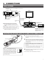
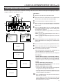
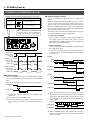
CAUTION This section of instruction manual is specially edited for service manual with modified contents. It is not recommended to use this section for the substitution of the original instructions included in the merchandise. COLOR VIDEO CAMERA KY-F58 INSTRUCTIONS FREEZE Digital ry Memo For Customer Use: Enter below the Serial No. which are located on the bodys. Retain this information for future reference. Model No. KY-F58 Serial No. [U Ver.] CAUTION RISK OF ELECTRIC SHOCK DO NOT OPEN TO REDUCE THE RISK OF ELECTRIC SHOCK, DO NOT REMOVE COVER (OR BACK). NO USER SERVICEABLE PARTS INSIDE. REFER SERVICING TO QUALIFIED SERVICE PERSONNEL. CAUTION: To prevent electric shocks and fire hazards, do NOT use other than specified power source. CAUTION : The lightning flash with arrowhead symbol, within an equilateral triangle is intended to alert the user to the presence of uninsulated “dangerous voltage” within the product's enclosure that may be of sufficient magnitude to constitute a risk of electric shock to persons. The exclamation point within an equilateral triangle is intended to alert the user to the presence of important operating and maintenance (servicing) instructions in the literature accompanying the appliance. Due to design modifications, data given in this instruction book are subject to possible change without prior notice. Information for USA This device complies with Part 15 of the FCC Rules. Changes or modifications not approved by JVC could void the user's authority to operate the equipment. INFORMATION (FOR CANNADA) RENSEIGNEMENT (POUR CANADA) • This Class B digital apparatus complies with Canadian ICES-003. • Cet appareil numérique de la classe B est conforme à la norme NMB-003 du Canada. Changes or modifications not approved by JVC could void the user's authority to operate the equipment. This unit is designed for professional use only. WARNING: TO PREVENT FIRE OR SHOCK HAZARD, DO NOT EXPOSE THIS UNIT TO RAIN OR MOISTURE. [E Ver.] IMPORTANT The wires in this mains lead are coloured in accordance with the following code: EARTH GREEN-AND-YELLOW: NEUTRAL BLUE: LIVE BROWN: As the colours of the wires in the mains lead of this apparatus may not correspond with the coloured markings identifying the terminals in your plug, proceed as follows. The wire which is coloured GREEN-AND-YELLOW must be connected to the terminal in the plug which is marked with the letter E or by the safety earth symbol or coloured GREEN or GREEN-AND-YELLOW. The wire which is coloured BLUE must be connected to the terminal which is marked with the letter N or which is coloured BLACK. The wire which is coloured BROWN must be connected to the terminal which is marked with the letter L or coloured RED. WARNING — THIS APPARATUS MUST BE EARTHED. 2 Revised in August 1998 WARNING: TO PREVENT FIRE OR SHOCK HAZARD, DO NOT EXPOSE THIS APPLIANCE TO RAIN OR MOISTURE. Changes or modifications not approved by JVC could void the user's authority to operate the equipment. This unit is designed for professional use only. Thank you for purchasing the JVC KY-F58 Color Video Camera. CONTENTS FEATURES .............................................................................. 3 BASIC CONFIGURATION ........................................................ 3 1. INTRODUCTION PRECAUTIONS ON PROPER USE ........................................ 4 2. CONTROLS, INDICATIONS AND CONNECTORS CAMERA CONTROL UNIT [Panel side] .................................. 5 CAMERA CONTROL UNIT [Rear side] .................................... 7 CAMERA HEAD ....................................................................... 8 FEATURES • High quality 1/3” and 3CCD format camera • The camera head can be dismantled to produce a compact component. • A built-in Frame Memory function enables a STROBE SYNC and RANDOM TRIGGER to operate the camera without adding any further equipment. • Quick set-up can be achieved with a “Scene File”. • Direct connection to various units is available with various output signals such as RGB, VBS, Y/C and a color difference component. • RS-232C can be interface. BASIC CONFIGURATION 3. CONNECTIONS BASIC SYSTEMS .................................................................... 9 MOUNTING THE OPTIONAL LENS (T14 x 5.5MD) TO THE CAMERA HEAD ....................................................................... 9 HOW TO MOUNT THE CAMERA HEAD ............................... 10 CONNECTING THE CAMERA HEAD AND CCU (CAMERA CONTROL UNIT ) ................................ 10 SYSTEM APPLICATION ........................................................ 11 CAMERA HEAD CAMERA MOUNTING BRACKET (With two screws) 4. BASIC ADJUSTMENTS BEFORE USE (Be sure) MONITOR ADJUSTMENT ..................................................... 12 WHITE BALANCE ADJUSTMENT ......................................... 13 WHITE SHADING ADJUSTMENT ......................................... 14 FULL TIME AUTO-WHITE FUNCTION .................................. 14 FREEZE 5. OPERATION FILE SETTING ....................................................................... 15 MANUAL OPERATION .......................................................... 17 CAMERA CONTROL UNIT 6. SETTING ON THE MENU SCREEN MENU OPERATION ............................................................... 18 MENU SCREEN FLOW ......................................................... 18 VIDEO LEVEL SCREEN ........................................................ 19 WHITE BALANCE SCREEN .................................................. 20 FREEZE SCREEN ................................................................. 21 PROCESS SCREEN .............................................................. 23 TOTAL SETTING SCREEN .................................................... 25 CAMERA CABLE (5m) AC CABLE (2m) 7. OTHERS TECHNICAL INFORMATION ................................................. 26 SPECIFICATIONS .................................................................. 29 LABEL (where you can write the file name and stick to the panel for convenience) PRECAUTION The camera head and camera control unit must have the same serial number. Each set of units has the same serial number when it is shipped out from the factory in order to guarantee its best performance. see subsection 1.8 of this service maual 3 1. INTRODUCTION PRECAUTIONS ON PROPER USE • When recording an important event, be sure to try the camera first before using it in order to check that the camera operates properly. • JVC does not guarantee the contents of a recording if the color video camera, VCR or video cassette malfunctions during recording. 䡵 Unique phenomenon of CCD 䢇 SMEAR AND BLOOMING Due to the physical structure of the CCDs in this camera it is possible to induce vertical streaking which is called smear when shooting a light source with high luminance. Another effect is the spreading of light around a bright light or object called Blooming. To protect your image against lens flare (internal lens reflections), JVC has adopted a CCD which has less of these phenomenon, however, please be careful when shooting a light source with high luminance. SMEAR Vertical streaks trailing from a bright object. Bright object (i.e. light bulb, sun, etc.) BLOOMING Bright portion bleeds MONITOR SCREEN 䢇 When stripe pattern or lines are shot, they may become jagged. 䢇 White dot Whit dots may appear on a screen when operating at high temperature. 䡵 Please turn off the power switch when camera is not in use. 䡵 RS-232C INTERFACE With regard to CONTROL COMMAND etc., please consult with your local JVC authorized service dealer. 䡵 HANDLING PRECAUTIONS 䢇 Storage Avoid using or placing the unit in places; • subject to extreme heat or cold; • with excessive dirt or dust; • with high humidity or moisture; • subject to strong vibrations or on an unstable surface • subject to smoke or vapor such as near a cooking stove; • also do not leave the unit for long hours in a parked car under direct sunlight or near room heating equipment. 䢇 Ambient Temperature Ambient temperature influence to an image sensing device. Make sure to operate the camera in the temperature range of –5˚C to 45˚C. 䢇 Ventilation holes A malfunction may be caused if heat is not properly ventilated. Make sure that the cooling fan ventilation holes are not blocked by an obstruction. 䢇 Effects of strong electric waves and magnetism To avoid picture interference and color variation, do not use the camera near a radio, TV antenna, transformers or motors which generate strong magnetic field. 䢇 COMPATIBLE LENSES The lens mount for this camera, KY-F58 is a C-Mount, however, there remain some lenses adopting a C-Mount which cannot be used because of camera limitations. Refer to “MOUNTING THE OPTIONAL LENS (T14 x 5.5MD) TO THE CAMERA HEAD” on page 9. The KY-F58 is not equipped with a back focus adjustment feature, therefore a lens with this feature should be mounted. 䢇 EFFECT FROM A WIRELESS MICROPHONE When using a wireless microphone or a receiver, noise interference might be pick-up during recording. Please check this before using. 䢇 CLEANING THE BODY When cleaning the cabinet, wipe it with soft cloth. Do not use benzene or thinner as these may deform or discolor the cabinet surface. To remove excessive dirt, clean the unit with a mild detergent diluted with water, then wipe it with dry cloth. Note: CAMERA MOUNTING Make sure to mount the camera firmly. 4 2. CONTROLS, INDICATIONS AND CONNECTORS Camera Control [Panel side] LOCK 6 8 9 MENU ITEM+ SET ITEM- DATA+ ON BARS ON 1 2 3 4 RESET DATA- OFF 5 12 11 4 3 2 10 7 CAMERA CONTROL UNIT KY-F58 PULL OPEN FILES MENU 1 13 2 FREEZE 3 SELECT 4 MEMORY POWER 1 TO CAMERA WHITE PAINT VIDEO LEVEL SET FULL AUTO R LEVEL ON B OFF 14 PAINT 15 1 16 17 [POWER] power switch and its LED 18 7 This is the ON/OFF power switch. When power is supplied the LED light. 2 [FREEZE] freeze button and its LED 8 4 For the 5 to 10 , refer to the “6. SETTING ON THE MENU SCREEN” on the page 18. 5 [SELECT] select button Each time this button is pressed, the file changes. 6 9 [MENU] menu button [DATA+, DATA–] data buttons When the menu screen is displayed, data of each item can be changed. For the step 5 to 9 , refer to “6. SETTING ON THE MENU SCREEN” on the page 18. [FILES] file selected LEDs When the [SELECT] button 5 is pressed, the LED for the selected file lights. Each time the SELECT button is pressed, the file LED changes 1 2 3 4 in turn. [ITEM+ (BARS), ITEM–] item buttons • When ITEM+ button is pressed on the normal screen, the color bar signal is output from output connectors 20 , 21 and 22 . When pressing this again, it returns to the normal screen. • When the menu screen is displayed ,the required item can be selected. [MEMORY] memory button Select one of the FILES LEDs, No. 1 to 4 4 with the SELECT button 5 . Then press and hold MEMORY button for more than 2 seconds to register the value set at the MENU screen to be the selected file. Refer to the “FILE SETTING” on page 15. [SET] set button. To choose the item on the MENU screen, press this button to display the sub-menu screen. The video signal can be frozens by this button. When the freeze button is pressed, the LED light. When the freeze is released, the LED turns off. Refer to the “MANUAL OPERATION” on page 17. 3 19 10 [LOCK] lock switch When the lock switch is “ON”, all functions except the Power switch 1 , the Freeze button 2 , and the select button 5 cannot be operated. 11 [RESET] reset button When this button is pressed, the set values for each FILE are reset to the initial values set at factory. Refer to “RESET” on the page 16. When this button is pressed, “on screen” signals are output from connectors 20 , 21 and 22 to display the MENU screen. When again pressing this button, the normal screen is resumed. see subsection 1.6.2 of this service maual 5 2. CONTROLS, INDICATIONS AND CONNECTORS (Cont’d) Camera Control [Panel side] (Cont’d) 12 Set up switch 18 This switch changes the FILE setting and the RANDOM TRGGER setting. Change the setting according to the desired use. 1 2 3 4 This adjusts the video level automatically by varying iris, shutter speed and GAIN (electrical sensitization) automatically according to the brightness of an object. The LED light during Full/Auto mode. Each time the button is pressed, the ON/OFF function operates in turn. • Auto adjustment for iris can be performed only when an auto iris lens is used and the LENS item is set to AUTO. • Max. GAIN value for the ALC can be set at the MENU screen. For the 18 and 19 , refer to the “MANUAL OPERATION” on page 17. SW1, 2 FILE setting Refer to "FILE SETTING" on page 15. SW3 RANDOM TRIGGER setting Refer to "Random Trigger Function" on page 28. ON c SW4 Not available 13 COVER To carry out the menu operation, pull the cover towards you to open it. 14 [TO CAMERA] camera connector Connect the camera head with the provided cable (5m). 1 2 5 10 Connector view from the main unit front 15 (20-pin connector, female) 19 6 11 16 20 15 Pin No. Signal Pin No. Signal 1 2 3 4 5 6 7 8 9 10 GND WEN B CLK DATA CS HE SHCT IFHB IFVS G 11 12 13 14 15 16 17 18 19 20 CS LE IRIS CTL/IRIS Y –10V –5V R VIDEO SHIELD 20V 15V 5.5V LENS GND [PAINT R] paint R adjust knob This is the knob which adjusts the R(Red) level of the paint and manual white balance. Turning the knob to the right will increase red. For the adjust knob 15 and 16 , refer to the “MANUAL OPERATION” on page 17. 16 [PAINT B] paint B adjust knob This is the knob which adjusts the B (Blue) level of the paint and manual white balance. Turning the knob to the right will increase blue . 17 [WHITE PAINT SET] When this button is pressed, it becomes AUTO WHITE mode. Refer to the “WHITE BALANCE ADJUSTMENT” on page 13. 6 [VIDEO LEVEL FULL AUTO] full auto button and its LED 19 [LEVEL] video level adjust knob This knob varies video level. Turning it to the right increases the video level and turning it to the left reduces the video level. 2. CONTROLS, INDICATIONS AND CONNECTORS (Cont’d) CAMERA CONTROL [Rear side] (Cont’d) 25 AC- INPUT 24 RS-232C SEE INSTRUCTION MANUAL 23 22 EXT REF VD 21 20 OUTPUT HD/VBS LENS REMOTE FLASH WEN FREEZE 28 29 30 31 VIDEO Y/C EXT TRIGGER RGB/COMPONENT SIGNAL EARTH 26 27 [Y/C] Y/C output signal connector (4 Pin) 20 25 This connector outputs Y/C separated video signal. 4 3 2 1 View from the rear of the KY-F58 (4-pin connector, female) 21 Pin No. Signal 1 2 3 4 GND (ground) GND (ground) Luminance (Y, 1 V(p-p), 75-ohm) Chroma signal (C, 0.286 V (p-p), 75-ohm) [U Ver.] (C, 0.3 V (p-p), 75-ohm) [E Ver.] [RS-232C] Communication port (D-Sub 9Pin) Connect to an RS-232C interface in a personal computer or other control unit. Use a cross cable for connection. 1 View from the rear of the KY-F58 (9-pin connector, male) 6 5 Detail Pin No. Detail 1 2 3 4 5 NC RxD TxD DTR GND 6 7 8 9 DSR RTS CTS NC [AC INPUT] AC Power connector It connects with a provided AC cable to a standard AC120V electric outlet. 1 View from the rear of the KY-F58 (9-pin connector, female) 9 26 9 Pin No. [RGB/COMPONENT] RGB/Component output connector (9Pin) This is the RGB/Component signal output connector. To switch between the RGB and the COMPONENT on the MENU screen. Refer to the “TOTAL SETTING SCREEN” on page 25. 5 6 Pin No. Signal Pin No. Signal 1 2 3 4 5 GND GND R/R-Y G/Y B/B-Y 6 7 8 9 VBS SYNC GND GND [SIGNAL EARTH] signal ground terminal This is not a ground for safety from electrical shock. It is a GND for signals among units. [LENS REMOTE] lens remote control connector It connects to the lens remote control unit (optional). Refer to the “SYSTEM APPLICATION” on page 11. 9 1 2 8 10 22 [VIDEO] Video output connector (BNC) 7 12 3 11 This is the composite video signal output connector. 23 [HD/VBS] HD/VBS sync signal input connector (BNC) This connector inputs HD (Horizontal sync signal) or VBS (Composite video signal) to synchronize the unit. Refer to the “SYSTEM APPLICATION” on page 11. 24 [VD] VD sync signal input connector (BNC) This connector inputs VD (vertical sync signal) to synchronize the unit., 4 6 View from the rear of the KY-F58 (12-pin connector, female) 5 Pin No. Signal Pin No. Signal 1 2 3 4 5 6 SERVO SELECT(F) SERVO SELECT(Z) GND IRIS C/L IRIS CTL 12V 7 8 9 10 11 12 COM FOCUS CTL ZOOM CTL SERVO SELECT(I) COM (+V) COM (–V) Revised in August 1998 7 2. PARTS NAMES AND FUNCTIONS (Cont’d) CAMERA CONTROL [Rear side] (Cont’d) 29 [FLASH] Flash signal output connector (BNC) [FREEZE] freeze input connector 31 This is a trigger input signal connector from an external source. It connects with an external trigger unit such as foot switch, etc. A negative electrode signal with a pulse width of 20µ sec. to 50µ sec. and a pulse interval of 40 msec. or more should be input for the trigger signal. Refer to the “FREEZE SCREEN” on page 21. When the FREEZE item is set to the FLASH, a flash signal is output from this connector according to FREEZE input. It is recommended to be used when the unit is operated with a flash. Refer to the “SYSTEM APPLICATION” on page 11. Refer to the “FLASH Function” on page 28. 30 [WEN] write enable signal output connector (BNC) It outputs the write enable signal. Connect to the image processing unit, etc. . Refer to the “SLOW SHUT FUNCTION” on page 27. Refer to the “Random Trigger Function” on page 28 CAMERA HEAD POWER 5 7 1 6 TO CCU LENS 2 3 4 1 Lens mount This is where the lens is to be mounted. It fits to the C mount lens. Refer to “MOUNTING THE LENS (T14X5.5MD) TO THE CAMERA HEAD” on page 9. 2 When the power is supplied to a camera head, this LED lights. This is to connect a camera control unit (CCU) with a provided cable (5 m). Refer to the “CONNECTING THE CAMERA HEAD AND CCU” on page 10. 1 Camera mounting bracket (Accessory) 5 2 10 15 6 11 19 1/4 inch screw hole for camera mounting to a tripod These are for mounting the camera to a fixed or rotating table, etc. 4 [TO CCU] CCU connector 6 The camera mounting bracket is not installed on the camera when it is shipped from the factory. Install it on the top or bottom of the camera according to your requirements using the two provided camera mounting bracket fixing screws 4 . Refer to the “HOW TO MOUNT THE CAMERA HEAD” on page 10. 3 [POWER] power supply LED 5 16 View from the rear of the camera head (20-pin connector, male) For the signal names, refer to the “ 14 [TO CAMERA]” on page 6. 20 [LENS] lens connector 7 This is to connect the lens to be used. Refer to the “MOUNTING THE OPTIONAL LENS (T14 X 5.5MD) TO THE CAMERA HEAD” on page 9. The provided fixing screws for camera mounting bracket (two of M2.6 x 6 mm) 7 8 Caution: Make sure to use the provided screws. Do not use a screw longer than 6 mm because it may cause a malfunction. 6 5 3 2 4 Pin No. Signal Pin No. Signal 1 LENS SEL 5 SERVO SEL 2 GND 6 ZOOM CTL 3 IRIS CTL/IRIS Y 7 FOCUS CTL 4 15V 8 IRIS CTL/IRIS Y 1 View from the rear of the camera head (8-pin connector, female) 8 3. CONNECTIONS BASIC SYSTEMS Mounting the optional lens (T14 X 5.5MD) to the camera head (See page 9.) male Lens (T14 x 5.5 MD) Monitor Camera head To CCU COLOR VIDEO female KY-F58 CAMERA To LENS How to mount the camera head (See page 10.) [LENS REMOTE] Provided cable (5m) Connecting the camera head and CCU (See page 10.) OUTPUT CAMERA CONTROL UNIT KY-F58 PULL OPEN FILES MENU 1 䢇 Recommended Remote Controllers • TCR-201F (CANON) for positioning control 2 3 SELECT FREEZE 4 MEMORY LENS REMOTE terminal on the rear panel POWER male TO CAMERA WHITE PAINT VIDEO LEVEL SET FULL AUTO R LEVEL ON B OFF Note: PAINT To CAMERA When using an extension cable, the screen flickers slightly during the focusing operation.. CCU (Camera Control Unit) female LENS remote control • The LENS remote controller should be connected to the REMOTE terminal on the rear panel of the CCU or to LENS REMOTE on the lens. • RMD-10 (FUJINON) for speed control MOUNTING THE OPTIONAL LENS (T14 X 5.5MD) TO THE CAMERA HEAD Camera head 1. Remove the lens mount cap for the camera. 3. Be careful no dust gets into the mounting hole when you remove it. Screws 2. Attach the screw of the camera head mount section to that Mount fastening ring of the lens mount section. Turn the mount fastening ring slowly clockwise and fix the lens to the camera head by screwing it firmly. Lens 2. To change the attitude angle of the lens rotating direction. 1 Turn the mount fastening ring counter-clockwise from the lens side. 2 Turn the lens slowly to adjust the attitude angle, and fasten it again firmly with the mount fastening ring. Note: The KY-F58 is not equipped with a lens. When a lens other than the T14x5.5MD of the 3-CCD C-mount lens is used, it may cause the KY-F58 to malfunction. When such a lens is used, the lens' height should not be more than 4 mm above the lens mount surface. 4mm or less 3. Plug in the lens cable to the LENS connector of the camera head and fasten it firmly. Lens For more details, refer to the Instructions for the Lens. 9 3. CONNECTIONS (Cont’d) HOW TO MOUNT THE CAMERA HEAD Camera mounting bracket 䡵 How To Mount The Bracket 䡵 How To Mount The Camera The camera mounting bracket is not installed on the camera when it is shipped from the factory. Install it on the top or bottom of the camera according to your requirements using the two provided camera mounting bracket fixing screws. Note: Camera mounting screw hole (1/4 inch) Be sure to use the provided bracket fixing screws when installing the camera. Screws longer than 6 mm may cause a malfunction. M2.6 X 6mm Drop prevention wire 6mm Camera head When this unit is mounted to a fixed or a rotating table, fix it to the camera mounting screw hole located on the camera mounting bracket. • To prevent dropping, when this unit is mounted to a fixer or a rotating table, fix it firmly by using the rotation prevention hole. Rotation prevention hole 䡵 Drop prevention • When this unit is installed on a ceiling or a wall, special care is required. Do not try to install it by yourself. Leave this to a specialist. If the unit drops from the ceiling or the wall, it may injure people or cause an accident. • To prevent the unit from dropping, install it securely to the place, and attach it with a wire, etc. For the installation, use the bracket fixing screw hole located on the side where there is no camera mounting bracket attached.(M2.6 x 6 mm) Give thought to the length of the drop prevention wire. CONNECTING THE CAMERA HEAD AND CCU (CAMERA CONTROL UNIT) Camera head female male arrow arrow mark mark female male Tight until there is no gap between two cables. arrow mark CCU female female male male male female Camera cable for extension Provided camera cable ● When connecting a cable to the camera head and CCU, place the arrow mark on the connector on top. Then insert it firmly until there is no gap with the terminal by tightening it. Note: ● For extending cable, use the optional camera cables. Make sure to loosen the connector ring completely before see service manual 5 m camera cable: VC-P805 unplugging the cable, otherwise the connector may be dam10 m camera cable: VC-P810 (No. 60116) aged. The maximum cable length is up to 25 m. Note: When the cable is extended to 25 m, JVC guarantees only the operation and not the performance. ● When connecting cables, match the arrow marks on each cables. Also, make sure to connect a male connector and a female connector. 10 3. CONNECTIONS (Cont’d) Camera head VD Microscope adapter HZ-M161/M162/M163 HD/VBS (Front panel) AC- INPUT RS-232C SEE INSTRUCTION MANUAL LENS REMOTE To 120V AC EXT REF VD LENS REMOTE OUTPUT HD/VBS VIDEO Y/C EXT TRIGGER FLASH FLASH WEN FREEZE WEN KY-F58 COLOR VIDEO CAMERA SYSTEM APPLICATION ; ; Microscope Flash light RGB/COMPONENT FREEZE VIDEO VD HD/VBS RGB WEN VIDEO IN Lens remote control Foot switch, etc. 䡵 To start a flash light with a foot switch • Connect an external trigger such as a foot switch to the FREEZE connector. • Connect a flash light to the FLASH connector. • Set the FREEZE MENU to “FLASH”. Monitor Image processing unit Note: Before starting the connection, please thoroughly read the Technical Information on page 26 and following. 䡵 To output an image from the KY-F58 under the timing of the image processing unit • Connect an external sync signal of the image processing unit to the VD and HD/VBS connector of this unit. • Connect the image output connector to the image input connector of the image processing unit. 䡵 To output an image to the image processing unit under the timing of the KY-F58 • Connect the WEN (Write Enable) connector of the KY-F58 to the image processing unit. • Connect the image output connector to the image input connector of the image processing unit. 11 4. BASIC ADJUSTMENTS BEFORE USE (Be sure) MONITOR ADJUSTMENT AC- INPUT RS-232C SEE INSTRUCTION MANUAL EXT REF VD LENS REMOTE Perform the adjustments for color, contrast and luminance by displaying the color bar signal built into the KY-F58 on the monitor. OUTPUT HD/VBS VIDEO Y/C MONITOR RGB/COMPONENT EXT TRIGGER FLASH WEN FREEZE 1. Connect a color video monitor to the VIDEO OUPUT terminal of the KY-F58. 2. Open the cover and switch the Lock switch to OFF. 3. Press the “ITEM+” button to output the color bar signal (the 1. color bar conforms to the SMPTE [U Ver.] or EBU [E Ver.] ) 4. While displaying the color bar, set the BLUE CHECK of the To Monitor 2. 3. CAMERA CONTROL UNIT KY-F58 LOCK MENU ITEM+ SET ITEM- FILES DATA+ 1 ON 2 5. [U Ver.] FREEZE 3 4 BARS ON 1 2 3 4 RESET DATA- SELECT MEMORY OFF Turn the CHROMA adjustment volume on the monitor to adjust the color bar so that the brightness of 1 and 8 , and 7 and 14 become the same. [E Ver.] Turn the CHROMA adjustment volume on the monitor to adjust the color bar so that the brightness of 1 and 7 become the same. POWER TO CAMERA WHITE PAINT VIDEO LEVEL SET FULL AUTO R LEVEL ON B OFF PAINT 6. [U Ver.] SMPTE type color bars [U Ver.] White Yellow Cyan 1 2 3 Blue 8 Green Magenta Black Magenta Black 9 Red Blue 5 6 7 Cyan Black White 12 13 14 4 10 11 Blue White Black 15 16 17 monitor to “ON”. The screen becomes blue only mode and color bar becomes blue stripe pattern. 18 19 20 21 EBU type color bars [E Ver.] While the BLUE CHECK is ON, turn the PHASE adjustment volume of the monitor to adjust the color bar, so that the brightness of 3 and 10 , and 5 and 12 become the same. [E Ver.] While the BLUE CHECK is ON, turn the PHASE adjustment volume of the monitor to adjust the color bar, so that the brightness of 3 and 5 become the same. 7. [U Ver.] In case the brightness of 1 and 8 , and 7 and 14 change when carrying out the PHASE adjustment, start the procedure again from step 4 . [E Ver.] In case the brightness of 1 and 7 change when carrying out the PHASE adjustment, start the procedure again from step 4 . 8. Set the BLUE CHECK of the monitor to OFF to return to the White Yellow Cyan Green Magenta Red Blue Black normal screen (to display all colors, R, G and B). 9. [U Ver.] only Adjust the BRIGHT adjustment volume of the monitor, so that 18 and 19 disappear and 20 becomes visible. 1 2 3 4 5 6 7 8 10. When the adjustment is completed, press the “ITEM+” button again to return to the normal screen. 12 Revised in August 1998 4. BASIC ADJUSTMENTS BEFORE USE (Cont’d) WHITE BALANCE ADJUSTMENT The color of light (color temperature) is different according to the color source. When the main light source lighting an object is changed, readjust the white balance as well. < How To Set > 4.5.6. 5.6. 2. 10. 3.7. 1. 1. 2. LIGHT CAMERA CONTROL UNIT KY-F58 LOCK ITEM+ SET ITEM- FILES DATA+ 1 2 3 FREEZE 4 BARS ON 4. MENU ON 1 2 3 4 RESET DATA- SELECT 3. 4. MEMORY OFF POWER TO CAMERA WHITE PAINT VIDEO LEVEL SET FULL AUTO R LEVEL ON B OFF 5. PAINT FULL AUTO button 9. CURSOR Setting value Item – – – MENU – – – MENU SCREEN : 3200K : AUTO : OFF : : : 6. WHITE BALANCE SCREEN 7. 8. A U T O WH I T E OP E R A T I ON AUTO WHITE OPERATION OK A U T O WH I T E ERROR : OVER LIGHT Move a cursor to the “2. WHITE BALANCE” with the ITEM button. Then press the SET button to display the “WHITE BALANCE” screen. Select the COLOR TEMP item on the “WHITE BALANCE” screen with the ITEM button. (Setting value starts blinking when the required item is selected.) The setting value suitable for usage condition can be selected with the DATA button. 9. Select the “WHITE BAL” item on the “WHITE BALANCE” screen with the ITEM button. Set the setting value to AUTO with the DATA button. Return to the normal screen by pressing the MENU button twice. Place a white object under the same lighting condition as the shooting object, and zoom in to fill the screen with white. Press the WHITE PAINT SET button ●While AUTO WHITE is being operated, “OPERATION” signals are output from each OUTPUT connector. ●When the white balance is adjusted correctly, “OK” is displayed. ERROR : OBJECT (object in an unfavorable condition) When there is not enough white color in the object or the color temperature is not suitable, this error message is displayed. Change the object into a white object and readjust the white balance. AUTO WHITE OK OBJECT IN AN UNFAVORABLE CONDITION Press the MENU button to display the MENU screen. ●Error display: A U T O WH I T E A U T O WH I T E NG : OBJECT Select the “FILE” for the white balance to be adjusted by the SELECT button. (The LED for the selected file lights.) 3200 K: For a low color temperature light source such as a halogen lamp, etc. . 5200 K: For a high color temperature light source such as the sun, etc. . – – – WHITE BALANCE – – – COLOR TEMP WHITE BAL SHADING MODE LEVEL<R> LEVEL<G> LEVEL<B> 1:VIDEO LEVEL.. 2:WHITE BALANCE.. 3:FREEZE.. 4:PROCESS.. 5:TOTAL SETTING.. Open the cover and set the Lock Switch to OFF. A U T O WH I T E ERROR : LOW LIGHT SHORTAGE OF LIGHT ERROR : LOW LIGHT (shortage of light) This message is displayed when the light is dark. Turn the light up and readjust the white balance. ERROR : OVER LIGHT (excess of light) • This message is displayed when the light is too bright. Turn the light down and readjust the white balance. • If the color temperature of the object is changed when turning the light down, press the FULL AUTO button on the panel side and readjust the white balance. 10. Press the MEMORY button to register the white balance in EXCESS OF LIGHT the FILE for two seconds. If color is added to the top or bottom of the screen after adjusting the white balance, carry out the white shading adjustment explained in the next section. 13 4. BASIC ADJUSTMENT BEFORE USE (Cont’d) WHITE SHADING ADJUSTMENT Green or magenta color appears on the top or bottom of the screen, this is because the white balance is adjusted at the center of the screen but not at the top or bottom of the screen. This is caused by the characteristics of a lens and to compensate it is called white shading compensation. <How To Set > 1. 2. 3.4. 6. After performing the WHITE BALANCE ADJUSTMENT procedure 1. to 10., carry out the following settings. CAMERA CONTROL UNIT KY-F58 LOCK MENU ITEM+ SET ITEM- FILES DATA+ 1 ON 2 FREEZE 3 4 BARS ON 1 2 3 4 RESET DATA- SELECT MEMORY OFF POWER TO CAMERA WHITE PAINT VIDEO LEVEL SET FULL AUTO R LEVEL ON B OFF 1. 2. Display the MENU screen by pressing the MENU button. Move a cursor to “2. WHITE BALANCE” with the ITEM button, then press the SET button to display the “WHITE BALANCE” screen. PAINT 3. Set the SHADING MODE item to the “MANUAL” by pressing the DATA+ button or the DATA– button. 4. Change the items on the LEVEL<R>, LEVEL<G> and – – – WHITE BALANCE – – – : : : : : : COLOR TEMP WHITE BAL SHADING MODE LEVEL<R> LEVEL<G> LEVEL<B> 3200K AUTO MANUAL NORMAL NORMAL NORMAL LEVEL<B> with the DATA+ and DATA- button while watching the monitor screen. When the number increases, the color on the bottom of the screen is suppressed and the color on the top is emphasized. WHITE BALANCE SCREEN 5. When the settings for all channels (R channel, G channel, B channel) are completed, carry out the white balance adjustment again. 6. To register the setting values of the white shading to the FILE, return to the normal screen then press the MEMORY button for 2 seconds or more. FULL TIME AUTO-WHITE FUNCTION With the FULL TIME AUTO-WHITE ADJUSTMENT function, even if the lighting condition is changed, this function will trail it automatically in order to adjust the white balance to the optimum condition. 1. 2. 3. <How To Set > CAMERA CONTROL UNIT KY-F58 LOCK MENU ITEM+ DATA+ ON FILES 1 2 FREEZE 3 4 BARS SET ON 1 2 3 4 RESET ITEM- DATA- SELECT MEMORY OFF POWER TO CAMERA WHITE PAINT ton, then press the SET button to display the “WHITE BALANCE” screen. VIDEO LEVEL SET FULL AUTO R LEVEL 1. Display the MENU screen by pressing the MENU button. 2. Move a cursor to “2. WHITE BALANCE” with the ITEM but- ON B OFF 3. Set the item WHITE BAL to the FAW with the DATA+ and PAINT DATA- button. Note: – – – WHITE BALANCE – – – COLOR TEMP WHITE BAL SHADING MODE LEVEL<R> LEVEL<G> LEVEL<B> : 3200K : FAW : OFF : : : If the whole screen consists of one color, an object has many colors or the color temperature of the light source varies, the appropriate full time auto white balance may not be adjusted. In this case, carry out the “WHITE BALANCE ADJUSTMENT” on page 13. WHITE BALANCE SCREEN Color temperature 2500 K 3000 K 4000 K Red-ish 5000 K 6000 K White-ish Incandescent lamp Halogen Fluorescent lamp (Sun light) lamp 7000 K Blue-ish Bright cloudy sky The range of FULL TIME AUTO WHITE function 2800K 14 8000 K 15000 K 5. OPERATION FILE SETTING There are four scene files to be set by dip switch depending on the operating conditions. Scene File A including four sub files are all set to the standard shipment setting values. Change the settings according to the requirements. Scene File B, C and D should be set to required file settings before use such as Slit inspection, Microscope 1 , Microscope 2 , etc. Note: Before carry out operations below, make sure the LOCK switch is turned OFF. 䡵 Scene File Setting Select the “Scene File” with the dip switch 1 and 2 according to the purposes. Scene File CAMERA CONTROL UNIT KY-F58 LOCK MENU ITEM+ SET ITEM- DATA+ ON FILES 1 2 3 B ON SELECT button ON A DIP switch Dip switch setting FREEZE MEMORY OFF POWER TO CAMERA WHITE PAINT 1234 VIDEO LEVEL SET FULL AUTO R C ON SELECT LEVEL ON B D OFF ON ON DATA- 1234 4 BARS 1 2 3 4 RESET 1234 Example for use 1. OFF Standard 2. OFF setting 3, 4. Do not switch over 1. ON Slit 2. OFF Inspection 3, 4. Do not switch over 1. OFF Microscope 1 2. ON 3, 4. Do not switch over 1234 1. ON 2. ON Microscope 3, 4. Do not switch over 2 PAINT Note: Switch off the power when switching the Scene File over. If it is carried out while the power is ON, it will not be changed. 䡵 FILE Setting Each Scene File has four of sub files (FILE) to be set. Each time the SELECT button is pressed, it is switched in the order of FILE1 FILE2 FILE3 FILE4 . It takes 1 second to switch over the FILE. LED blinks rapidly during the FILE switching operation. Note: Do not perform other operations during the LED blinking, it may cause the KY-F58 to malfunction. The FILE setting is completed when the LED stops blinking, and lights. 䡵 Changing setting values Changing setting values The setting value is changed for each file. Refer to the “6. SETTINGS ON THE MENU SCREEN” on page 18. MEMORY button CAMERA CONTROL UNIT KY-F58 LOCK MENU ITEM+ SET ITEM- DATA+ ON FILES 1 2 3 FREEZE 4 BARS ON 1 2 3 4 RESET DATA- SELECT MEMORY OFF POWER TO CAMERA WHITE PAINT VIDEO LEVEL SET FULL AUTO R LEVEL ON B OFF PAINT 䡵 Registration to the FILE Setting values can be registered to each FILE. Press the MEMORY button for 2 sec. or more for registration. The setting value is registered to the FILE which LED lights. It takes approx. 2 sec. for registration. During the registration, the LED blinks slowly. The FILE registration is completed when the LED stops blinking, and lights. Note: • To register a value which has been changed on the MENU screen or with a volume level knob, make sure to register any changes in the selected file. If the power is turned off without registering the changes, they will be automatically erased. • Do not perform other operations during the LED blinking, it may cause the KY-F58 to malfunction. 15 5. OPERATION (Cont’d) FILE SETTING (Cont’d) 䡵 RESET Initial Values of Scene File A Item Initial Values LENS TYPE AUTO IRIS CONTOROL AUTO SHUTTER NORMAL ---------- LEVEL 0 dB GAIN Note: Do not perform any other operations during the resetting. Otherwise, the values will not be initialized properly. ---------- LEVEL ALC MAX +18 dB IRIS DETECT NORMAL DETECT AREA NORMAL COLOR TEMP 3200K WHITE BAL AUTO SHADING MODE OFF tip. ---------- LEVEL < G > ---------- LEVEL < B > ---------NORMAL FREEZE TRG ALTERNATE HI-RESO OFF CAPTURE FRAME RANDOM SHUT ---------- SLOW SHOT ---------- DETAIL NORMAL MASTER BLACK NORMAL NEGA OFF AUTO KNEE OFF KNEE POINT 110% GAMMA ON NORMAL FLARE < B > NORMAL ABL ADJUST D-SUB OUT Initial Values R/G/B ON SYNC OFF LENS CONTROL CONTROLLER INDICATOR CABLE LENGTH Note: The TOTAL SETTING screen will not be initialized. 䢇 All files reset The setting values for all of the 16 files are initialized. 1. Press the RESET button with something which has a pointed tip while pressing the SET button simultaneously. 2. When resetting starts the LEDs for the FILES 1 - 4 are turned The TOTAL SETTING screen will not be initialized. NORMAL TOTAL SETTING Initial Values Item for approx. 3 sec. Note: FLARE < R > ABL LEVEL 2. When the reset starts, the LED for the selected file blinks off for 5 sec. Then the LED of the file selected before the reset blinks for approx. 3 sec. The reset is completed when the LED stops blinking, and lights. 100% WHITE CLIP 䢇 Individual file reset The current selected file setting values are reset to the initial values. 1. Press the RESET button with something which has a pointed LEVEL < R > FREEZE 16 It returns the values set on the MENU screen to the initial values. There are three different RESET items: Individual file reset, All files reset, and Reset for the TOTAL SETTING only. OFF 5M H PHASE 0 SC COARSE 0 SC FINE 0 䢇 Reset for the TOTAL SETTING only The values of the TOTAL SETTING which are common for all files are initialized. 1. Press the RESET button with something which has a pointed tip while pressing the ITEM button simultaneously. 2. When the reset starts, the LED for the currently selected FILE blinks for approx. 3 sec. The reset is completed when the LED stops blinking, and lights. 5. OPERATION (Cont’d) MANUAL OPERATION 䡵 WHITE PAINT CAMERA CONTROL UNIT KY-F58 LOCK MENU ITEM+ SET ITEM- DATA+ ON FILES 1 2 3 FREEZE 4 BARS ON 1 2 3 4 RESET DATA- SELECT MEMORY OFF POWER TO CAMERA WHITE PAINT VIDEO LEVEL SET FULL AUTO R LEVEL ON B OFF PAINT PAINT (R) PAINT (B) The red and blue colors of the video signal from each output can be adjusted with the two adjust knobs PAINT(R) and PAINT (B). The amount of variation possible with the volume controls may be different in the WHITE PAINT mode and the MANUAL WHITE mode. 䢇 Manual White When the item for the WHITE BAL on the WHITE BALANCE screen is set to MANUAL, the red and blue color levels can be adjusted. • Turning the PAINT (R) adjust knob to the right will increase the red and turning it to the left will decrease it. Turning the PAINT (B) adjust knob to the right will increase the blue and turning it to the left will decrease it. <Variable Range> • When the COLOR TEMP is set to 3200K, the color temperature can be changed from 2000K up to 5600K. • When the COLOR TEMP is set to 5200K, the color temperature can be changed from 4500K up to 15000K. 䢇 White Paint When the item for the WHITE BAL on the WHITE BALANCE screen is set to AUTO, the red and blue colors should also be finely adjusted against the white balance which has been set in accordance with the WHITE BALANCE ADJUSTMENT on page 13. • Turning the PAINT (R) adjust knob to the right will slightly increase the red and turning it to the left will slightly decrease it. • Turning the PAINT (B) adjust knob to the right will slightly increase the blue and turning it to the left will slightly decrease it. 䡵 VIDEO LEVEL CAMERA CONTROL UNIT KY-F58 LOCK MENU ITEM+ SET ITEM- DATA+ ON FILES 1 2 3 FREEZE 4 BARS ON 1 2 3 4 RESET DATA- SELECT MEMORY OFF POWER TO CAMERA WHITE PAINT 䢇 Convergence Level Adjustment. The convergence level which is a standard value for the Auto Iris can be finely adjusted. • Turning the LEVEL adjust knob to the right opens the lens iris approximately three diaphragms at the maximum. • Turning the LEVEL adjust knob to the left closes the lens iris approximately three diaphragms at the maximum. VIDEO LEVEL SET FULL AUTO R LEVEL ON B OFF PAINT FULL AUTO LEVEL Full Auto Lens Type Iris Control Other conditions ON – – – MANUAL – Volume Operation Convergence Adjustment Level Convergence Adjustment Level ALC,ALC + EEI,EEI Except for the above OFF AUTO Not functional Convergence Adjustment Level Manual Iris Adjustment – AUTO – MANUAL 䡵 FREEZE 䢇 Manual Iris Adjustment The lens iris can be adjusted from OPEN to CLOSE. • Turning the LEVEL adjust knob to the right opens the lens iris to the IRIS OPEN. • Turning the LEVEL adjust knob to the left closes the lens iris to the IRIS CLOSE. 䢇 Non Operational The video level can not be varied by turning the LEVEL adjust knob. FREEZE CAMERA CONTROL UNIT KY-F58 LOCK MENU ITEM+ SET ITEM- DATA+ ON FILES 1 2 3 FREEZE 4 BARS 1 2 3 4 RESET ON The video signal level at each OUTPUT can be varied with the LEVEL adjust knob. With regard to the amount of the video level variability available at the FULL AUTO button by using the LEVEL adjust knob, refer to the chart on the left. DATA- SELECT MEMORY OFF POWER TO CAMERA WHITE PAINT VIDEO LEVEL SET FULL AUTO R LEVEL ON B When the FREEZE button is pressed, the display LED lights and each output signal is frozen. The LED lights during FREEZE mode. Refer to the “FREEZE SCREEN” on page 21. Refer to the “FLASH Function” on page 28. OFF PAINT 17 6. SETTING ON THE MENU SCREEN MENU OPERATION Note: To register the setting values which are changed on the MENU screen to the FILE, select the FILE with the set up SW and the SELECT button before displaying the MENU screen. Also, make sure to turn off the power before switching the set up SW. 1.7. <How To Operate> 2. 3.5. 6. LOCK MENU ITEM+ SET ITEM- 1. Set the LOCK switch to OFF. 2. Press the MENU button to display the MENU screen. 3. Move the cursor to the required item (SUB MENU) by press- DATA+ ON BARS ON 1 2 3 4 RESET DATA- OFF ing the ITEM+ or ITEM– button. 4.7. CAMERA CONTROL UNIT KY-F58 LOCK MENU ITEM+ SET ITEM- DATA+ ON FILES 1 2 3 FREEZE ITEM+ or ITME– button. 4 BARS ON 1 2 3 4 RESET DATA- SELECT MEMORY OFF POWER TO CAMERA WHITE PAINT VIDEO LEVEL SET FULL AUTO R 4. Press the SET button to display the SUB MENU screen. 5. Select the required item in the SUB MENU by pressing the LEVEL ON B OFF PAINT 6. Change the setting value of the item by pressing the DATA+ or DATA– button. 7. When the change is completed, press the MENU button to return to the normal screen. To prevent from the error operation, set the LOCK switch to ON. Set up switch SELECT button MENU SCREEN FLOW Normal screen CURSOR MENU (SUB MENU SCREEN) MENU – – – MENU – – – 1:VIDEO LEVEL.. 2:WHITE BALANCE.. 3:FREEZE.. 4:PROCESS.. 5:TOTAL SETTING.. MAIN MENU screen – – – SIGNAL LEVEL – – – Move the cursor with the ITEM+ or ITEM- button to select the SUB MENU with the SET button. (Press the MENU button to return to the normal screen.) <Sub Menu screen> VIDEO LEVEL This sets video signals such as shutter, iris, sensitivity, etc. WHITE BALANCE This sets items for WHITE BALANCE and WHITE SHADING. FREEZE This sets items regarding the memory such as timing to input images into the KY-F58 memory, slow shutter function, etc. LENS TYPE IRIS CONTROL SHUTTER LEVEL GAIN LEVEL ALC MAX IRIS DETECT DETECT AREA : : : : : : : : : AUTO AUTO NORMAL ---------0dB ---------+18dB NORMAL NORMAL Note: The data set at the TOTAL SETTING is common to all files. 18 COLOR TEMP WHITE BAL SHADING MODE LEVEL <R> LEVEL <G> LEVEL <B> : : : : : : 3200K AUTO OFF ---------------------------- – – – MEMORY – – – FREEZE FREEZE TRG HI-RESO CAPTURE RANDOM SHUT SLOW SHUT : : : : : : NORMAL ALTERNATE OFF FRAME ------------------- White balance setting menu screen – – – PROCESS(1/2) – – – Memory environment setting screen PROCESS This sets fine settings for output signals such as contour compensation, KNEE POINT, etc. TOTAL SETTING For setting the connection to units other than KY-F58 such as D-SUB terminal, lens control terminal, external sync, etc. – – – WHITE BALANCE – – – Image setting menu screen – – – TOTAL SETTINGS – – – D-SUB OUT ON SYNC LENS CONTROL INDICATOR CABLE LENGTH H PHASE SC CORASE SC FINE : : : : : : : : R/G/B OFF CONTROLLER OFF 5M 0 0 0 Total setting menu screen DETAIL MASTER BLACK NEGA AUTO KNEE KNEE POINT WHITE CLIP GAMMA FLARE<R> FLARE<B> : : : : : : : : : NORMAL NORMAL OFF OFF 100% 110% ON NORMAL NORMAL – – – PROCESS(2/2) – – – ABL LEVEL : ADJUST : NORMAL Process setting screen ITEM+, – button 6. SETTING ON THE MENU SCREEN (Cont’d) VIDEO LEVEL SCREEN Item Functions and operation Variables values LENS TYPE Switch over between AUTO and MANUAL according to the lens to be used. AUTO : Set it when an automatic iris lens is used. MANUAL : Set it when a manual iris lens is used or no lens is used. AUTO MANUAL IRIS CONTROL Switch over between AUTO and MANUAL for iris setting when a automatic iris lens is used. AUTO : Iris can be adjusted automatically. MANUAL : Iris can be adjusted by manually. Note: When AUTO is set, make sure to set the FREEZE item of the FREEZE screen to the NORMAL. AUTO MANUAL SHUTTER This is to change the shutter mode. NORMAL : Fixed with 1/60 [U Ver.] or 1/50 [E Ver.]. : Shutter speed can be changed at the “LEVEL” item. (Fix value) STEP : Shutter speed varies automatically depending on brightness of the object. EEI (Max. approx. 1/1920) [U Ver.] , (Max·approx. 1/1600) [E Ver.] V.SCAN : Adjust the shutter speed to the scanning speed of the computer's monitor, so that the horizontal lines do not appear when taking a shot of the computer monitor. The shutter speed can be varied finely at the “LEVEL” item. Note: This item cannot be set only when the FREEZE item on the FREEZE screen is set to NORMAL. (not available with RANDOM, TRG, FLASH, SLOW SHUT). The shutter speed is set to that at the FREEZE screen . NORMAL STEP EEI V.SCAN LEVEL The shutter speed can be varied when the SHUTTER is set to the V.SCAN or the STEP. Increase shutter speed: Press the DATA+ button. Decrease shutter speed: Press the DATA- button. It is recommended to set the RANDOM SHUT to 1/100 [U Ver.] or 1/120 [E Ver.] in the area with 50 Hz [U Ver.] or 60Hz [E Ver.] to decrease flickers when an object is shot under a fluorescent lamp. Note: When the shutter speed is increased, the light volume may not be high enough. Therefore an adjustment of the lens’ iris or sensitivity is necessary. Also, attention is required to the picture quality because the GAIN is boosted, the sensitivity increases and causes a rough appearance to the picture. [U Ver.] V.SCAN 1/60.6 - 1/9936.4 STEP 1/100,1/250, 1/500,1/1000,1/2000 Sensitivity mode can be changed. 0 dB : Sensitivity does not increase. ALC : GAIN is varied automatically according to brightness. (Max. GAIN can be set at the next item, ALC MAX.) STEP : Sensitivity can be changed at the “LEVEL” item. (Fix value) V.GAIN : GAIN can be varied at the “LEVEL” item. Note: ALC can not be set when the FREEZE item of the FREEZE screen is set to RANDOM TRG, Flash or SLOW. 0 dB ALC STEP V.GAIN The sensitivity can be varied when the GAIN is set to the V.GAIN or STEP. Increase sensitivity: Press the DATA+ button. Decrease sensitivity: Press the DATA- button. V.GAIN +0.2dB - +18.0dB (0.2 dB step) GAIN LEVEL [E Ver.] V.SCAN 1/50.4 - 1/9900.0 STEP 1/120,1/250, 1/500,1/1000,1/2000 STEP +6dB, +9dB, +12dB, +18dB ALC MAX Max. GAIN for the ALC which changes the sensitivity automatically according to brightness. +6 dB: Max. GAIN is 6 dB. +12 dB: Max. GAIN is 12 dB. +18 dB: Max. GAIN is 18 dB. +6dB +12dB +18dB IRIS DETECT The setting value of the detection level in the AUTO IRIS mode can be varied. NORMAL : Normal position PEAK : The max. value (peak level) of the brightness is detected to make the highlight object more clearly. AVG : The average value of the brightness is detected to make the object more clear. NORMAL PEAK AVG Revised in August 1998 19 6. SETTING ON THE MENU SCREEN (Cont’d) VIDEO LEVEL SCREEN (Cont’d) Function and operation Item DETECT AREA Variable values It sets the detection area with the AUTO IRIS mode. Change this according to the condition of use. Detecting area Detecting area Detecting area NORMAL CIRCLE Detecting area Detecting area RECTANGLE FULL NORMAL CIRCLE SQUARE RECTANGLE FULL SQUARE WHITE BALANCE SCREEN Function and operation Item Variable values COLOR TEMP The basic color temperature of the white balance can be set. 3200 K: For low color temperature light source such as a halogen lamp, etc. 5200 K: For a high color temperature light source such as the sun, etc. 3200K 5200K WHITE BALANCE Different modes for the white balance can be set. MANUAL : White balance can be varied manually with the “PAINT R” adjust knob or the “PAINT B” adjust knob. PRESET : White balance is fixed to the setting value (3200 K or 5200 K) of the “COLOR TEMP.” item. : It is set to carry out the white balance adjustment. AUTO Refer to the “WHITE BALANCE ADJUSTMENT” on page 13. : The white balance trails automatically even when the lighting condition FAW is changed. Refer to the “FULL TIME AUTO-WHITE FUNCTION” on page 14. MANUAL PRESET AUTO FAW [Variable values of COLOR TEMP. and WHITE BALANCE] COLOR TEMP WHITE BALANCE AUTO 3200K FAW MANUAL PRESET AUTO FAW 5200K MANUAL PRESET 20 COLOR TEMPERATURE 2000K 2500K 2800K 3200K 4500K 5200K 5600K 8000K 15000K 6. SETTING ON THE MENU SCREEN (Cont’d) WHITE BALANCE SCREEN (Cont’d) Functions and operation Item Variable values It sets whether the WHITE SHADING mode is ON or OFF. OFF : WHITE SHADING mode is off. MANUAL : WHITE SHADING adjustment can be carried out. Adjust it with LEVEL<R>, LEVEL<G> and LEVEL<B>. Refer to the "WHITE SHADING ADJUSTMENT" on page 14. OFF MANUAL LEVEL(R ) The red color of the white shading can be adjusted only when the SHADING MODE is set to the MANUAL. Higher number : Red color at the bottom of the screen is suppressed and that at the top of the screen becomes stronger. Lower number : Red color at the bottom of the screen becomes stronger and that at the top of the screen is suppressed. +127 to NORMAL to –128 LEVEL(G ) The green color of the white shading can be adjusted only when the SHADING MODE is set to the MANUAL. Higher number : Green color at the bottom of the screen is suppressed and that at the top of the screen becomes stronger. Lower number : Green color at the bottom of the screen becomes stronger and that at the top of the screen is suppressed. +127 to NORMAL to –128 LEVEL(B) The blue color of the white shading can be adjusted only when the SHADING MODE is set to the MANUAL. Higher number : Blue color at the bottom of the screen is suppressed and that at the top of the screen becomes stronger. Lower number : Blue color at the bottom of the screen becomes stronger and that at the top of the screen is suppressed. +127 to NORMAL to –128 SHADING MODE FREEZE SCREEN Item FREEZE Functions and operation KY-F58 stores the video signal into its memory and outputs the FREEZE signal (freeze picture) from each OUTPUT connector on the rear panel. It sets the timing of freeze or whether it is operated together with a flash light or not. Note: • The FREEZE input will not be received for approximately 5 seconds after the power is turn on. • Approximately 4 seconds is required until switching the mode. Variable values NORMAL RANDOM TRG FLASH SLOW SHUT NORMAL : The image is stored in the KY-F58’s memory when the FREEZE button is pressed or when the signal is input from the FREEZE connector on the rear panel. RANDOM : No signal is output from the FLASH terminal at this time. This is set with the external trigger timing when recording an object in TRG quick motion. The shutter speed is set at the “RANDOM SHUT”. Refer to the “Random Trigger Function” on page 28. Note: If the “FREEZE” item is set to “RANDOM TRG” when the power is turned on, approximately 5 seconds is required until the FREEZE signal is input. In this time, the camera video signal will not be output to each OUTPUT connector. : When the FREEZE button is pressed or when a signal is input from the FREEZE terminal on the rear panel, a flash signal is output from the FLASH connector and the image is stored in the memory of the KY-F58. At this time, the item for the HI-RESO is fixed to ON. Because the image is stopped at each frame, the image influenced by the flash is fully scanned vertically. This function cannot be used together with an electronic shutter. Refer to the “FLASH Function” on page 28. SLOW SHUT : It is set when recording an object in a dark place. The freeze interval is set at the “SLOW SHUT”. Refer to the “Slow Shutter Function” on page 27. FLASH 21 6. SETTING ON THE MENU SCREEN (Cont’d) FREEZE SCREEN (Cont’d) Functions and operation Item Variable values FREEZE TRG The output signal corresponding to the FREEZE input is set. ALTERNATE : Each time FREEZE is input, it switches over between FREEZE and RELEASE. (FREEZE → RELEASE → FREEZE → RELEASE → • • • ) MOMENTARY : Each time FREEZE is input, it advances another FREEZE function to output new images. (FREEZE → FREEZE → FREEZE → FREEZE → • • • ) ALTERNATE MOMENTARY HI-RESO It sets the storage mode of CCD. OFF : Field is stored. (1/60 sec, [U Ver.] or 1/50 sec. [E Ver.]) ON : Frame is stored. (1/30 sec, [U Ver.] or 1/25 sec. [E Ver.]) OFF ON CAPTURE It sets the storage mode to the KY-F58. : The image in the odd number fields are output to the both fields. ODD EVEN : The image in the even number fields are output to the both fields. FRAME : A frame is read. (When recording an object in high speed, the object may be blurred.) ODD EVEN FRAME RANDOM SHUT It sets the shutter speed of the random trigger. It can be set only when the FREEZE is set to the RANDOM TRG. • To increase the shutter speed : Press the DATA+ button. • To decrease the shutter speed : Press the DATA– button. A standard shutter speed of 1/60, [U Ver.] or 1/50 sec. [E Ver.] is too slow for an object in high speed motion and causes blurring of the object. [U Ver.] 1/60 1/100 1/250 1/500 1/1000 1/2000 1/4000 1/10000 SLOW SHUT It sets the slow shutter speed. It can be varied only when the FREEZE is set to the SLOW. • To increase the shutter speed : Press the DATA+ button. • To decrease the shutter speed : Press the DATA– button. [U Ver.] 2FRM (FRAME) to 240FRM (FRAME) Note: • When the shutter speed is decreased, it takes a longer time to store the image into the memory. Because of this, when the setting values are changed by pressing the DATA button, it takes a longer time to display the setting values and the blinking time of the setting value. • When the shutter speed is decreased, it takes a longer time to record the image into the memory so that white doted scratches also increase. [E Ver.] 1/50 1/120 1/250 1/500 1/1000 1/2000 1/4000 1/10000 [E Ver.] 2FRM (FRAME) to 200FRM (FRAME) Selection the FREEZE item FREEZE FREEZE TRG HI-RESO CAPTURE MOMENTARY fix OFF fix ODD fix ON fix FRAME fix NORMAL RANDOM TRG FLASH SLOW ODD fix ALTERNATE fix : Available 22 Revised in August 1998 : Not available RANDOM SHUT SLOW SHUT 6. SETTING ON THE MENU SCREEN (Cont’d) PROCESS SCREEN Item Functions and operation Variable values DETAIL It adjusts the emphasis level of the contour (DETAIL). To make the contour (DETAIL) sharp : Increase numbers. To make contour (DETAIL) soft : Decrease numbers. +99 to NORMAL to –99 OFF MASTER BLACK This adjusts the pedestal level(master black) which is the standard black level when a lens cap is put on. When the pedestal level is increased, the whole screen becomes brighter. To increase the pedestal level: Increase the numbers (UP) To decrease the pedestal level: Decease the numbers (DOWN). +99 to NORMAL to –99 NEGA This outputs the reversed video signal of the output terminal. OFF : Reverse is not carried out. ON : Reverse is carried out. OFF ON AUTO KNEE It sets the AUTO KNEE function which compresses the video signal above a certain level to display the gradation of the high lighted section. To check an image with the gradation of a bright section, adjust the KNEE POINT manually. OFF : AUTO KNEE function is not carried out. ON : AUTO KNEE function is carried out. OFF ON KNEE POINT It varies the KNEE POINT where the compression starts. (This is available only when the AUTO KNEE is set to OFF.) To increase the KNEE POINT level : Increase the numbers. To decrease the KNEE POINT level : Decrease the numbers. When decreasing the number, the gradations at the high luminance level become clearer. 100% 95% 90% 85% WHITE CLIP It varies the point of the max. value in accordance with the high level video signal. To increase the white clip point : Increase the numbers. To decrease the white clip point : Decrease the numbers. 110% 105% 100% 23 6. SETTING ON THE MENU SCREEN (Cont’d) PROCESS SCREEN (Cont’d) Item Variable values GAMMA It sets the compensation of the GAMMA curve which decides the reappearance of black. ON : The compensation of the GAMMA curve is carried out. (Normal monitor is used.) OFF : The compensation of the GAMMA curve is not carried out. ON OFF FLARE<R> When flare occurs, a phenomenon in which the whole screen becomes white-ish because of irregular light reflection in a lens, the, R ch. of the black level can be compensated. Carry this out together with the adjustment of the FLARE <B>. To increase red : Increase the numbers. To decrease red : Decrease the numbers. +127 to NORMAL to –128 FLARE<B> It compensates the B ch. of the black level for the flare occurrence. To increase blue : Increase the numbers. To decrease blue : Decrease the numbers. +127 to NORMAL to –128 ABL It sets the black level auto adjustment of video signal during recording.Adjust this when the black level varies when shooting images. OFF : ABL adjustment cannot be carried out. ADJUST : ABL adjustment can be carried out. OFF ADJUST This sets the ABL adjustment level. (It is available only when the ABL is set to the ADJUST.) To increase black level : Increase the numbers. To decrease black level : Decrease the numbers. +127 to NORMAL to –128 ABL LEVEL 24 Functions and operation 6. SETTING ON THE MENU SCREEN (Cont’d) TOTAL SETTING SCREEN Item Functions and operation Variable values D-SUB OUT This selects the signals output from the RGB/COMPONENT output connector on the rear panel of the KY-F58. RGB : RGB signal is output. COMPONENT : Y/R-Y/B-Y signals are output. RGB COMPONENT ON SYNC It sets the SYNC signal to add to the RGB signals output from the RGB/COMPONENT output connector on the rear panel of the KY-F58. (Only available when the D-SUB OUT is set to RGB.) OFF : SYNC signal is not added. G : SYNC signal is added only at G singnal. RGB : SYNC signal is added to all R, G, B signals. OFF G RGB LENS CONTROL This sets whether to control a connecting lens; from the LENS REMOTE connector on the rear panel of KY-F58 or from RS-232C connector. The CONTROLLER: LENS is controlled from the LENS REMOTE connector. The RS-232C: LENS is controlled from the RS-232C connector. CONTROLLER RS-S3SC CABLE LENGTH Set this according to the cable length between camera head and camera control unit (CCU). If the setting is wrong, normal video output may not be obtained. 5M 10M 15M 20M 25M INDICATOR It sets whether to display the values of GAIN, SHUTTER and IRIS on each output connector. OFF : No display ON : Display OFF ON H PHASE It adjusts the horizontal phase when synchronization is carried out at EXT REF connectors (HD/VBS and VD) on the rear panel of the KY-F58. +127 to 0 to –128 SC COARSE This carries the SC COARSE adjustment when the phase for the VBS signal input from the HD.VBS connector on the rear panel of the KY-F58 is synchronized. Carry it out together with the SC FINE adjustment. 0 90 180 270 SC FINE By carrying out together with the SC COARSE adjustment, it finely adjusts the sub carrier. +127 to 0 to –128 Note: The data set at the TOTAL SETTING is common to all files. 25 7. OTHERS TECHNICAL INFORMATION 䡵 Normal (Field) Mode During normal recording, the CCD’s storage time is approx. 1/60 sec. [U Ver.] or 1/50 sec. [E Ver.] in the field mode. With the odd number fields, the total electric charge of the odd number lines and even number lines of the CCD are output to the odd number line (reading two lines at a time), with the even number field, they are output to the even number line. CCD electric charge storage 1 1 2 2 3 3 4 4 5 5 6 6 Odd number fields Approx. 1/60 sec.[U Ver.] 1/50 sec.[E Ver.] Video output signals 1 1+2 3 3+4 5 5+6 Even number fields 2 2 + 3 4 4 + 5 6 6 + 7 䡵 High Resolution (Frame strage) Mode (Reading every line) The CCD storage time is approx. 1/30 sec. [U Ver.] or 1/25 sec. [E Ver.] with the High Resolution mode, which is twice that of the Normal mode. However there is approx. 1/60 sec. [U Ver.] or 1/50 sec. [E Ver.] (one field) difference in the output timings between odd number line and even number line. With the odd number fields, electric charge of the odd number line is only output to the odd number line, and with the even fields, the electric charge of even lines is only output to the even number line. When recording frames, still picture can be shot at all lines by combining with a FLASH. With this mode, the vertical resolution is improved however, after-image lag will increase compared to that of the normal mode. CCD electric charge storage 1 1 2 2 3 3 4 4 5 5 6 6 7 7 8 8 Odd number field Approx. 1/60 sec.[U Ver.] 1/50 sec.[E Ver.] Video output signal 26 Revised in August 1998 1 1 3 3 5 5 7 7 Even number field 2 2 4 4 6 6 8 8 Odd number field 1 1 3 3 5 5 7 7 Even number field 2 2 4 4 6 6 8 8 7. OTHERS (Cont’d) TECHNICAL INFORMATION (Cont’d) 䡵 Operations Principles of the Electronic Shutter (with the 1/500 sec. setting) 䡵 SLOW SHUT Function This function is used to record an object brighter than it appears in a dark place. This function adopts a system which acquires higher electric charge by taking a longer time for storing electric charge into the CCD image device, not that the system increases GAIN electrically. This enables the recording of an image with high sensitivity even under conditions of less light. The max. storage time is approx. 8 sec. (240 frames [U Ver.] or 200 frames [E Ver.] ). One frame image is output for several frames, therefore, the video output signals are latched into a memory by using a WEN signal which is output at the same time. On a monitor, the movement of the object looks like the ones taken under a strobe shot Electric charge is stored in the CCD image sensing device only for a 1/500 sec. before the signal is read from the CCD image sensing device. At this time the electric charge stored previously is discharged to another electrode. This process enables shutter operations with 1/500 sec. Vertical blanking period Vertical sync. signal CCD device signal reading timing CCD electric charge storage Signal discharging timing Unnecessary charge Signal reading timing 1/60 sec.[U Ver.] 1/500 sec. Effective charge 1/50 sec.[E Ver.] ● When the SLOW SHUT is set to 3FRM Electric charge to be stored Video output CCD storage electric charge ● Caution for electric shutter mode • On a monitor, the movement of the object looks like the ones taken under a strobe shot because an image of 1/500 sec. is detected every 1/60 sec. [U Ver.] or 1/50 sec. [E Ver.]. • Flicker occurs under a light such as fluorescent lamp which lights cyclically. Adopting a light like an incandescent lamp which lights constantly is therefore necessary. • With the 1/500 sec. shutter mode, the storage time of the CCD image device is approx. 1/8 [U Ver.] or 1/10 [E Ver.] of that of normal the mode, and also the sensitivity is 1/8 [U Ver.] or 1/10 [E Ver.] of that of the normal mode. This causes a shortage of light, so that it is recommended to increase the light volume by increasing the illumination to 800% [U Ver.] or 1000% [E Ver.] or opening the lens iris about 3 steps. Video output signal WEN output signal Note: • With the AUTO IRIS MODE, the normal video level cannot be used. Set to the MANUAL IRIS MODE and adjust the diaphragm of the iris. • By switching the HI-RESO mode, the FIELD OUTPUT and FLAME OUTPUT can be selected. • When the flame number is increased, noise may also increase. Set it to the appropriate value. 䡵 ALC and EEI Operations ALC stands for automatic level control, and EEI means shutter iris control. With FULL AUTO mode, it adopts a system for maintaining a certain level of video by combining the lens auto iris, the continuous variable electronic shutter (EEI) and the automatic sensitivity adjustment circuit (ALC). The automatic sensitivity adjustment circuit works under low illuminance, and the electronic shutter works under high illuminance. Moreover, when the iris is set to AUTO, sensitivity, the iris and the electronic shutter change continuously to acquire the appropriate signal level automatically at any time. In the ALC mode, there is sensitivity from 0 dB to +18 dB under low illuminance. In the EEI mode, the electronic shutter varies the shutter speed automatically from 1/60 [U Ver.] or 1/50 [E Ver.] to 1/1920 [U Ver.] or 1/1600 [E Ver.] sec. The signal level is adjusted in the range of 3 ( dark) to 5 ( bright). When the iris is set to the manual mode, the sensitivity and the electronic shutter vary continuously without varying the iris setting. This function enables recording an object without varying its depth under variable illuminance. ;; ;;;; This is the calculated value, which is different from the actual value displayed on the screen. Illuminance: lx 8 16 32 62.5 With a lens +18dB 125 250 500 1000 2000 4000 8000 16000 32000 64000 128000 256000 ALC +12dB +6dB F1.4 F1.4 F2 F2.8 F4 ALC Without a lens +18dB +12dB +6dB F5.6 F8 EEI 1/120[U Ver.] 1/240 1/100[E Ver.] F11 1/480 1/960 1/1920[U Ver.] 1/1600[E Ver.] F16 EEI 1/120[U Ver.] 1/240 1/100[E Ver.] 1/480 1/960 1/1920[U Ver.] 1/1600[E Ver.] Revised in August 1998 27 7. OTHERS (Cont’d) TECHNICAL INFORMATION (Cont’d) SYNC mode can be switched over with the SW3 of set up switch. MODE SWITCH SETTING ↑ 3: ON 1, 2, 4: Do not switch over 1 2 3 4 NO SYNC Non Reset mode ↑ 1 2 3 4 3: OFF 1, 2, 4: Do not switch over NO SYNC Reset mode Note: Before switching the set up switch turn the power switch to off. The mode will not change when the power is switched ON. CAMERA CONTROL UNIT KY-F58 LOCK MENU ITEM+ SET ITEM- FILES DATA+ 1 ON 2 3 FREEZE 4 BARS ON 1 2 3 4 RESET DATA- SELECT MEMORY OFF POWER TO CAMERA WHITE PAINT VIDEO LEVEL SET FULL AUTO R LEVEL 䡵 Random Trigger Function This is used to detect an object in order to recognize the image. When the trigger signal detecting object is input, an electric charge is stored in the CCD image device on the camera, and it is output syncronized with the next SYNC signal. At this time an WEN signal is also output to be used for the memory latch. On a monitor, the movement of the object looks like when taken under a strobe shot. Two modes can be selected by the output timings of the camera corresponding to the trigger input signals. 1. SYNC Non Reset Mode This is a system to output the camera timing regardless of the trigger input signal. When the camera is in the GENLOCK mode, timing is output synchronized with the input signal of the GENLOCK IN. ON B OFF PAINT Trigger signal Electric charge to be stored in CCD 2. SYNC Reset Mode This is a system to output the timing by synchronizing with the trigger input signal. In this case, the trigger signal is the standard signal of a structured system, so that the GENLOCK function will not be carried out. [U Ver.] SYNC Non Reset Mode VD IN Camera video output signal 1 2 3 4 5 6 7 8 9 10 11 12 13 14 15 16 17 18 HD IN WEN signal Prohibited section (12H) SYNC Reset Mode FREEZE IN Camera video output signal FLASH OUT WEN signal 6H [E Ver.] 䡵 FLASH Function VD IN When the FREEZE item is set to FLASH, the signal is output from the FLASH terminal on the rear panel for the FREEZE input. The following conditions are provided to the output signal. HD IN Prohibited section (23H) FREEZE IN FREEZE IN Approx. 1H FLASH OUT FLASH OUT 6H 6H 1 2 3 4 FLASH OUT signal is output from the FREEZE IN in approx.1H. The width of the FLASH OUT is 6H. The FLASH OUT signal is output as open corrector. Pull up the voltage at 15 V DC or less at the receiving terminal. There is a prohibited section of 12H [U Ver.] or 23H [E Ver.] at the section where the image changes. A FREEZE signal in the prohibited section (12H [U Ver.] or 23H [E Ver.]) is output as a FLASH OUT when the prohibited section is ended. V.SYNC Prohibited Prohibited Prohibited FREEZE IN FLASH OUT 5 28 Revised in August 1998 When a FREEZE signal is input continuously, input from the first to third V. SYNC will not be accepted and FLASH OUT is not output. 7. OTHERS (Cont’d) SPECIFICATIONS Image device Effective picture element Color separation system Lens mount Output video signal VIDEO output Y/C output RGB/COMPONENT C. SYNC Color system External sync system : 1/3-inch, interline-transfer CCD x 3 : 768 (H) x 493 (V) [U Ver.] 380000 pixels 752 (H) x 582 (V) [E Ver.] 440000 pixels : F1.4 prism : C mount : NTSC [U Ver.] PAL [E Ver.] : 1 Vp-p, 75 Ω : Y : 1 Vp-p, 75 Ω C : 0.286 Vp-p, 75 Ω [U Ver.] 0.3 Vp-p, 75 Ω [E Ver.] : R/G/B : 0.7 Vp-p, 75 Ω ON SYNC : 0.3 Vp-p, 75 Ω COMP. Y : 1 Vp-p, 75 Ω R-Y/B-Y : 0.7 Vp-p, 75 Ω [U Ver.] 0.525 Vp-p, 75 Ω [E Ver.] : 2 Vp-p, 75 Ω : Wide band color difference system : VBS, 1 Vp-p, 75 Ω, positive electric signal (with color lock) HD/VD, 4 Vp-p, 75 Ω, negative electric signal (without color lock) Registration Sensitivity Min. luminance for object S/N ratio : : : : Horizontal resolution Power supply Power consumption : : : Operating temperatures Mass : : Accessories : 0.05% (except lens) F5.6 2000 lx 16 lx (calculated value) 59 dB (TYP) [U Ver.] 57 dB (TYP) [E Ver.] 700 TVL AC120V, 50/60 Hz [U Ver.] 22 W [U Ver.] AC230V`, 50/60 Hz [E Ver.] –5˚C to 45˚C Camera head 170 ˝ CCU 2.7 k˝ Camera head x 1 Camera mounting bracket x 1 Screw x2 Camera control unit x 1 Camera cable (5 m) x 1 AC cable (2 m) x 1 Label x 1 Instructions x 1 Warranty card x 1 [U Ver.] only EXT TRIGGER FLASH output : Open connector, negative electric signal WEN output : 5 Vp-p, negative electric signal FREEZE input : 5 Vp-p, negative electric signal Contour compensation system : H - Both effective V - One effective Standard cable length :5m Max. cable length : 25 m (operation only guaranteed) Revised in August 1998 29 7. OTHERS (Cont’d) SPECIFICATIONS (Cont’d) Dimensions [unit : mm] 䡵 Camera head (The bracket is mounted) 67.5 62 48 1-32UN C MOUNT 10 22,5 KY-F58 COLOR VIDEO CAMERA 45 Camera mounting bracket 1/4-20UNC 73,5 䡵 CCU (Camera Control) FLASH LENS REMOTE VD SEE INSTRUCTION MANUAL FREEZE RGB/COMPONENT RS-232C VIDEO HD/VBS EXT REF Y/C OUTPUT 221 1,6 12,3 88 92,5 CAMERA CONTROL UNIT KY-F58 PULL OPEN FILES MENU 1 2 3 SELECT FREEZE 4 MEMORY POWER TO CAMERA WHITE PAINT VIDEO LEVEL SET FULL AUTO R LEVEL ON B OFF PAINT Design and specifications are subject to change without notice. 30 245 4 AC- INPUT WEN EXT TRIGGER 209,5