1
C H A P T E R
4
Configuring Interfaces
This chapter describes basic interface configurations for your Layer 3 switch router. Also included are
sections about configuring virtual LANs (VLANs), packet-over-SONET interfaces, ATM uplink
interfaces, and port snooping.
Unless otherwise noted, the information in this chapter applies to the Catalyst 8540 CSR,
Catalyst 8510 CSR, and Catalyst 8540 MSR with Layer 3 functionality. For further information about
the commands used in this chapter, refer to the command reference publications in the Cisco IOS
documentation set and to Appendix A, “Command Reference.”
This chapter includes the following sections:
Note
•
Overview of Interface Configuration
•
General Instructions for Configuring Interfaces
•
About Layer 3 Switching Interfaces
•
About Virtual LANs
•
Configuring ISL VLAN Encapsulation
•
Configuring 802.1Q VLAN Encapsulation
•
About Packet over SONET (Catalyst 8540)
•
Configuring the POS OC-12c Uplink Interface (Catalyst 8540)
•
About ATM Uplinks (Catalyst 8540)
•
Configuring the ATM Uplink Interface (Catalyst 8540)
•
About Port Snooping
•
Configuring Snooping
You are at Step 3 in the suggested process for configuring your switch router (see the
“Suggested Procedure for Configuring Your Switch Router” section on page 2-1). You
should have already configured the processor module (and LAN emulation on the
Catalyst 8540 MSR) and now be ready to proceed with configuring interfaces.
Layer 3 Switching Software Feature and Configuration Guide
78-6235-04, Cisco IOS Release 12.0(10)W5(18)
4-1
Chapter 4
Configuring Interfaces
Overview of Interface Configuration
Overview of Interface Configuration
A router’s main function is to relay packets from one data link to another. To do that, the characteristics
of the interfaces through which the packets are received and sent must be defined. Interface
characteristics include, but are not limited to, IP address, address of the port, data encapsulation
method, and media type.
Many features are enabled on a per-interface basis. Interface configuration mode contains commands
that modify the interface operation, for example, of an Ethernet port. When you issue the interface
command, you must define the interface type and number.
The following general guidelines apply to all physical and virtual interface configuration processes.
•
Each interface must be configured with an IP address and an IP subnet mask.
•
The virtual interfaces supported by Cisco switch routers include subinterfaces and IP tunnels.
A subinterface is a mechanism that allows a single physical interface to support multiple logical
interfaces or networks—that is, several logical interfaces or networks can be associated with a
single hardware interface. Configuring multiple virtual interfaces, or subinterfaces, on a single
physical interface allows greater flexibility and connectivity on the network.
Layer 3 interfaces have both a Media Access Control (MAC) address and an interface port ID. The
router keeps track of these designators and uses them to route traffic.
Media Access Control Address
The MAC address, also referred to as the hardware address, is required for every port or device that
connects to a network. Other devices in the network use MAC addresses to locate specific ports in the
network and to create and update routing tables and data structures.
Tips
To find the MAC address for a device, use the show interfaces command.
Interface Port Identifier
The interface port identifier designates the physical location of the Layer 3 interface within the chassis.
This is the name that you use to identify the interface when configuring it. The system software uses
interface port identifiers to control activity within the switch router and to display status information.
Interface port identifiers are not used by other devices in the network; they are specific to the individual
switch router and its internal components and software.
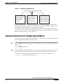
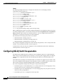
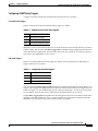
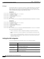
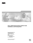
You can find the interface port identifier on the rear of the switch router. It is composed of three parts,
formatted as slot/subslot/interface as depicted in Figure 4-1.
Layer 3 Switching Software Feature and Configuration Guide
4-2
78-6235-04, Cisco IOS Release 12.0(10)W5(18)
Chapter 4
Configuring Interfaces
General Instructions for Configuring Interfaces
Figure 4-1
Interface Port Identifier Format
The slot in which the
interface module or port
adapter is installed.
Slots are numbered
starting at 0.
The subslot in which the
interface module or port
adapter is installed. For a
full-width interface
module, this number is
always 0.
The port or interface
number on the interface
module or port adapter.
Numbering always starts
at 0 and goes from left to
right.
27934
slot number / subslot number / interface number
The interface port identifiers on the Ethernet modules remain the same regardless of whether other
modules are installed or removed. However, when you move an interface module to a different slot, the
first number in the address changes to reflect the new slot number.
You can identify module ports by physically checking the slot/subslot/interface location on the back of
the switch router. You can also use Cisco IOS show commands to display information about a specific
interface, or all the interfaces, in the switch router.
General Instructions for Configuring Interfaces
The following general configuration instructions apply to all interfaces. Begin in global configuration
mode. To configure an interface, follow these steps:
Step 1
Use the configure EXEC command at the privileged EXEC prompt to enter the global configuration
mode.
Router> enable
Router# configure terminal
Router (config)#
Step 2
Enter the interface command, followed by the interface type (for example, Fast Ethernet or Gigabit
Ethernet) and its interface port identifier (see the “Interface Port Identifier” section on page 4-2).
For example, to configure the Gigabit Ethernet port on slot 1, port 1, use this command:
Router(config)# interface gigabitethernet 1/0/1
Layer 3 Switching Software Feature and Configuration Guide
78-6235-04, Cisco IOS Release 12.0(10)W5(18)
4-3
Chapter 4
Configuring Interfaces
About Layer 3 Switching Interfaces
Step 3
Follow each interface command with the interface configuration commands required for your
particular interface.
The commands you enter define the protocols and applications that will run on the interface. The
commands are collected and applied to the interface command until you enter another interface
command, a command that is not an interface configuration command, or you enter end to return to
privileged EXEC mode.
Step 4
Check the status of the configured interface by using the EXEC show commands.
Router# show interface gigabitethernet 1/0/1
GigabitEthernet1/0/1 is up, line protocol is up
Hardware is K1 Gigabit Port, address is 00d0.ba1d.3207 (bia 00d0.ba1d.3207)
MTU 1500 bytes, BW 1000000 Kbit, DLY 10 usec, rely 255/255, load 1/255
Encapsulation ARPA, loopback not set, keepalive set (10 sec)
Full-duplex mode, 1000Mb/s, Auto-negotiation, 1000BaseSX
output flow-control is unsupported, input flow-control is unsupported
ARP type: ARPA, ARP Timeout 04:00:00
About Layer 3 Switching Interfaces
Layer 3 switching supports two different Gigabit Ethernet interfaces, an eight-port module and a
two-port module. This section describes the initial configurations for both interface types.
Tips
Before you configure interfaces, be sure to have the interface network (IP or IPX)
addresses and the corresponding subnet mask information. If you do not have this
information, consult your network administrator.
The Gigabit Ethernet interface modules can be configured as trunk ports, non-trunking ports, routed
ports, or bridged ports. The trunk ports employ 802.1Q encapsulation; Inter-Switch Link (ISL) is not
supported. You can use the Gigabit Ethernet ports as routed interfaces, or you can configure the ports
into a bridge group, which is the recommended configuration.
By configuring as many ports as possible in a bridge group, you can optimize the throughput of your
switch router. You can also ensure that your networks are routed by using integrated routing and
bridging features from Cisco IOS software. For configuration instructions, see the “About Integrated
Routing and Bridging” section on page 6-4.
Between ports on the eight-port Gigabit Ethernet interface module itself, local switching at Layer 2
provides nonblocking performance at wire speed. For ports on this module configured as a bridge group,
Layer 2 traffic is processed at full Gigabit Ethernet rates. For Layer 3 traffic, however, this interface
module provides 2-Gbps routing bandwidth from the switch fabric.
Layer 3 Switching Software Feature and Configuration Guide
4-4
78-6235-04, Cisco IOS Release 12.0(10)W5(18)
Chapter 4
Configuring Interfaces
About Layer 3 Switching Interfaces
Initially Configuring Gigabit Ethernet Interfaces
To configure an IP address and autonegotiation on a Gigabit Ethernet interface, perform the following
steps, beginning in global configuration mode:
Step 1
Command
Purpose
Router(config)# interface gigabitethernet
slot/subslot/interface
Enters Ethernet interface configuration mode to
configure the Gigabit Ethernet interface.
Router(config-if)#
Step 2
Router(config-if)# [no] negotiation auto
Specifies the negotiation mode.
When you set negotiation mode to auto, the
Gigabit Ethernet port attempts to negotiate the
link (that is, both port speed and duplex setting)
with the partner port.
When you set the Gigabit Ethernet interface to no
negotiation auto, the port forces the link up no
matter what the partner port setting is. This brings
up the link with 1000 Mbps and full duplex only.
Step 3
Router(config-if)# ip address ip-address
subnet-mask
Specifies the IP address and IP subnet mask to be
assigned to the Gigabit Ethernet interface.
Step 4
Router(config-if)# exit
Router(config)#
Returns to global configuration mode. Repeat
Steps 1 to 3 to configure another Gigabit Ethernet
interface on this interface module.
Step 5
Router(config)# end
Returns to privileged EXEC mode.
Step 6
Router# copy system:running-config
nvram:startup-config
Saves your configuration changes to NVRAM.
Example
The following example demonstrates initially configuring a Gigabit Ethernet interface with
autonegotiation and an IP address:
Router(config)# interface gigabitethernet 0/0/0
Router(config-if)# negotiation auto
Router(config-if)# ip address 10.1.2.3 255.0.0.0
Router(config-if)# exit
Router(config)# ^Z
C8540-CSR# copy system:running-config nvram:startup-config
About the Enhanced Gigabit Ethernet Interfaces (Catalyst 8540)
The enhanced Gigabit Ethernet interface module provides two Gigabit Ethernet interfaces with built-in
ACL support; no daughter card is required. The POS OC-12c uplink interface module and the ATM
uplink interface module also include a single enhanced Gigabit Ethernet interface. See “Configuring the
POS OC-12c Uplink Interface (Catalyst 8540)” section on page 4-14” and “Configuring the ATM
Uplink Interface (Catalyst 8540)” section on page 4-28.
There is no special configuration required for the enhanced Gigabit Ethernet interfaces other than that
used for other Gigabit Ethernet interfaces.
Layer 3 Switching Software Feature and Configuration Guide
78-6235-04, Cisco IOS Release 12.0(10)W5(18)
4-5
Chapter 4
Configuring Interfaces
About Layer 3 Switching Interfaces
Initially Configuring Fast Ethernet Interfaces
Use the following procedure to assign an IP address to the Fast Ethernet 10BaseT or 100BaseT interface
of your switch router so that it can be recognized as a device on the Ethernet LAN. The Fast Ethernet
interface supports 10-Mbps and 100-Mbps speeds with Cisco 10BaseT and 100BaseT routers, hubs,
switches, and switch routers.
Step 1
Command
Description
Router(config)# interface fastethernet
slot/subslot/interface
Enters Ethernet interface configuration mode to
configure the Fast Ethernet interfaces.
Router(config-if)#
Step 2
Router(config-if)# ip address ip-address
subnet-mask
Specifies the IP address and IP subnet mask to be
assigned to the FastEthernet interface.
Step 3
Router(config-if)# [no] speed [10 | 100 | auto]
Configures the transmission speed for 10 or
100 Mbps, or for autonegotiation (the default). If
you set the speed to auto, you enable
autonegotiation, and the switch router matches
the speed of the partner node.
Step 4
Router(config-if)# [no] duplex [full | half | auto] Configures for full or half duplex. If you set
duplex for auto, the switch router matches the
duplex setting of the partner node.
Step 5
Router(config-if)# end
Returns to privileged EXEC mode.
Router#
Step 6
Router# copy system:running-config
nvram:startup-config
Saves your configuration changes to NVRAM.
Example
The following example demonstrates initially configuring a Fast Ethernet interface with an IP address
and autonegotiated speed and duplex:
Router(config)# interface fastethernet 1/0/0
Router(config-if)# ip address 10.1.2.4 255.0.0.0
Router(config-if)# speed auto
Router(config-if)# duplex auto
Router(config-if)# ^Z
Router# copy system:running-config nvram:startup-config
Verifying the Ethernet Interface Configuration
To verify the settings after you have configured Gigabit Ethernet or Ethernet 10/100 BaseT operation,
use the following commands:
Command
Purpose
show interface gigabitethernet
slot/subslot/interface
Displays the status and global parameters of the
Gigabit Ethernet interface.
show interface fastethernet
slot/subslot/interface
Displays the status and global parameters of the
Fast Ethernet interface.
Layer 3 Switching Software Feature and Configuration Guide
4-6
78-6235-04, Cisco IOS Release 12.0(10)W5(18)
Chapter 4
Configuring Interfaces
About Layer 3 Switching Interfaces
Examples
The following example shows sample output from the show interface gigabitethernet command:
Router# show interface gigabitethernet 0/0/0
GigabitEthernet0/0/0 is administratively down, line protocol is down
Hardware is K1 Gigabit Port, address is 00d0.ba1d.3207 (bia 00d0.ba1d.3207)
Internet address is 10.1.2.3/8
MTU 1500 bytes, BW 1000000 Kbit, DLY 10 usec, rely 255/255, load 1/255
Encapsulation ARPA, loopback not set, keepalive set (10 sec)
Full-duplex mode, 1000Mb/s, Auto-negotiation, 1000BaseSX
output flow-control is unsupported, input flow-control is unsupported
ARP type: ARPA, ARP Timeout 04:00:00
Last input never, output never, output hang never
Last clearing of "show interface" counters never
Queueing strategy: fifo
Output queue 0/40, 0 drops; input queue 0/75, 0 drops
5 minute input rate 0 bits/sec, 0 packets/sec
5 minute output rate 0 bits/sec, 0 packets/sec
0 packets input, 0 bytes, 0 no buffer
Received 0 broadcasts, 0 runts, 0 giants, 0 throttles
0 input errors, 0 CRC, 0 frame, 0 overrun, 0 ignored, 0 abort
0 watchdog, 0 multicast
0 input packets with dribble condition detected
0 packets output, 0 bytes, 0 underruns(0/0/0)
0 output errors, 0 collisions, 0 interface resets
0 babbles, 0 late collision, 0 deferred
0 lost carrier, 0 no carrier
0 output buffer failures, 0 output buffers swapped out
The following example shows sample output from the show interface fastethernet command:
Router# show interface fastethernet 1/0/0
FastEthernet1/0/0 is administratively down, line protocol is down
Hardware is epif_port, address is 0010.073c.050f (bia 0010.073c.050f)
Internet address is 10.1.2.4/8
MTU 1500 bytes, BW 100000 Kbit, DLY 100 usec, rely 255/255, load 1/255
Encapsulation ARPA, loopback not set, keepalive set (10 sec)
Auto-duplex, Auto Speed, 100BaseTX
ARP type: ARPA, ARP Timeout 04:00:00
Last input never, output never, output hang never
Last clearing of "show interface" counters never
Queueing strategy: fifo
Output queue 0/40, 0 drops; input queue 0/75, 0 drops
5 minute input rate 0 bits/sec, 0 packets/sec
5 minute output rate 0 bits/sec, 0 packets/sec
0 packets input, 0 bytes
Received 0 broadcasts, 0 runts, 0 giants, 0 throttles
0 input errors, 0 CRC, 0 frame, 0 overrun, 0 ignored, 0 abort
0 watchdog, 0 multicast
0 input packets with dribble condition detected
0 packets output, 0 bytes, 0 underruns
0 output errors, 0 collisions, 0 interface resets
0 babbles, 0 late collision, 0 deferred
0 lost carrier, 0 no carrier
0 output buffer failures, 0 output buffers swapped out
Layer 3 Switching Software Feature and Configuration Guide
78-6235-04, Cisco IOS Release 12.0(10)W5(18)
4-7
Chapter 4
Configuring Interfaces
About Virtual LANs
About Virtual LANs
Virtual LANs enable network managers to group users logically rather than by physical location. A
virtual LAN (VLAN) is an emulation of a standard LAN that allows data transfer and communication
to occur without the traditional restraints placed on the network. It can also be considered a broadcast
domain set up within a switch. With VLANs, switches can support more than one subnet (or VLAN) on
each switch, and give routers and switches the opportunity to support multiple subnets on a single
physical link. A group of devices on a LAN are configured so that they communicate as if they were
attached to the same LAN segment, when they are actually located on different segments. Layer 3
switching supports up to 255 VLANs per system.
VLANs enable efficient traffic separation and provide excellent bandwidth utilization. VLANs also
alleviate scaling issues by logically segmenting the physical LAN structure into different subnetworks
so that packets are switched only between ports within the same VLAN. This can be very useful for
security, broadcast containment, and accounting.
Layer 3 switching software supports a port-based VLAN on a trunk port, which is a port that carries the
traffic of multiple VLANs. Each frame transmitted on a trunk link is tagged as belonging to only one
VLAN.
Layer 3 switching software supports VLAN frame encapsulation through the Inter-Switch Link (ISL)
protocol and the 802.1Q standard.
Note
The four adjacent ports (such as 0 through 3, or 4 through 7) on a 10/100 interface must
all use the same VLAN encapsulation; that is, either 802.1Q and native, or ISL and native.
Configuring ISL VLAN Encapsulation
ISL is a Cisco protocol for interconnecting multiple switches and maintaining VLAN information as
traffic travels between switches.
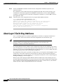
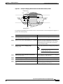
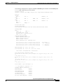
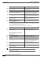
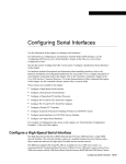
The VLAN configuration example shown in Figure 4-2 depicts the following:
•
Fast Ethernet port 1/0/0 and subinterface 1/0/1.1 on the switch router are in bridge group 1. They
are part of VLAN 50, which uses ISL encapsulation.
•
Fast Ethernet port 3/0/1 and subinterface 1/0/1.2 are in bridge group 2. They are part of VLAN 100,
which uses ISL encapsulation.
•
Fast Ethernet port 1/0/1 is configured as an ISL trunk.
Layer 3 Switching Software Feature and Configuration Guide
4-8
78-6235-04, Cisco IOS Release 12.0(10)W5(18)
Chapter 4
Configuring Interfaces
Configuring ISL VLAN Encapsulation
Figure 4-2
Example of an ISL VLAN Bridging Configuration
Bridge-group 1
1/0/1.1
1/0/0
VLAN 50
encap isl 50
encap isl 100
Campus
switch
router
Campus
switch
router
VLAN 100
1/0/1.2
17489
3/0/1
Bridge-group 2
To configure the Layer 3 VLANs shown in Figure 4-2, perform the following steps, beginning in global
configuration mode:
Step 1
Command
Purpose
Router(config)# interface fastethernet
slot/subslot/interface.subinterface
Enters subinterface configuration mode.
Router(config-subif)#
Step 2
Router(config-subif)# encapsulation isl vlan-id
Specifies ISL encapsulation for the Ethernet
frames sent from this subinterface with a
header that maintains the specified VLAN ID
between network nodes.
Step 3
Router(config-subif)# bridge-group bridge-group
Assigns the subinterface a bridge group
number.
Note
Step 4
Router(config-subif)# interface fastethernet
slot/subslot/interface
When you are configuring VLAN
routing, skip this step.
Enters interface configuration mode to
configure the Fast Ethernet main interface.
Router(config-if)#
Step 5
Router(config-if)# bridge-group bridge-group
Assigns the main interface to the bridge
group.
Step 6
Router(config-if)# exit
Returns to global configuration mode.
Router(config)#
Step 7
Router(config)# bridge bridge-group protocol ieee
Specifies that the bridge group will use the
IEEE Ethernet Spanning Tree Protocol.
Layer 3 Switching Software Feature and Configuration Guide
78-6235-04, Cisco IOS Release 12.0(10)W5(18)
4-9
Chapter 4
Configuring Interfaces
Configuring 802.1Q VLAN Encapsulation
Example
The following example shows how to configure the interfaces for VLAN bridging with ISL
encapsulation shown in Figure 4-2:
Router(config)# interface fastethernet 1/0/1.1
Router(config-subif)# encap isl 50
Router(config-subif)# bridge-group 1
Router(config-subif)# interface fastethernet 1/0/0
Router(config-if)# bridge-group 1
Router(config-if)# exit
Router(config)# bridge 1 protocol ieee
Router(config)# interface fastethernet 1/0/1.2
Router(config-subif)# encap isl 100
Router(config-subif)# bridge-group 2
Router(config-subif)# interface fastethernet 3/0/1
Router(config-subif)# bridge-group 2
Router(config-subif)# exit
Router(config)# bridge 2 protocol ieee
Router(config)# exit
Router# copy system:running-config nvram:startup-config
When configuring ISL with IP, you cannot configure IP addresses on a subinterface unless the VLANs
are already configured (that is, you must have already entered the encapsulation isl or encapsulation
dot1q command). That is not the case with IPX, however—you can configure IPX networks on a
subinterface even when the VLANs have not been configured.
The maximum VLAN bridge group values are as follows:
•
Maximum number of bridge groups: 64
•
Maximum number of interfaces per bridge group: 128
•
Maximum number of subinterfaces per system: 255
For a complete configuration example for VLANs with ISL encapsulation, see the “Catalyst 8540 CSR
with ISL, VLAN, and BVI with GEC” section on page C-1.
To monitor the VLANs once they are configured, use the commands described in the “Monitoring
VLAN Operation” section on page 4-12.
Configuring 802.1Q VLAN Encapsulation
The IEEE 802.1Q standard provides a method for secure bridging of data across a shared backbone.
IEEE 802.1Q VLAN encapsulation uses an internal, or one level, packet tagging scheme to multiplex
VLANs across a single physical link, while maintaining strict adherence to the individual VLAN
domains.
On an IEEE 802.1Q trunk port, all transmitted and received frames are tagged except for those on the
one VLAN configured as the PVID (port VLAN identifier) or native VLAN for the port. Frames on the
native VLAN are always transmitted untagged and are normally received untagged.
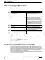
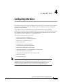
The VLAN configuration example shown in Figure 4-3 depicts the following:
•
Fast Ethernet ports 1/0/0 and subinterface 1/0/1.1 on the switch router are in bridge group 1. They
are part of native VLAN 1, which uses 802.1Q encapsulation.
•
Fast Ethernet port 3/0/1 and subinterface 1/0/1.2 are in bridge group 2. They are part of VLAN 100,
which uses 802.1Q encapsulation.
•
Fast Ethernet port 1/0/1 is configured as an 802.1Q trunk.
Layer 3 Switching Software Feature and Configuration Guide
4-10
78-6235-04, Cisco IOS Release 12.0(10)W5(18)
Chapter 4
Configuring Interfaces
Configuring 802.1Q VLAN Encapsulation
Figure 4-3
Example of Bridging Between Native and Non-Native 802.1Q VLANs
Bridge-group 1
1/0/1.1
1/0/0
Native VLAN 1
encap dot1q 1 native
encap dot1q 100
Campus
switch
router
Campus
switch
router
Non-native VLAN 100
1/0/1.2
28089
3/0/1
Bridge-group 2
To configure the bridging between native VLAN 1 and non-native VLAN 100 depicted in Figure 4-3,
perform the following steps:
Command
Purpose
Step 1
Router(config)# interface fastethernet
slot/subslot/interface.subinterface
Enters subinterface configuration mode.
Step 2
Router(config-subif)# encap dot1q vlan-id native Specifies 802.1Q encapsulation for Ethernet
frames sent from the subinterface with a header
that maintains the specified native VLAN ID
between network nodes.
Step 3
Router(config-subif)# bridge-group
bridge-group
Assigns the subinterface a bridge group number.
Note
When you are configuring VLAN
routing, skip this step.
Step 4
Router(config-subif)# interface fastethernet
slot/subslot/interface
Enters interface configuration mode to configure
the Fast Ethernet main interface.
Step 5
Router(config-if)# bridge-group bridge-group
Assigns the main interface to the bridge group.
Step 6
Router(config-if)# exit
Returns to global configuration mode.
Step 7
Router(config)# bridge bridge-group protocol
ieee
Specifies that the bridge group will use the IEEE
Ethernet Spanning Tree Protocol.
Layer 3 Switching Software Feature and Configuration Guide
78-6235-04, Cisco IOS Release 12.0(10)W5(18)
4-11
Chapter 4
Configuring Interfaces
Monitoring VLAN Operation
Example
The following example shows how to configure the bridging between native and non-native 802.1Q
VLANs shown in Figure 4-3:
Router(config)# interface fastethernet 1/0/1.1
Router(config-subif)# encap dot1q 1 native
Router(config-subif)# bridge-group 1
Router(config-subif)# interface fastethernet 1/0/0
Router(config-if)# bridge-group 1
Router(config-if)# exit
Router(config)# bridge 1 protocol ieee
Router(config)# interface fastethernet 1/0/1.2
Router(config-subif)# encap dot1q 100
Router(config-subif)# bridge-group 2
Router(config-subif)# interface fastethernet 3/0/1
Router(config-subif)# bridge-group 2
Router(config-subif)# exit
Router(config)# bridge 2 protocol ieee
Router(config)# exit
Router# copy system:running-config nvram:startup-config
Monitoring VLAN Operation
Once the VLANs are configured on the switch router, you can monitor their operation using the
following commands:
Command
Purpose
show vlan vlan-id
Displays information on all configured VLANs or on a specific
VLAN (by VLAN ID number).
clear vlan vlan-id
Clears the counters for all VLANs, when the VLAN ID is not
specified.
debug vlan packet
Displays contents of the packets sent to and exiting from the route
processor.
To configure encapsulation over the EtherChannel, see the “About Encapsulation over EtherChannel”
section on page 7-6.
About Packet over SONET (Catalyst 8540)
Synchronous Optical Network (SONET) is an octet-synchronous multiplex scheme that defines a family
of standard rates and formats. Optical specifications are defined for single-mode fiber and multimode
fiber. The transmission rates are integral multiples of 51.840 Mbps. For example, the POS OC-12c
uplink interface provides 622.080 Mbps over single-mode optical fiber.
POS provides for the serial transmission of data over SONET frames using either High-Level Data Link
Control (HDLC) protocol (the default) or Point-to-Point Protocol (PPP) encapsulation. On serial
interfaces, Cisco’s implementation provides error detection and synchronous framing functions of
traditional HDLC without the windowing or retransmission that are found in traditional HDLC.
Layer 3 Switching Software Feature and Configuration Guide
4-12
78-6235-04, Cisco IOS Release 12.0(10)W5(18)
Chapter 4
Configuring Interfaces
About the POS OC-12c Uplink Interface
Because SONET/SDH (Synchronous Digital Hierarchy) is by definition a point-to-point circuit, PPP is
well suited for use over SONET links. The octet stream is mapped into the SONET/SDH synchronous
payload envelope (SPE) in accordance with RFC 2615, “PPP over SONET/SDH,” and RFC 2615, “PPP
in HDLC-like Framing.” Octet boundaries are aligned with the SPE octet boundaries, and the PPP
frames are located by row within the SPE payload. Because frames are variable in length, the frames
can cross SPE boundaries. Using this scheme, multiprotocol data can be encapsulated and transported
directly into SONET frames without relying on ATM to provide Layer 2 capability (for example, in IP
over ATM over SONET).
About the POS OC-12c Uplink Interface
POS technology is ideally suited for networks that are built for providing Internet or IP data. It provides
superior bandwidth utilization and efficiency over other transport methods. For expensive WAN links,
POS can provide as much as 25 to 30 percent higher throughput than ATM-based networks.
Transporting frames directly into the SONET/SDH payload eliminates the overhead required in ATM
cell header, IP over ATM encapsulation, and segmentation and reassembly (SAR) functionality.
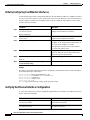
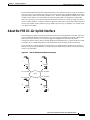
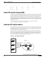
Figure 4-4 shows a typical application of the POS OC-12c uplink interface module in an enterprise
setting. Here the enterprise backbone is comprised of POS links among Catalyst 8540 campus switch
routers in each building.
Figure 4-4
POS for Enterprise Backbone Connectivity
OC-12c POS
OC-12c POS
POS
OC-12c POS
30746
OC-12c POS
Layer 3 Switching Software Feature and Configuration Guide
78-6235-04, Cisco IOS Release 12.0(10)W5(18)
4-13
Chapter 4
Configuring Interfaces
Configuring the POS OC-12c Uplink Interface (Catalyst 8540)
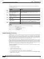
Figure 4-5 shows an example of a service provider application of the POS OC-12c uplink interface
module. Here traffic is aggregated from Catalyst 8500 CSRs over POS OC-12c interfaces to Cisco
12000 GSRs. POS OC-48 interfaces on the Cisco 12000 gigabit switch routers then provide the uplinks
to the Internet backbone.
Figure 4-5
POS for Aggregated Traffic Uplink to Internet
Internet
Backbone
OC-48c/STM-16
OC-12c/STM-4 POS
Cisco 12000 GSRs
30747
OC-12c/STM-4 POS
Catalyst 8540s
Configuring the POS OC-12c Uplink Interface (Catalyst 8540)
This section describes the default configuration of the POS OC-12c uplink interface, initial
configurations you should perform for a newly installed interface, and optional configurations you can
do to customize the interfaces to the requirements of your network.
Note
The POS OC-12c uplink interface module consists of one OC-12c port and one enhanced
Gigabit Ethernet port. For instructions on configuring the Gigabit Ethernet interface, see
the “About the Enhanced Gigabit Ethernet Interfaces (Catalyst 8540)” section on page 4-5.
Layer 3 Switching Software Feature and Configuration Guide
4-14
78-6235-04, Cisco IOS Release 12.0(10)W5(18)
Chapter 4
Configuring Interfaces
Configuring the POS OC-12c Uplink Interface (Catalyst 8540)
Default Configuration
Table 4-1 shows the default configuration of an enabled POS OC-12c uplink interface. To change any
of these values, see the instructions in the following sections, “Initially Configuring the POS Interface”
and “Customizing the Configuration.”
Table 4-1
POS OC-12c Uplink Interface Default Configuration Values
Parameter
Configuration Command
Default Value
Keepalive
[no] keepalive seconds
Keepalives enabled, 10 seconds
Encapsulation
encapsulation {hdlc | ppp}
HDLC
Cisco Discovery Protocol (CDP) [no] cdp enable
CDP enabled
Maximum transmission unit
(MTU)
[no] mtu bytes
4470 bytes
Framing
pos framing {sdh | sonet}
SONET OC-12c
Bandwidth
[no] bandwidth kbps
622000 kbps (not configurable)
SONET overhead
pos flag {c2 value | j0 value |
s1s0 value}
c2 (path signal byte) set to 0xcf;
j0 (section trace byte) set to
0xcc;
s1s0 (bit s1 and s0 of H1) set to 0
Loop internal
[no] loopback {internal | line} No loopback
POS SPE scrambling
[no] pos scramble-atm
POS SPE scrambling enabled
Cyclic redundancy check
crc {16 | 32}
32
Clock source
clock source {internal | line}
Line
Initially Configuring the POS Interface
You should configure the following properties for a newly installed POS OC-12c uplink interface:
•
IP routing
•
IP address
•
Encapsulation type
•
Clock source
You should also configure the following properties to match those of the interface at the other end:
•
Keepalive messages
•
Cisco Discovery Protocol (CDP)
•
Cyclic redundancy check (CRC)
•
Scrambling
•
Encapsulation type
Layer 3 Switching Software Feature and Configuration Guide
78-6235-04, Cisco IOS Release 12.0(10)W5(18)
4-15
Chapter 4
Configuring Interfaces
Configuring the POS OC-12c Uplink Interface (Catalyst 8540)
To initially configure the POS OC-12c uplink interface, perform the following steps, beginning in
global configuration mode:
Command
Purpose
Step 1
Router(config)# ip routing
Enables IP routing.
Step 2
Router(config)# interface pos
slot/subslot/interface
Enters interface configuration mode and specifies the POS
interface to configure.
Router(config-if)#
Step 3
Router(config-if)# ip address
ip-address subnet-mask
Step 4
Router(config-if)# encapsulation Specifies the encapsulation type.
{hdlc | ppp}
Step 5
Router(config-if)# clock source
{line | internal}
Specifies the clock source for the interface. When clocking is
derived from the received clock, line (the default) is used. When
no line clocking source is available, internal is used.
Step 6
Router(config-if)# no shutdown
Enables the interface with the previous configurations.
Assigns an IP address and subnet mask to the interface.
Example
The following configuration is an example of the tasks in the preceding table:
Router(config)# interface pos 1/0/0
Router(config-if)# ip address 10.1.2.3 255.0.0.0
Router(config-if)# encapsulation ppp
Router(config-if)# clock source line
Router(config-if)# no shutdown
Automatic Reverting of Clock Source
If your system clock source is set to line clock, it uses the recovered received clock to transmit. Under
some conditions, the received clock is not reliable because of severe degradation of the signal quality.
Because your system software monitors SF (signal failure), it knows when there is severe degradation
in the signal quality and resorts to using the internal clock temporarily. Once the conditions that caused
the signal quality to deteriorate clear, your system reverts to the line clock.
When two POS interface modules are connected and configured with the default line clock, the signal
quality can degrade over time and both POS interfaces revert to the internal clock. As soon as the signal
quality improves, both POS interfaces revert to using the line clock. This cycle repeats itself causing
the line protocol on both interfaces to toggle. You can prevent this situation by configuring one end of
the connection with the default line clock and the other with the internal clock.
In addition, degradation in the signal quality causes an automatic reverting of the clock source under
the following conditions:
•
SLOS (section loss of signal)
•
SLOF (section loss of frame)
•
AIS-L (line alarm indication signal)
•
SF (signal failure) due to B2 error rate crossing the SF threshold value
•
SF (signal failure) due to B3 error rate crossing the SF threshold value when the pos delay triggers
path command is configured
Layer 3 Switching Software Feature and Configuration Guide
4-16
78-6235-04, Cisco IOS Release 12.0(10)W5(18)
Chapter 4
Configuring Interfaces
Configuring the POS OC-12c Uplink Interface (Catalyst 8540)
Additional Configurations
To configure additional properties to match those of the interface at the far end, perform the following
steps, beginning in global configuration mode:
Command
Purpose
Step 1
Router(config-if)# no keepalive
Turns off keepalive messages. Keepalive messages, though not
required, are recommended.
Step 2
Router(config-if)# no cdp enable Turns off CDP, which is not required.
Step 3
Router(config-if)# crc {16 | 32}
Note
The above steps apply both to the POS OC-12c uplink interface on the switch router and
to the interface to which it connects at the far end.
Sets the CRC value. If the device to which the POS module is
connected does not support the default CRC value of 32, set both
devices to use a value of 16.
Customizing the Configuration
This section describe how to customize the configuration of the POS OC-12c uplink interface to match
your network environment.
Setting the MTU Size
To set the maximum transmission unit (MTU), perform the following steps, beginning in global
configuration mode:
Step 1
Command
Purpose
Router(config)# interface pos
slot/subslot/interface
Enters interface configuration mode and specifies the POS
interface to configure.
Router(config-if)#
Step 2
Router(config-if)# mtu bytes
Note
The POS OC-12c uplink interface supports IP unicast and IP multicast fragmentation. For
IP unicast fragmentation, the packet must ingress on a POS interface and egress on any
interface. For IP multicast fragmentation, IP multicast data packets greater than
1500 bytes are fragmented to 1500 bytes on the ingress POS interface before being
switched to other members in the multicast group. All the members in the multicast group
must have a MTU equal to or greater than 1500 bytes.
Configures the MTU size up to a maximum of 9188 bytes. Default
MTU size is 4470 bytes.
Layer 3 Switching Software Feature and Configuration Guide
78-6235-04, Cisco IOS Release 12.0(10)W5(18)
4-17
Chapter 4
Configuring Interfaces
Configuring the POS OC-12c Uplink Interface (Catalyst 8540)
Configuring Framing
The default framing mode for the POS OC-12c uplink interface is SONET STS-12c. You can also
configure the interface for SDH STM-4, which is more widely used in Europe. To configure the framing
mode on the POS OC-12c uplink interface, perform the following steps, beginning in global
configuration mode:
Step 1
Command
Purpose
Router(config)# interface pos
slot/subslot/interface
Enters interface configuration mode and specifies the POS
interface to configure.
Router(config-if)#
Step 2
Router(config-if)# pos framing
{sdh | sonet}
Configures the framing mode.
POS framing defaults to SONET. The following default values
are used for SONET.
•
s1s0 default value is 0.
•
J1 defaults set to host name, interface name, and IP address.
The following default values are used for SDH framing:
Step 3
Router(config-if)# no shutdown
•
s1s0 default value is 2.
•
J1 is the path trace string. Its default setting is empty and is
not configurable.
Enables the interface with the previous configuration.
Configuring SONET Overhead
You can set the SONET overhead bytes in the frame header to meet a specific standards requirement or
to ensure interoperability of the POS OC-12c uplink interface with another vendor's equipment. To
configure the SONET overhead, perform the following steps, beginning in global configuration mode:
Step 1
Command
Purpose
Router(config)# interface pos
slot/subslot/interface
Enters interface configuration mode and specifies the POS
interface to configure.
Router(config-if)#
Step 2
Router(config-if)# pos flag {c2
value | j0 value | sls0 value}
Configures the SONET overhead bytes. c2 is a path signal
identifier, j0 is the section trace byte, and sls0 is the bit s1 and s0
of the H1 payload pointer byte.
Step 3
Router(config-if)# no shutdown
Enables the interface with the previous configuration.
Layer 3 Switching Software Feature and Configuration Guide
4-18
78-6235-04, Cisco IOS Release 12.0(10)W5(18)
Chapter 4
Configuring Interfaces
Configuring the POS OC-12c Uplink Interface (Catalyst 8540)
The value of the c2 byte is determined as follows:
•
If the value of the c2 byte has not been explicitly configured with the pos flag command, the
SONET framer sends the following values:
– For Cisco HDLC encapsulation with or without SPE scrambling: 0xCF
– For PPP encapsulation with scrambling: 0x16 (RFC 2615)
– For PPP encapsulation without scrambling: 0xCF (RFC 2615)
•
If the value of the c2 byte has been explicitly configured with the pos flag command, the configured
value is sent regardless of the encapsulation method.
The value of the s1s0 bits is determined as follows:
•
If the value of the s1s0 bits have not been explicitly configured with the pos flag command, the
SONET framer sends the following values:
– For SONET framing, the default value is 0.
– For SDH framing, the default value is 2.
•
If the value of the s1s0 bits have been explicitly configured with the pos flag command, the
configured value is used regardless of the framing.
Configuring POS SPE Scrambling
SONET payload scrambling applies a self-synchronous scrambler of polynomial X**43+1 to the
synchronous payload envelope (SPE) of the interface to ensure sufficient bit transition density. Both
ends of the connection must use the same scrambling algorithm.
To configure POS SPE scrambling, perform the following steps, beginning in global configuration
mode:
Step 1
Command
Purpose
Router(config)# interface pos
slot/subslot/interface
Enters interface configuration mode and specifies the POS
interface to configure.
Router(config-if)#
Step 2
Router(config-if)# no pos
scramble-atm
Disables payload scrambling on the interface. Payload
scrambling is on by default.
Step 3
Router(config-if)# no shutdown
Enables the interface with the previous configuration.
Layer 3 Switching Software Feature and Configuration Guide
78-6235-04, Cisco IOS Release 12.0(10)W5(18)
4-19
Chapter 4
Configuring Interfaces
Configuring the POS OC-12c Uplink Interface (Catalyst 8540)
Configuring SONET Alarms
The OC-12c POS uplink interface supports SONET alarm monitoring. To configure alarm monitoring,
perform the following steps, beginning in global configuration mode:
Step 1
Command
Purpose
Router(config)# interface pos
slot/subslot/interface
Enters interface configuration mode and specifies the POS
interface to configure.
Router(config-if)#
Step 2
Router(config-if)# pos report
{b1-tca | b2-tca | b3-tca | lais |
lrdi | pais | plop | prdi | plm-p |
sd-ber | sf-ber | slof | slos |
uneq-p}
Permits console logging of selected SONET alarms.
The alarms are as follows:
•
b1-tca (B1 bit error rate [BER] threshold crossing alarm)
•
b2-tca (B2 BER threshold crossing alarm)
•
b3-tca (B3 BER threshold crossing alarm)
•
lais (line alarm indication signal)
•
lrdi (line remote defect indication)
•
pais (path alarm indication signal)
•
plop (path loss of pointer)
•
prdi (path remote defect indication)
•
plm-p (payload label, C2 mismatch alarm)
•
sd-ber (LBIP BER in excess of threshold)
•
sf-ber (signal failure BER)
•
slof (section loss of frame)
•
slos (section loss of signal), uneq-p (path unequipped C2
alarm).
The b1-tca, b2-tca, b3-tca, sf-ber, slof, and slos errors are
reported by default.
Step 3
Router(config-if)# pos threshold Sets the BER threshold values of the specified alarms. Default
{b1-tca | b2-tca | b3-tca | sd-ber | values are 6 for b1-tca, b2-tca, b3-tca, and sd-ber; 3 for sf-ber.
sf-ber} rate
Step 4
Router(config-if)# pos ais-shut
Sends a line alarm indication signal (AIS-L) to the other end of
the link after a shutdown command has been issued to the
specified POS interface. By default, the AIS-L is not sent to the
other end of the link.
You can stop transmitting the AIS-L by issuing either the
no shutdown or the no pos ais-shut commands.
To determine which alarms are reported on the POS interface, and to display the BER thresholds, use
the show controllers pos command, as described in the next section, “Verifying the POS
Configuration” section on page 4-22. For a detailed description of the pos report and pos threshold
commands, refer to the Cisco IOS Interface Command Reference publication.
Layer 3 Switching Software Feature and Configuration Guide
4-20
78-6235-04, Cisco IOS Release 12.0(10)W5(18)
Chapter 4
Configuring Interfaces
Configuring the POS OC-12c Uplink Interface (Catalyst 8540)
Configuring SONET Delay Triggers
A trigger is an alarm, which when asserted causes the line protocol to go down.
Line and Section Triggers
Table 4-2 lists the line and section alarms that are triggers by default:
Table 4-2
Default Line and Section Alarm Triggers
Alarm Description
SLOS
Section loss of signal
SLOF
Section loss of frame
AIS-L Line alarm indication signal
When one or more of the alarms in Table 4-2 are asserted, the line protocol of the interface goes down
without a delay. You can issue a pos delay triggers line command to delay triggering the line protocol
of the interface from going down. You can set the delay from 50 to 10000 ms. If you do not specify a
time interval, the default delay is set to 100 ms.
Path Level Triggers
Table 4-3 lists path alarms that are not triggers by default. You can configure these path alarms as
triggers and also specify a delay.
Table 4-3
Configurable Path Alarm Triggers
Alarm
Description
AIS-P
Path alarm indication signal
RDI-P
Path remote defect indication
LOP-P
Path loss of pointer
You can issue the pos delay triggers path command to configure the path alarms listed in Table 4-3 as
triggers. These triggers will bring down the line protocol of the interface. When you configure the path
alarms as triggers, you can simultaneously specify a delay for the triggers. You can set the delay from
50 to 10000 ms. If you do not specify a time interval, the default delay is set to 100 ms.
The pos delay triggers path configuration can also bring the line protocol of the interface down when
the higher of the B2 and B3 error rates is compared with the SF (signal failure) threshold. If the SF
threshold is crossed, then the line protocol of the interface goes down.
Layer 3 Switching Software Feature and Configuration Guide
78-6235-04, Cisco IOS Release 12.0(10)W5(18)
4-21
Chapter 4
Configuring Interfaces
Configuring the POS OC-12c Uplink Interface (Catalyst 8540)
To configure a delay in triggering the line protocol of the interface from going down, perform the
following steps beginning in global configuration mode:
Step 1
Command
Purpose
Router(config)# interface pos
slot/subslot/interface
Enters interface configuration mode and specifies the POS
interface to configure.
Router(config-if)#
Step 2
Router(config-if)# pos report
{lais | pais | plop| prdi | slof |
slos}
Permits console logging of selected SONET alarms.
The alarms are as follows:
•
lais (line alarm indication signal)
•
pais (path alarm indication signal)
•
plop (path loss of pointer)
•
prdi (path remote defect indication)
•
slof (section loss of frame)
•
slos (section loss of signal)
The slof and slos errors are reported by default.
Step 3
Router(config-if)# pos delay
Delays triggering the line protocol of the interface from going
triggers {line | path} millisecond down. Delay can be set from 50 to 10000 ms. If no time intervals
are specified, the default delay is set to 100 ms.
Verifying the POS Configuration
To verify the configuration of the POS OC-12c uplink interface, use the following commands:
Command
Purpose
show interfaces pos [slot/subslot/interface]
Displays detailed information about the POS
interface.
show protocols pos [slot/subslot/interface]
Displays status information for the active network
protocols
show controllers pos [slot/subslot/interface]
Displays clock source, SONET alarms and error
rates, and register values to assist in
troubleshooting.
Layer 3 Switching Software Feature and Configuration Guide
4-22
78-6235-04, Cisco IOS Release 12.0(10)W5(18)
Chapter 4
Configuring Interfaces
Configuring the POS OC-12c Uplink Interface (Catalyst 8540)
Examples
The following example shows output for the show interfaces pos command:
Router# show interfaces pos 1/0/0
POS1/0/0 is up, line protocol is down
Hardware is Packet Over SONET
Internet address is 10.1.2.3/8
MTU 4470 bytes, BW 622000 Kbit, DLY 100 usec, rely 255/255, load 1/255
Encapsulation PPP, crc 32, loopback not set, keepalive not set
Scramble enabled
LCP REQsent
Closed: CDPCP
Last input never, output never, output hang never
Last clearing of "show interface" counters never
Queueing strategy: fifo
Output queue 0/40, 0 drops; input queue 0/75, 0 drops
5 minute input rate 0 bits/sec, 0 packets/sec
5 minute output rate 0 bits/sec, 0 packets/sec
0 packets input, 0 bytes, 0 no buffer
Received 0 broadcasts, 0 runts, 0 giants, 0 throttles
0 parity
0 input errors, 0 CRC, 0 frame, 0 overrun, 0 ignored, 0 abort
0 packets output, 480 bytes, 0 underruns
0 output errors, 0 applique, 5 interface resets
0 output buffer failures, 0 output buffers swapped out
0 carrier transitions
The following example shows output for the show protocols pos command:
Router# show protocols pos 1/0/0
POS1/0/0 is up, line protocol is down
Internet address is 10.1.2.3/8
Layer 3 Switching Software Feature and Configuration Guide
78-6235-04, Cisco IOS Release 12.0(10)W5(18)
4-23
Chapter 4
Configuring Interfaces
Configuring the POS OC-12c Uplink Interface (Catalyst 8540)
The following example shows output for the show controllers pos command:
Router# show controllers pos 2/0/0
Interface POS2/0/0
Hardware is Packet Over SONET, One-port OC12, Single Mode Intermediate Reach
POS2/0/0
SECTION
LOF = 1
LINE
AIS = 0
PATH
AIS = 0
LOP = 1
PLM-P = 1
LOS = 0
BIP(B1) = 96
RDI = 1
FEBE = 265
BIP(B2) = 1170
RDI = 1
FEBE = 78
BIP(B3) = 51
UNEQ-P = 0
Active Alarms: None
Active Defects:None
Alarm reporting enabled for:SF SLOS SLOF B1-TCA B2-TCA PLOP B3-TCA
Framing:SONET
APS
COAPS = 25
PSBF = 1
State:PSBF_state = False
Rx(K1/K2):00/00 Tx(K1/K2):00/00
S1S0 = 00, C2 = 0x16
PATH TRACE BUFFER:UNSTABLE
Remote hostname :acl-traffi0.
Remote interface:POS9/0/0
Remote IP addr :0.0.0.0
Remote Rx(K1/K2):00/00 Tx(K1/K2):00/00
BER thresholds: SF = 10e-3
TCA thresholds: B1 = 10e-6
SD = 10e-6
B2 = 10e-6
Clock source: Configured:line
B3 = 10e-6
Current:line
Last valid pointer from H1-H2: 0x20A
Layer 3 Switching Software Feature and Configuration Guide
4-24
78-6235-04, Cisco IOS Release 12.0(10)W5(18)
Chapter 4
Configuring Interfaces
Configuring the POS OC-12c Uplink Interface (Catalyst 8540)
The following example shows output for the show controllers pos command with the detail option:
Router# show controller pos 2/0/0 detail
Interface POS2/0/0
Hardware is Packet Over SONET, One-port OC12, Single Mode Intermediate Reach
POS2/0/0
SECTION
LOF = 1
LINE
AIS = 0
PATH
AIS = 0
LOP = 1
PLM-P = 1
LOS = 0
BIP(B1) = 96
RDI = 1
FEBE = 265
BIP(B2) = 1170
RDI = 1
FEBE = 78
BIP(B3) = 51
UNEQ-P = 0
Active Alarms: None
Active Defects:None
Alarm reporting enabled for:SF SLOS SLOF B1-TCA B2-TCA PLOP B3-TCA
Framing:SONET
APS
COAPS = 25
PSBF = 1
State:PSBF_state = False
Rx(K1/K2):00/00 Tx(K1/K2):00/00
S1S0 = 00, C2 = 0x16
PATH TRACE BUFFER:STABLE
Remote hostname :acl-traffic
Remote interface:POS9/0/0
Remote IP addr :0.0.0.0
Remote Rx(K1/K2):00/00 Tx(K1/K2):00/00
61
00
00
00
63
00
00
00
6C
2F
00
00
2D
30
00
00
74
00
00
00
72
00
00
00
61
00
30
30
66
00
2E
30
BER thresholds: SF = 10e-3
TCA thresholds: B1 = 10e-6
66
50
30
30
69
4F
2E
30
63
53
30
30
00
39
2E
30
SD = 10e-6
B2 = 10e-6
Clock source: Configured:line
00
2F
30
30
00
30
00
30
00
2F
00
0D
00
30
00
0A
acl-traffic.....
../0....POS9/0/0
......0.0.0.0...
......00000000..
B3 = 10e-6
Current:line
Last valid pointer from H1-H2: 0x20A
B1:set 564, clr 124, ber 0, err 0, lk<1eps 0/0, lk_eps 95, dly 0, set 1, clr
10
, A 0, Rd 0, R 1, D 1
B2:set 564, clr 124, ber 0, err 0, lk<1eps 0/0, lk_eps 0, dly 0, set 1, clr
10,
A 0, Rd 0, R 1, D 1
B3:set 564, clr 124, ber 0, err 0, lk<1eps 0/0, lk_eps 50, dly 0, set 1, clr
10
, A 0, Rd 0, R 1, D 1
Total number of port interrupts = 33
----- POS module IO registers ----Starting address @0xBC280000
FPGA Revision
= 0x0001
Reset Register
= 0x0003
Tx/Rx LED Register
= 0x0000
Alarm LED Register
= 0x0000
CD LED Register
= 0x0000
PLL Control Register
= 0x0003
Tx Clock Config Register = 0x0000
Layer 3 Switching Software Feature and Configuration Guide
78-6235-04, Cisco IOS Release 12.0(10)W5(18)
4-25
Chapter 4
Configuring Interfaces
Configuring the POS OC-12c Uplink Interface (Catalyst 8540)
Interrupt Mask Register
= 0x0001
Parity Error Register
= 0x0000
Scratch Register
= 0x80000000
Debug Register
= 0x0000
CRC32 enabled, PPP enc, Diag control reg 1:0x0
GPIO port:loop timed
GPIO port:no loop
----- Skystone Performance Monitor Counters ----rpp_pm1
rpp_pm2
rpp_pm3
rpp_pm4
rpp_pm5
rpp_pm6
rpp_pm7
(packet)
(bytes )
(crc
)
(runts )
(giants)
(ignore)
(abort )
=
=
=
=
=
=
=
1154
36225
105
67
0
142
0
tpp_pm1 (packet) = 554
tpp_pm2 (bytes ) = 15127
tpp_pm3 (stuff ) = 41
tpp_pm4 (underflow) = 0
tpp_pm5 (ext er) = 0
tpp_pm6 (1 byte) = 0
----- Skystone Registers ----line_cfg_cntrl=0x3
MIF_cntrl_u=0x0
gpio_port_u=0x0
gpio_port_l=0x40
gpio_port_cntrl_u=0xF
gpio_port_cntrl_l=0xFF
hi_prio_intr_mask_u=0x0
hi_prio_intr_mask_l=0x0
tor_ram_c2=0x16
rpp_cntrl_1=0x3F
rpp_max_pkt_len_u=0x11
rpp_max_pkt_len_l=0xF4
rpp_min_pkt_len=0x3
rpp_cntrl_2=0x3
tpp_cntrl_1=0x40
tpog_cntrl=0x22
tpp_inter_pkt_u=0x0
tpp_inter_pkt_l=0x0
ttog_ovrhd_src_1=0x80
tpog_cntrl=0x22
sys_intf_cntrl_1=0x5
sys_intf_cntrl_2=0x0
hi_prio_intr_status_u=0x0
hi_prio_intr_status_l=0x0
lo_prio_intr_mask=0xFF
lo_prio_intr_status=0x0
----- XPIF SLICER Registers ----SMDR 0xFF78 SSTR 0x1200 SSMR 0x4002 EVER 0x3001
SIMR 0x0000 MBXW 0x0000 MBXR 0x0000 SPER 0xF000
Xpif
MR1
MR6
MR11
MR16
Counters:
21723
0
1152
0
MR2
MR7
MR12
MR17
0
0
0
0
MR3
MR8
MR13
MR18
0
0
0
104
MR4
MR9
MR14
MR19
0
0
1155
0
MR5
MR10
MR15
MR20
3
0
0
0
MR21 0
Layer 3 Switching Software Feature and Configuration Guide
4-26
78-6235-04, Cisco IOS Release 12.0(10)W5(18)
Chapter 4
Configuring Interfaces
About ATM Uplinks (Catalyst 8540)
SR1
72036
SR2
18806
SR3
0
SR4
0
SR5
0
MT1
MT6
ST1
MRXS
15143
0
0
262160
MT2
MT7
ST2
MTXS
0
0
0
16
MT3
MT8
0
0
MT4
MT9
0
0
MT5
6
SRXS 3
STXS 0
About ATM Uplinks (Catalyst 8540)
ATM uses cell-switching and multiplexing technology that combines the benefits of circuit switching
(constant transmission delay and guaranteed capacity) with those of packet switching (flexibility and
efficiency for intermittent traffic). ATM is a common network technology for enterprise backbones,
MANs, and WANs. By using an ATM uplink, Layer 3 traffic can be routed over an ATM network. The
ATM uplink facilitates this by segmenting packet data into fixed-size cells at the transmitting end and
reassembling them into packets at the receiving end. This conversion process is defined by the ATM
adaptation layer (AAL).
For further information about ATM and its implementation on the Catalyst 8540 MSR and
Catalyst 8510 MSR, refer to the Guide to ATM Technology.
About the ATM Uplink Interface
The ATM uplink interface allows the Catalyst 8540 switch router to be deployed as part of an existing
network where a router with an ATM interface would otherwise have been utilized. Additionally, the
ATM uplink interface allows a Catalyst 8540 deployed as a Layer 3 switch (CSR) to be connected to a
Catalyst 8540 deployed as an ATM switch (MSR).
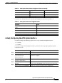
Figure 4-6 shows an example application of the ATM uplink in which traffic from a LAN switch is
aggregated at the Catalyst 8540 CSR and then passed to the ATM network over the ATM uplink. The
Layer 3 enabled ATM uplink supports RFC 1483 (Multiprotocol Encapsulation over ATM), which
provides for the mapping of Layer 3 addresses to ATM virtual circuits, and traffic shaping. Refer to the
Guide to ATM Technology for additional information on RFC 1483.
Figure 4-6
Layer 3 Traffic with ATM Uplink
Wiring closet
ATM uplink
Catalyst 8540 CSR
ATM network
Catalyst 8540 MSR
32973
4Gb Ethernet
Layer 3 Switching Software Feature and Configuration Guide
78-6235-04, Cisco IOS Release 12.0(10)W5(18)
4-27
Chapter 4
Configuring Interfaces
Configuring the ATM Uplink Interface (Catalyst 8540)
Note
The ATM uplink interface module does not work in a Catalyst 8540 MSR when the ATM
router module is present.
Configuring the ATM Uplink Interface (Catalyst 8540)
This section describes the default configuration of the ATM uplink interface, initial configurations you
should perform for a newly installed interface, and optional configurations you can do to customize the
interfaces to the requirements of your network.
Note
The ATM uplink interface module consists of one OC-12c or OC-3c port and one
enhanced Gigabit Ethernet port. For instructions on configuring the enhanced Gigabit
Ethernet interface, see the “About the Enhanced Gigabit Ethernet Interfaces (Catalyst
8540)” section on page 4-5.
Configuration Overview
The following steps provide on overview of configuring an ATM uplink from the switch router to the
ATM network:
Step 1
Configure the ATM uplink interface:
a.
Enable the ATM interface.
b.
Customize the configuration by configuring PVCs and SVCs.
You must configure at least one PVC or SVC. The VC options you configure must match in three
places: on the switch router, on the ATM switch, and at the remote end of the PVC or SVC
connection.
Step 2
Configure the ATM switch to which the ATM uplink connects.
Default Configuration
On power up, the ATM uplink interface is shut down. When you enter the no shutdown command, the
interface is enabled with the default configuration values shown in Table 4-4.
Table 4-4
ATM Uplink Interface Default Configuration Values
Parameter
Configuration Command
Default Value
Maximum transmission unit
(MTU)
[no] mtu bytes
4470 bytes
Loopback
[no] loopback
No loopback
SONET framing
[no] atm sonet stm-1 for OC-3 no stm-1
[no] atm sonet stm-4 for OC-12 no stm-4
Layer 3 Switching Software Feature and Configuration Guide
4-28
78-6235-04, Cisco IOS Release 12.0(10)W5(18)
Chapter 4
Configuring Interfaces
Configuring the ATM Uplink Interface (Catalyst 8540)
Table 4-4
ATM Uplink Interface Default Configuration Values (continued)
Parameter
Configuration Command
Default Value
Transmit clock source
[no] atm clock internal
no internal (line)
Cisco Discovery Protocol (CDP) [no] cdp enable
CDP enabled
ATM VCs per VP
1024
atm vc-per-vp
In addition, the ATM uplink interface uses the non-configurable values shown in Table 4-5.
Table 4-5
ATM Uplink Interface Nonconfigurable Values
Parameter
Value
Transmit buffers for segmentation and reassembly 8192
(SAR)
Receive buffers for SAR
8192
Maximum VCs
8192
ATM AAL
AAL5
ILMI keepalives
Not supported
Initially Configuring the ATM Uplink Interface
You should configure the following properties for a newly installed ATM uplink interface:
•
IP routing
•
IP address
To initially configure the ATM uplink interface, perform the following steps, beginning in global
configuration mode:
Command
Purpose
Step 1
Router(config)# ip routing
Enables IP routing.
Step 2
Router(config)# interface atm
slot/subslot/interface
Enters interface configuration mode and specifies the ATM
interface to configure.
Router(config-if)#
Step 3
Router(config-if)# ip address
ip-address subnet-mask
Assigns an IP address and subnet mask to the interface.
Step 4
Router(config-if)# atm clock
internal
Specifies the internal clock for the interface. The default mode
for the clock is no internal, which is the same as the line clock.
Step 5
Router(config-if)# no shutdown
Enables the interface with the previous configurations.
Layer 3 Switching Software Feature and Configuration Guide
78-6235-04, Cisco IOS Release 12.0(10)W5(18)
4-29
Chapter 4
Configuring Interfaces
Configuring the ATM Uplink Interface (Catalyst 8540)
Example
The following configuration is an example of the tasks in the preceding table:
Router(config)# interface atm 2/0/0
Router(config-if)# ip address 10.1.2.4 255.0.0.0
Router(config-if)# atm clock internal
Router(config-if)# no shutdown
Configuring the Clock Source
The ATM uplink interfaces support internal and line clock source. The default mode for the clock is no
internal, which is the same as the line clock. If your system clock source is set to line clock, it uses the
recovered received clock to transmit.
When two ATM uplink interfaces are connected and set to line clock, both interfaces at each end of the
link cannot accurately synchronize the clock. This causes transfer of corrupt data, which might cause
the line protocol on both interfaces to go down. To prevent this situation, make sure you configure one
end of the connection with internal clock and the other end with no internal clock.
When your system is configured to use the line clock, the following conditions cause the clock to
automatically revert to internal:
•
SLOS (section loss of signal)
•
SLOF (section loss of frame)
•
AIS-L (line alarm indication signal)
•
S1 (synchronizing status) byte in the SONET line overhead is equal to 0xF
When these conditions clear, the clock automatically restores to line clock.
Customizing the Configuration
This section describes how to configure your ATM uplink interface to match your network
configuration.
Setting the MTU Size
To set the maximum transmission unit (MTU), perform the following steps, beginning in global
configuration mode:
Step 1
Command
Purpose
Router(config)# interface atm
slot/subslot/interface
Enters interface configuration mode and specifies the ATM
interface to configure.
Router(config-if)#
Step 2
Router(config-if)# mtu bytes
Configures the MTU size with a value from 64 to 9188 bytes. The
default MTU size is 4478 bytes.
Step 3
Router(config-if)# no shutdown
Enables the interface with the previous configuration.
Layer 3 Switching Software Feature and Configuration Guide
4-30
78-6235-04, Cisco IOS Release 12.0(10)W5(18)
Chapter 4
Configuring Interfaces
Configuring the ATM Uplink Interface (Catalyst 8540)
Note
The ATM uplink supports IP unicast and IP multicast fragmentation. For IP unicast
fragmentation, the packet must ingress on a ATM interface and egress on any interface.
For IP multicast fragmentation, IP multicast data packets greater than 1500 bytes are
fragmented to 1500 bytes on the ingress ATM interface before being switched to other
members in the multicast group. All the members in the multicast group must have a MTU
equal to or greater than 1500 bytes.
Configuring SONET Framing
In STM-1 mode or STM-4 mode, the ATM uplink interface sends idle cells for cell-rate decoupling. In
STS-3c mode or STS-12c mode, the interface sends unassigned cells for cell-rate decoupling. STS-3c
is the default SONET framing mode for the ATM OC-3c uplink interface; STS-12c is the default
SONET framing mode for the ATM OC-12c uplink interface.
To configure the SONET framing mode, perform the following steps, beginning in global configuration
mode:
Step 1
Command
Purpose
Router(config)# interface atm
slot/subslot/interface
Enters interface configuration mode and specifies the ATM
interface to configure.
Router(config-if)#
Step 2
Router(config-if)# atm sonet
stm-1
Configures the SONET framing mode to STM-1 (for the OC-3c
ATM interface) or to STM-4 (for the OC-12c interface).
or
Router(config-if)# atm sonet
stm-4
Step 3
Router(config-if)# no shutdown
Enables the interface with the previous configuration.
To return the SONET framing mode to the default, use the no form of the atm sonet command.
Configuring SONET Overhead
You can use the sonet overhead command to set the SONET overhead bytes in the frame header to meet
a specific standards requirement or to ensure interoperability of the ATM uplink interface with another
vendor's equipment. You can use the no form of this command to restore default values.
Layer 3 Switching Software Feature and Configuration Guide
78-6235-04, Cisco IOS Release 12.0(10)W5(18)
4-31
Chapter 4
Configuring Interfaces
Configuring the ATM Uplink Interface (Catalyst 8540)
To configure the SONET overhead, perform the following steps, beginning in global configuration
mode:
Step 1
Command
Purpose
Router(config)# interface atm
slot/subslot/interface
Enters interface configuration mode and specifies the ATM
interface to configure.
Router(config-if)#
Step 2
Router(config-if)# sonet
Configures the SONET overhead bytes. c2 is a path signal label
overhead [c2 byte] [j0 {bytes |
identifier, j0 is the section trace bytes, j1 is the path trace bytes,
msg | line}] [j1 {16byte {exp-msg and sls0 is part of the payload pointer byte.
line| msg line}| 64byte {exp-msg
line | msg line}] [sls0 bits]
Step 3
Router(config-if)# no shutdown
Note
On the ATM OC-3c interface, you can configure the c2 byte and the s1s0 bits. On the ATM
OC-12c interface, you can configure the c2 byte, j0 byte, j1 byte, and the s1s0 bits.
Enables the interface with the previous configuration.
The value of the c2 byte is determined as follows:
•
If the value of the c2 byte has not been explicitly configured with the sonet overhead command,
the SONET framer sends the ATM payload value of 0x13.
•
If the value of the c2 byte has been explicitly configured with the sonet overhead command, the
configured value is sent regardless of the encapsulation method.
The value of the s1s0 byte is determined as follows:
•
If the value s1s0 bytes has not been explicitly configured with the sonet overhead command, the
SONET framer sends the following values:
– For SONET framing, the default value is 0.
– For SDH framing, the default value is 2.
•
If the value of the s1s0 bits have been explicitly configured with the sonet overhead command, the
configured value is used regardless of the framing.
The value of the j0 and the j1 bytes are determined as follows:
•
If the value of the j0 and the j1 bytes have not been explicitly configured with the sonet overhead
command, the SONET framer sets default values of 0x0 for both.
•
If the user has specified a value using the sonet overhead command, the configured value is used
regardless of the framing.
Layer 3 Switching Software Feature and Configuration Guide
4-32
78-6235-04, Cisco IOS Release 12.0(10)W5(18)
Chapter 4
Configuring Interfaces
Configuring the ATM Uplink Interface (Catalyst 8540)
Configuring SONET Alarms
The ATM OC-12c and the ATM OC-3c uplink interfaces support SONET alarm monitoring. To
configure alarm monitoring, perform the following steps, beginning in global configuration mode:
Step 1
Command
Purpose
Router(config)# interface atm
slot/subslot/interface
Enters interface configuration mode and specifies the ATM
interface to configure.
Router(config-if)#
Step 2
Router(config-if)# sonet report
Permits console logging of selected SONET alarms.
{b1-tca | b2-tca | b3-tca | lais |
The alarms are as follows:
lrdi | pais | plm-p | plop | prdi |
rdool | sd-ber | sf-ber | slof | slos| • b1-tca (B1 bit error rate [BER] threshold crossing alarm)
tim-p | uneq-p}
• b2-tca (B2 BER threshold crossing alarm)
•
b3-tca (B3 BER threshold crossing alarm)
•
lais (line alarm indication signal)
•
lrdi (line remote defect indication)
•
pais (path alarm indication signal)
•
plm-p (payload label, C2 mismatch alarm)
•
plop (path loss of pointer), prdi (path remote defect
indication)
•
rdool (receive data out of lock)
•
sd-ber (LBIP BER in excess of threshold)
•
sf-ber (signal failure BER)
•
slof (section loss of frame)
•
slos (section loss of signal)
•
tim-p (path trace identifier, J1 mismatch alarm)
•
uneq-p (path unequipped C2 alarm).
The b1-tca, b2-tca, b3-tca, plop, sf-ber, slof, slos are enabled by
default.
Step 3
Router(config-if)# sonet
threshold {b1-tca | b2-tca |
b3-tca | sd-ber | sf-ber} rate
Sets the BER threshold values of the specified alarms. Default
values are 6 for b1-tca, b2-tca, b3-tca, and sd-ber; 3 for sf-ber.
To determine which alarms are reported on the ATM interface, and to display the BER thresholds, use
the show controllers atm command, as described in the “Verifying the ATM Configuration” section on
page 4-36. For a detailed description of the sonet report and sonet threshold commands, refer to the
ATM Switch Router Command Reference publication.
Configuring Loopback
The ATM uplink interface is configured by default with no loopback. To enable loopback, use the
loopback command in interface configuration mode.
Layer 3 Switching Software Feature and Configuration Guide
78-6235-04, Cisco IOS Release 12.0(10)W5(18)
4-33
Chapter 4
Configuring Interfaces
Configuring the ATM Uplink Interface (Catalyst 8540)
Configuring CDP
The ATM uplink interface is configured by default with Cisco Discovery Protocol (CDP) disabled. To
enable CDP, use the cdp enable command in interface configuration mode.
Configuring the Maximum VCs per VP
The ATM uplink interface is configured by default to allow a maximum of 1024 VCs per VP. To change
this value, perform the following steps, beginning in global configuration mode:
Step 1
Command
Purpose
Router(config)# interface atm
slot/subslot/interface
Enters interface configuration mode and specifies the ATM
interface to configure.
Router(config-if)#
Step 2
Router(config-if)# atm vc-per-vp Configures the maximum number of VCs per VP to 16, 32, 64,
num-vcs
128, 256, 512, 1024, 2048, 4096, or 8192.
Step 3
Router(config-if)# no shutdown
Enables the interface with the previous configuration.
Configuring Virtual Circuits
A virtual circuit is a point-to-point connection between the switch router and a remote system. A virtual
circuit is established for each ATM end node with which the router communicates. The characteristics
of the virtual circuit are established when the virtual circuit is created and include the following:
•
Virtual circuit descriptor (VCD), associated with a VPI/VCI paid
•
Encapsulation type
•
Peak, average, and burst transmission rates
To configure a PVC, you must complete the following tasks:
•
Create a PVC
•
Map a protocol address to a PVC
Creating a PVC
When you create a PVC, you specify a virtual circuit descriptor (VCD) and associate it with the
VPI/VCI pair.The number chosen from the VCD is independent of the VPI/VCI used. When you create
a PVC, you also specify the AAL and encapsulation type and traffic parameters. Traffic parameters
include peak and average rate, specified in kilobits per second, and burst rate, specified in cells.
Omitting a peak and average value causes the PVC to be connected at the highest bandwidth rate
available. In that case, the peak and average values are equal.
Layer 3 Switching Software Feature and Configuration Guide
4-34
78-6235-04, Cisco IOS Release 12.0(10)W5(18)
Chapter 4
Configuring Interfaces
Configuring the ATM Uplink Interface (Catalyst 8540)
To create a PVC, perform the following steps, beginning in global configuration mode:
Step 1
Command
Purpose
Router(config)# interface atm
slot/subslot/interface
Enters interface configuration mode and specifies the ATM
interface to configure.
Router(config-if)#
Step 2
Router(config-if)# atm pvc vcd
vpi vci aal-encap
Configures the PVC with VCD value associated with a VPI/VCI
pair and specifies an encapsulation type.
The atm pvc command allows you to specify additional optional parameters for the connection,
including peak, average, and burst transmission rate, and the frequency for generating OAM cells.
Mapping a Protocol Address to a PVC
Cisco IOS supports a mapping scheme that allows you to associate a protocol address with a VCD (for
PVCs) or with an ATM NSAP address (for SVCs). To create a mapping, you first create a map list, then
associate the map list to an interface.
To map a protocol address to a PVC, perform the following steps, beginning in global configuration
mode:
Command
Purpose
Step 1
Router(config)# map-list name
Creates a map list and assigns it a name.
Step 2
Router(config-map-list)# ip
ip-address atm-vc vcd
Creates one or more map list entries, associating a protocol
address with a VCD.
Step 3
Router(config-map-list)# exit
Exits map-list configuration mode.
Router(config)#
Step 4
Router(config)# interface atm
slot/subslot/interface
Enters interface configuration mode and specifies the ATM
interface to configure.
Router(config-if)#
Step 5
Router(config-if)#map-group
name
Associates the map list with the interface.
You can create multiple map lists. An interface can have only one map list associated with it, but a map
list can be associated with multiple interfaces.
PVC Example
In the following example, PVC 5 is created on ATM interface 1/0/0 by means of LLC/sNAP
encapsulation over AAL5. ATM interface 1/0/0 (IP address 1.1.1.1) connects with the ATM interface
(IP address 1.1.1.5) at the other end over VC 5.
Router(config)# interface atm 1/0/0
Router(config-if)# ip address 1.1.1.1 255.255.255.0
Router(config-if)# atm pvc 5 0 10 aal5snap
Router(config-if)# map-group atm
Router(config-if)# exit
Router(config)# map-list atm
Router(config-map-list)# 1.1.1.5 atm-vc 5 broadcast
Layer 3 Switching Software Feature and Configuration Guide
78-6235-04, Cisco IOS Release 12.0(10)W5(18)
4-35
Chapter 4
Configuring Interfaces
Configuring the ATM Uplink Interface (Catalyst 8540)
SVC Example
In the following example, two switch routers with Layer 3 enabled ATM interfaces are connected by
means of SVCs. For SVCs, the map-list associates each IP addresses with an ATM NSAP-format
address, rather than with a specific VC. This configuration could also be used to connect two switch
routers with ATM interfaces through an ATM cloud of other switches:
Switch Router A
Router(config)# interface atm 1/0/0
Router(config-if)# ip address 192.192.192.1 25..255.255.0
Router(config-if)# atm pvc 1 0 5 qsaal
Router(config-if)# atm pvc 2 0 16 ilmi
Router(config-if)# atm esi-address 111111111111.00
Router(config-if)# map-group SVC
Router(config-if)# exit
Router(config)# map-list SVC
Router(config-map-list)# ip 192.192.192.2 atm-nsap BB.000000000000000000000000.222222222222.00 broadcast
Switch Router B
Router(config)# interface atm 1/0/0
Router(config-if)# ip address 192.192.192.2 25..255.255.0
Router(config-if)# atm pvc 1 0 5 qsaal
Router(config-if)# atm pvc 2 0 16 ilmi
Router(config-if)# atm esi-address 222222222222.00
Router(config-if)# map-group SVC
Router(config-if)# exit
Router(config)# map-list SVC
Router(config-map-list)# ip 192.192.192.1 atm-nsap BB.000000000000000000000000.111111111111.00 broadcast
Note the following about this configuration:
•
The PVC with VPI/VCI 0 5 must be configured for signaling to set up and tear down SVCs.
•
The PVC with VPI/VCI 0 16 must be configured for switch management communication using
ILMI.
•
The first 13 bytes of the ATM NSAP address is the prefix from the switch; the next 6 bytes is the
end system identifier (ESI) and must be unique. The last byte is the selector byte and is used in
making forwarding decisions.
Verifying the ATM Configuration
To verify the configuration on the ATM uplink interface, use the following commands:
Command
Purpose
show interfaces atm
Displays current ATM-specific information for the interface.
show atm vc [vcd]
Displays current information about VCs and traffic. You can specify a
VCD to display information about.
show atm traffic
Displays information about global traffic to and from all ATM networks
connected to the switch router.
show controllers atm
Displays clock source, SONET alarms and error rates, and register values
to assist in troubleshooting.
Layer 3 Switching Software Feature and Configuration Guide
4-36
78-6235-04, Cisco IOS Release 12.0(10)W5(18)
Chapter 4
Configuring Interfaces
Configuring the ATM Uplink Interface (Catalyst 8540)
Example
The following example shows sample output for the show interfaces atm command.
Router# show interfaces atm 0/0/0
ATM0/0/0 is down, line protocol is down
Hardware is epif_port_garfield, address is 0090.2157.c407 (bia 0090.2157.c407)
MTU 4470 bytes, sub MTU 4470, BW 155000 Kbit, DLY 10 usec, rely 0/255, load 1/
255
Encapsulation ATM, loopback not set, keepalive not supported
Full-duplex, Unknown Speed
ARP type: ARPA, ARP Timeout 04:00:00
Encapsulation(s): AAL5 AAL3/4, PVC mode
8191 maximum active VCs, 1024 VCs per VP, 0 current VCCs
VC idle disconnect time: 300 seconds
Last input never, output never, output hang never
Last clearing of "show interface" counters never
Queueing strategy: fifo
Output queue 0/40, 0 drops; input queue 0/75, 0 drops
5 minute input rate 0 bits/sec, 0 packets/sec
5 minute output rate 0 bits/sec, 0 packets/sec
0 packets input, 0 bytes, 0 no buffer
Received 0 broadcasts, 0 runts, 0 giants, 0 throttles
0 input errors, 0 CRC, 0 frame, 0 overrun, 0 ignored, 0 abort
8 packets output, 2736 bytes, 0 underruns
0 output errors, 0 collisions, 0 interface resets
0 output buffer failures, 0 output buffers swapped out
Example
The following example shows sample output for the show controllers atm command.
Router# show controllers atm 0/0/0
slot: 0/0 Controller-Type :XPIF ATM OC3 PM - 1 Port SM_IR
0000 chan0 chan1 chan2 chan3 sstr 1200
task0
11
11
11
11
task1 5CB
5CB
5CB
5CB
task2
11
11
11
11
task3 5CB
5CB
5CB
5CB
SMDR 0xFF78 SSTR 0x1200 SSMR 0x4002 EVER 0x3001
SIMR 0x0000 MBXW 0x0000 MBXR 0x0000 SPER 0xF000
TX SAR (Beta 2.1.2) is Operational;
RX SAR (Beta 2.1.2) is Operational;
SAR Counters:
tx_paks
rx_paks
Xpif Counters:
MR1 580
MR6 0
MR11 0
MR16 0
MR21 0
SR1 2500
MT1 560
MT6 0
ST1 0
MRXS 131188
5, tx_abort_paks
5, rx_drop_paks
0, tx_idle_cells
0, rx_discard_cells
48482684
0
MR2
MR7
MR12
MR17
0
0
0
0
MR3
MR8
MR13
MR18
5
0
5
0
MR4
MR9
MR14
MR19
0
0
0
0
MR5
MR10
MR15
MR20
0
0
0
0
SR2
MT2
MT7
ST2
MTXS
598
0
0
0
112
SR3
MT3
MT8
0
5
0
SR4
MT4
MT9
0
0
0
SR5
MT5
0
0
SRXS 3
STXS 0
Layer 3 Switching Software Feature and Configuration Guide
78-6235-04, Cisco IOS Release 12.0(10)W5(18)
4-37
Chapter 4
Configuring Interfaces
About Port Snooping
Interface Configuration Mode:
ATM clock line; STS-3c
k1/k2 = 0/0
c2 = 0x13
Active Defects:None
Alarm reporting enabled for:SF SLOS SLOF B1-TCA B2-TCA PLOP B3-TCA
Active ATM Payload Defect:None
OC3 counters:
b1
- # section BIP-8 errors
b2
- # line BIP-8 errors
b3
- # path BIP-8 errors
ocd
- # out-of-cell delineation errors - not implemented
g1
- # path FEBE errors
z2
- # line FEBE errors
chcs
- # correctable HEC errors
uhcs
- # uncorrectable HEC errors
b1:0, b2:0, b3:0, ocd:0
g1:0, z2:0, chcs:0, uhcs:0
OC3 errored secs:
b1:0, b2:0, b3:0, ocd:0
g1:0, z2:0, chcs:0, uhcs:0
lineAIS:0, lineRDI:0, pathAIS:0, pathRDI:0
OC3 error-free secs:
b1:110, b2:110, b3:110, ocd:0
g1:110, z2:110, chcs:110, uhcs:110
phy_tx_cnt:38947300, phy_rx_cnt:15
BER thresholds: SF = 10e-3
TCA thresholds: B1 = 10e-6
SD = 10e-6
B2 = 10e-6
B3 = 10e-6
About Port Snooping
Port-based snooping, or mirroring, lets you transparently mirror traffic from a source port(s) to a
destination port. Multiple snooping sessions can operate simultaneously. You can specify whether the
source ports are mirrored for transmit, receive, or both directions at once.
Port snooping augments the first four RMON groups (mini-RMON). For a description of RMON, see
the “Remote Monitoring” section on page 1-11.
Port-based snooping features include the following:
•
Traffic on one or more source ports through a destination port in the same switch router
•
Traffic from multiple source ports in multiple directions: transmitting, receiving, or both
•
Multiple snoop destination ports operating simultaneously (however, there is only one destination
port per snooping session)
Layer 3 Switching Software Feature and Configuration Guide
4-38
78-6235-04, Cisco IOS Release 12.0(10)W5(18)
Chapter 4
Configuring Interfaces
Configuring Snooping
Restrictions on Port Snooping
The following restrictions apply to port snooping:
•
The combined physical bandwidth of the source ports must not exceed the physical bandwidth of
the destination port.
•
The snooping source port and destination port cannot be the same port.
•
Port snooping is not available on the eight-port Gigabit Ethernet interfaces.
About the Snooping Destination Port
The snooping destination port can be any port in the system, except for the management port on the
route processor (Ethernet0) and ports configured for Fast EtherChannel. Typically, the destination port
has a network analyzer or RMON probe attached to it.
When in snooping mode, all the existing connections to the snooping destination port are set to the down
state, and the snooping destination port cannot perform any Layer 2 or Layer 3 operations in this state.
The receive side of the snooping destination port is also disabled when in snooping mode. The snooping
destination port resumes normal operation only when snooping mode is disabled.
About the Snooping Source Port
A source port is a port monitored by the snooping operation. The snooping source port can be on any
interface module.
The normal operation of a snooping source port is not altered during snooping operations. Any port with
bandwidth less than or equal to the bandwidth of the snooping destination port can function as a
snooping source port.
Layer 3 switching software supports snooping from multiple source ports to a destination port. The total
bandwidth of the snooping source ports must not exceed the bandwidth of the snooping destination port.
For example, up to ten Fast Ethernet ports can be configured as snooping source ports to a 1-Gb Ethernet
destination port.
Configuring Snooping
To enable port-based snooping on an interface, perform the following steps, beginning in global
configuration mode:
Note
You must shut down the destination interface before you enable snooping mode. To bring
the interface up after you have finished configuring snooping, be sure to issue a no
shutdown command.
Layer 3 Switching Software Feature and Configuration Guide
78-6235-04, Cisco IOS Release 12.0(10)W5(18)
4-39
Chapter 4
Configuring Interfaces
Configuring Snooping
Command
Purpose
Router(config)# interface destination-port
Router(config-if)#
Defines the interface configuration for the
destination (test) port.
Step 2
Router(config-if)# shutdown
Shuts down the destination port.
Step 3
Router(config-if)# snoop interface source-port
direction {receive | transmit | both}
Defines a snoop source port and its snoop
direction. You must issue separate snoop
interface commands for each source port.
Step 4
Router(config-if)# no shutdown
Reenables the interface. When you bring the
destination port back up, snooping mode is fully
functional.
Step 5
Router(config-if)# end
Returns to privileged EXEC mode.
Step 1
Router#
Step 6
Router# copy system:running-config
nvram:startup-config
Saves your configuration changes to NVRAM.
For a complete configuration example that includes port snooping, see the “Catalyst 8540 CSR with
ISL, VLAN, and BVI with GEC” section on page C-1.
To disable port-based snooping on an interface, perform the following steps:
Step 1
Command
Purpose
Router(config)# interface fastethernet
slot/subslot/interface
Enters interface configuration mode for the
previously configured destination port.
or
Router(config)# interface gigabitethernet
slot/subslot/interface
Router(config-if)#
Step 2
Router(config-if)# shutdown
Shuts down the destination port.
Step 3
Router(config-if)# no snoop interface
source-port
Disables port snooping by the destination port
defined in Step 1 on the indicated source port.
Step 4
Router(config-if)# no shutdown
Reenables the interface. When you bring the
destination port back up, snooping mode is
disabled and any existing configuration and
connections are reestablished.
Step 5
Router(config-if)# end
Returns to privileged EXEC mode.
Router#
Step 6
Router# copy system:running-config
nvram:startup-config
Note
For additional information on port snooping commands, refer to the “Port Snooping
Commands” section on page A-1.
Saves your configuration changes to NVRAM.
Layer 3 Switching Software Feature and Configuration Guide
4-40
78-6235-04, Cisco IOS Release 12.0(10)W5(18)
Chapter 4
Configuring Interfaces
Monitoring Snooping
Monitoring Snooping
To monitor the current snooping mode configuration and status, use the following commands:
Command
Purpose
show snoop interface
destination-port
Displays whether the indicated destination port is in snooping
mode. If so, it indicates the source (monitored) port and the
snooping direction.
show snoop
Displays all the snoop sessions configured on the system.
show snoop-vc interface
destination-port
Displays the list of virtual circuits that are being monitored by the
destination port.
Now that you have configured the interfaces on your switch router, see Chapter 5, “Configuring
Networking Protocols,” for instructions on configuring network and routing protocols.
Layer 3 Switching Software Feature and Configuration Guide
78-6235-04, Cisco IOS Release 12.0(10)W5(18)
4-41
Chapter 4
Configuring Interfaces
Monitoring Snooping
Layer 3 Switching Software Feature and Configuration Guide
4-42
78-6235-04, Cisco IOS Release 12.0(10)W5(18)