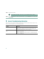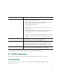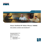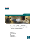
1
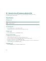
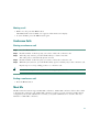
Quick Start Guide
Cisco IP Conference Station 7935
1
Getting Started
2
Installation
3
Features and Web Interface
4
Using the Cisco IP Conference Station 7935
5
General Troubleshooting Information
6
For More Information
7
For Technical Assistance
PRESENTED WITHOUT WARRANTY OF ANY KIND, EXPRESS OR IMPLIED. USERS MUST
TAKE FULL RESPONSIBILITY FOR THEIR APPLICATION OF ANY PRODUCTS.
THE SOFTWARE LICENSE AND LIMITED WARRANTY FOR THE ACCOMPANYING
PRODUCT ARE SET FORTH IN THE INFORMATION PACKET THAT SHIPPED WITH THE
PRODUCT AND ARE INCORPORATED HEREIN BY THIS REFERENCE. IF YOU ARE UNABLE
TO LOCATE THE SOFTWARE LICENSE OR LIMITED WARRANTY, CONTACT YOUR CISCO
REPRESENTATIVE FOR A COPY.
The following information is for FCC compliance of Class B devices: The equipment described in this
manual generates and may radiate radio-frequency energy. If it is not installed in accordance with
Cisco’s installation instructions, it may cause interference with radio and television reception. This
equipment has been tested and found to comply with the limits for a Class B digital device in
accordance with the specifications in part 15 of the FCC rules. These specifications are designed to
provide reasonable protection against such interference in a residential installation. However, there is
no guarantee that interference will not occur in a particular installation.
Modifying the equipment without Cisco’s written authorization may result in the equipment no longer
complying with FCC requirements for Class A or Class B digital devices. In that event, your right to
use the equipment may be limited by FCC regulations, and you may be required to correct any
interference to radio or television communications at your own expense.
You can determine whether your equipment is causing interference by turning it off. If the interference
stops, it was probably caused by the Cisco equipment or one of its peripheral devices. If the equipment
causes interference to radio or television reception, try to correct the interference by using one or more
of the following measures:
Turn the television or radio antenna until the interference stops.
Move the equipment to one side or the other of the television or radio.
Move the equipment farther away from the television or radio.
Plug the equipment into an outlet that is on a different circuit from the television or radio. (That is,
make certain the equipment and the television or radio are on circuits controlled by different circuit
breakers or fuses.)
Modifications to this product not authorized by Cisco Systems, Inc. could void the FCC approval and
negate your authority to operate the product.
The Cisco implementation of TCP header compression is an adaptation of a program developed by the
University of California, Berkeley (UCB) as part of UCB’s public domain version of the UNIX
operating system. All rights reserved. Copyright © 1981, Regents of the University of California.
NOTWITHSTANDING ANY OTHER WARRANTY HEREIN, ALL DOCUMENT FILES AND
SOFTWARE OF THESE SUPPLIERS ARE PROVIDED “AS IS” WITH ALL FAULTS. CISCO AND
THE ABOVE-NAMED SUPPLIERS DISCLAIM ALL WARRANTIES, EXPRESSED OR IMPLIED,
INCLUDING, WITHOUT LIMITATION, THOSE OF MERCHANTABILITY, FITNESS FOR A
PARTICULAR PURPOSE AND NONINFRINGEMENT OR ARISING FROM A COURSE OF
DEALING, USAGE, OR TRADE PRACTICE.
2
IN NO EVENT SHALL CISCO OR ITS SUPPLIERS BE LIABLE FOR ANY INDIRECT, SPECIAL,
CONSEQUENTIAL, OR INCIDENTAL DAMAGES, INCLUDING, WITHOUT LIMITATION,
LOST PROFITS OR LOSS OR DAMAGE TO DATA ARISING OUT OF THE USE OR INABILITY
TO USE THIS MANUAL, EVEN IF CISCO OR ITS SUPPLIERS HAVE BEEN ADVISED OF THE
POSSIBILITY OF SUCH DAMAGES.
3
4
1 Getting Started
This guide helps you quickly set up and use the Cisco IP Conference Station 7935. The IP Conference
Station requires Cisco CallManager and your system administrator must prepare the network for the
IP Conference Station. If a technician is not installing the IP Conference Station, verify with your
system administrator that the network is ready for the IP Conference Station. Be sure to read the
Release Notes and both the Parts List and the Safety Notices sections in this guide before you begin to
set up and use the IP Conference Station.
Note
If your IP Conference Station is already set up, skip to Section 3, Features and Web Interface.
Introduction
The Cisco IP Conference Station 7935 is an IP-based, hands-free conference room station that uses
Voice over IP (VoIP) technology. The IP Conference Station provides basic business conferencing
features and functions, such as Call Hold, Call Transfer, Call Release, Mute, and Conference, over an
IP network. It is designed to be used primarily on desktops and in small- to medium-sized conference
rooms to facilitate conference calling. It replaces a traditional analog conferencing unit in an
IP telephony network.
Package Contents
Review the following list to be sure that you have received all of the necessary items to install the
IP Conference Station.
• 1 Cisco IP Conference Station 7935
• 1 6 ft. CAT 5 Cable
• 1 25 ft. CAT 5 Cable
• 1 Power Interface Module (PIM)
• 1 Power Supply Unit (a country-specific power cord must be ordered separately)
• 1 Documentation Roadmap
• 1 Quick Start Guide
• 1 Quick Reference Card
• 1 Regulatory Compliance and Safety Information Guide
• 1 Warranty Card
5
Safety Notices
These are the safety considerations for using the IP Conference Station. Read these notices before you
install or use the IP Conference Station.
Warning
This warning symbol means danger. You are in a situation that could cause bodily injury.
Before you work on any equipment, be aware of the hazards involved with electrical
circuitry and be familiar with standard practices for preventing accidents.
Warning
Read the installation instructions before you connect the system to its power source.
Warning
Only trained and qualified personnel should be allowed to install, replace, or service this
equipment.
Warning
Ultimate disposal of this product should be handled according to all national laws and
regulations.
Warning
Do not work on the system or connect or disconnect cables during periods of lightning
activity.
Warning
To avoid electric shock, do not connect safety extra low voltage (SELV) circuits to
telephone network voltage (TNV) circuits. LAN ports contain SELV circuits, and WAN
ports contain TNV circuits. Some LAN and WAN ports both use RJ-45 connectors. Use
caution when connecting cables.
Warning
This product relies on the building's installation for short-circuit (overcurrent)
protection. Ensure that a fuse or circuit breaker no larger than 120 VAC, 15 A U.S. (240
VAC, 10 A international) is used on the phase conductors (all current-carrying
conductors).
6
Warning
The device is designed to work with TN power systems.
Warning
The plug-socket combination must be accessible at all times because it serves as the
main disconnecting device.
Caution
The Cisco IP Conference Station 7935 is inoperable during a power outage if it is not
supported by a UPS (uninterruptible power supply) when using a local power supply unit.
This affects your ability to reach 911.
Caution
Using a cell phone or mobile phone in close proximity to an IP Conference Station might
cause interference.
Note
To see translations of the safety warnings that appear in this publication, refer to the
Regulatory Compliance and Safety Information for the Cisco IP Conference Station 7935.
For more information on regulatory compliance and safety information, refer to the Regulatory
Compliance and Safety Information for the Cisco IP Conference Station 7935.
Where to Go for Help
If you require additional information or assistance with the IP Conference Station, contact your system
administrator. For technical assistance information, refer to the “For Technical Assistance” section on
page 33.
7
Related Documentation
In addition to this Quick Start Guide, you can reference the following publications:
• Cisco IP Conference Station 7935 Release Notes (available online, see URL below)
• Cisco IP Conference Station 7935 Administration Guide (available online, see URL below)
• Cisco IP Conference Station 7935 Quick Reference Card (included with your IP Conference
Station, and available online, see URL below)
• Regulatory Compliance and Safety Information for the Cisco IP Conference Station 7935
(included with your IP Conference Station, and available online, see URL below)
These publications are available on the Web at the following URL:
http://www.cisco.com/univercd/cc/td/doc/product/voice/c_ipphon/ip_7960/st7935/index.htm
For more documentation information, refer to the “For More Information” section on page 31.
2 Installation
This section provides basic installation instructions and information about obtaining best performance
with the Cisco IP Conference Station 7935.
Note
Make sure you have reviewed the Package Contents and read the Safety Notices in Section 1,
and read the Release Notes.
Before You Begin
Caution
To ensure a successful installation, verify with your system administrator that the
network is ready for the IP Conference Station, and that Cisco CallManager is installed
and configured for the IP Conference Station.
Installing and Connecting to the Network
Refer to the following diagram when you are installing the IP Conference Station.
Note
8
Daisy-chaining IP Conference Stations to other Cisco IP Phones is not supported and will not
work.
1
4
3
2
5
+
+
6
10
8
9
Foot
pad
48052
7
1
Power outlet in the wall
6
RJ-45 port on the bottom of the
IP Conference Station
2
Power supply unit
7
Free end of the 25 ft. CAT 5 cable
3
Power supply unit power cord 8
LAN connection on PIM
4
PIM
9
25 ft. CAT 5 cable connection on PIM
5
LAN connection
10 AC adapter port on PIM for power supply unit
9
Follow these steps to install and connect the IP Conference Station to the network.
Step 1
Place the IP Conference Station on a flat surface, for example, a conference room table or
desktop.
Step 2
Connect one end of the 6 ft. CAT 5 cable to your data network port and connect the other
end to the network (LAN) port on the PIM.
Step 3
Connect the free end of the 25 ft. CAT 5 cable to the RJ-45 port on the bottom of the
IP Conference Station. (The cable is pre-plugged into the PIM.)
Step 4
Connect the Power Supply unit to the AC adapter port on the PIM, and plug the other end
into a standard electrical power outlet in the wall.
Note
If you do not correctly connect the cables, PIM, power supply, and the
IP Conference Station unit, the IP Conference Station will not work.
Use of non-Cisco certified components may not work and may void the
IP Conference Station product warranty.
Startup Sequence
During the startup sequence, the LCD screen display shows the following messages.
Sequence Step
LCD Screen Message Display
Startup
Cisco Systems, Inc.
Polycom Technology
Copyright 2001
IP Address configuration
Renewing/Obtaining IP Address
Loading Application
Configuring IP
Press Menu to Reconfigure
Cisco CallManager configuration
Station IP (IP address)
Contacting (IP address)
10
Sequence Step
LCD Screen Message Display
Cisco CallManager registration
Opening: CM IP address
Registering
Initialization complete
Note
Press the Phone Key to get a dial tone
The startup process may take several minutes, and some of these messages may not appear
due to the access speed of your network.
For Best Performance
To ensure best performance with the IP Conference Station, follow these guidelines:
• Recommended room conditions include: closed offices and conference rooms up to 20 ft. x 30 ft.
in dimension without m ajor glass/ceramic surfaces and with normal background air-conditioning
noise
• Place the IP Conference Station in the center of a conference table or desk in a small- to
medium-sized conference room
• Do not shuffle papers near the IP Conference Station
• Seat all conference participants the same distance from the IP Conference Station
• Speak at normal conversation levels and direct your voice toward the IP Conference Station
• Do not move the IP Conference Station while on a call
3 Features and Web Interface
This section describes the features and Web interface for the Cisco IP Conference Station 7935.
Features
The IP Conference Station provides basic business conferencing features and functions, such as Call
Hold, Call Transfer, Call Release, Mute, and Conference over an IP network. It is designed to be used
primarily on desktops and in small- to medium-sized conference rooms to facilitate conference calling.
The IP Conference Station replaces a traditional analog conferencing unit on an IP telephony
network.
11
1
2
3
4
12
5
11
6
10
8
1
LEDs
49735
7
9
Provide call status indicators.
Call State Off: LEDs All off
Dial Tone On: LEDs All Green
Dialing: LEDs All Green
Connected: LEDs All Green
Mute: LEDs All Red and blinking
Hold: LEDs All Red and on
Incoming Call: LEDs All Green and blink with ring
Ringing: LEDs All Green and blink with ring
12
2
LCD screen
Provides a status indicator that reads “Press the Phone Key to get a dial
tone” when the IP Conference Station is online and fully operational. In
the resting display, the LCD screen shows the date and time, IP address,
and local phone number assigned to the IP Conference Station. Also
displays the IP Conference Station system status, including configuration
and all administrative settings.
3
Scroll buttons
Allow you to scroll through the menus or through an open list in the LCD
screen.
4
Select button
Selects a menu option or list item that is highlighted.
Select
5
Softkeys
Answer: picks up the current call
Conf: adds a party to a conference call
Corp Dir: lets you search a corporate directory for a number to call
End Call: ends a call and returns to the resting display or to the active
call list
Hold: puts the active call on hold
GPickup: lets you pick up a call within your group or another group
Pickup: lets you pick up a call within your group
Ph Book: opens the phone book
New Call: lets you dial a new number
Resume: returns to the selected held call
Transfer: transfers the current call
13
6
Volume buttons
Increase or decrease the volume of the call, speaker, ringer, or dial tone,
depending on which sound is currently active.
7
Mute button
Turns call muting on or off.
8
Dialing pad
Allows you to dial phone numbers, add or edit phone book entries, and
enter other input depending on the menu selected.
9
Redial button
Automatically redials the last dialed number.
Redial
10
Phone button
Allows you to get dial tone, answer an incoming call, and hang up a call.
11
Exit button
Returns to the resting LCD screen from a menu, a list, or the phone book.
Exit
12
Menu button
Menu
Opens and closes the main menu on the IP Conference Station. The main
menu includes the following selections:
Call Functions: opens the call function options, including Meet Me, Park,
Pick-up, Group Pick-up, and Transfer.
Phone Book: opens the phone book.
Settings: opens the Settings options, including Contrast, Language,
Ringer, Time Format, and Date Format.
Admin Setup: opens Admin Setup (requires administrator password).
14
Web Interface
Some of the features and functions of the IP Conference Station can be configured through the
Cisco IP Conference Station 7935 Web Interface.
Description of the Web Interface
The IP Conference Station Web Interface appears in your Web browser as a tri-pane window. The
browser menu and toolbar appear at the top of the window, the Table of Contents links appear in the
left navigation pane, and the linked information and configuration fields appear in the right pane. A
banner also appears in the top right corner of the right pane and remains persistent through all the
pages in the Web interface. The banner information includes: software version, protocol type, boot
load ID, application load ID, IP address, MAC address, and local number.
The content of the Web interface is different for administrators and end-users. Both the administator
and end-user views require login passwords. If you are an administrator, see the
Cisco IP Conference Station 7935 Administration Guide for information on administrator settings
available in the Web interface.
Using the Web Interface
To access the IP Conference Station Web Interface follow these instructions.
Step 1
Open your Web browser.
Step 2
In the address field type: http://IP address of the IP Conference Station:<HTTP Port
Number>
where HTTP Port Number is the number assigned by your system administrator. If this
number is not assigned, you do not need to enter it. Contact your system administrator if you
have difficulty opening the Web interface.
The Web interface appears, and the initial page is the Login page.
Note
Configuration information applies to the specific IP Conference Station associated
with the IP address you enter.
15
Step 3
In the password field, enter the end-user password and click Login.
Note
Step 4
The default end-user password is 7935. If you do not know the password, contact
your system administrator.
To log off, click User Logout.
End-user Settings
The End-user Settings include the following Web pages:
• Phone Book
• Sounds
• Time & Date
• Diagnostics
• Password Change
All the Web pages include online help information through the “i” icon. Each page is described in the
sections that follow.
Phone Book
The Phone Book Web page lets you quickly add, delete, and edit entries. You can also dial numbers
from the phone book.
On the Phone Book Web page, you can view entries by alphabetical sequence or by numbers only.
16
Opening the Phone Book Web page
• Click Phone Book in the navigation pane.
• To view the entries by alphabetic sequence, click one of the letter combinations, for example to
view entries beginning with the letter “D”, click DEF.
• To view the entries by phone number, click Numbers only.
Adding an entry
Step 1
Click the Add button.
Step 2
Enter the phone number, last and first name, and company name.
Note
Step 3
The phone number and last name are required entries.
Click Add New Entry.
Repeat these steps to add other entries to the phone book.
Deleting an entry
Step 1
Select an entry.
Step 2
Click the Delete button.
Step 3
Confirm the deletion by clicking the Delete button again.
Editing an entry
Step 1
Select an entry.
Step 2
Click the Edit button.
Make any changes to the entry.
Step 3
Click the Update button to save your changes.
17
Dialing a number from the Phone Book
• Select an entry and click Dial.
Sounds
The Sounds Web page lets you select the ringer sound and the dial tone.
Opening the Sounds Web page
• Click Sounds in the navigation pane.
Changing the ringer sound
Step 1
Select a ringer sound from the list box.
There are five ringer sounds: Pro, Biz, Euro, Chirp, Bell, and also Ringer Off.
Step 2
Click Set Ringer.
Step 3
Click Test Ringer to hear the sound you selected.
Note
If you select Ringer Off, the ringer sound on the IP Conference Station is turned off.
Time & Date
The Time & Date Web page lets you change the time and date formats that display in the LCD screen.
Opening the Time & Date Web page
• Click Time & Date in the navigation pane.
Changing the time format
• Select the 12-hour clock option button for 12-hour time format.
• Select the 24-hour clock option button for 24-hour time format.
• Click Change to save your changes.
18
Changing the date format
• Select the MM/DD/YY option button for a month/date/year format.
• Select the DD/MM/YY option button for a day/month/year format.
•
Click Change to save your changes.
Diagnostics
The Diagnostics Web page lets you test network connectivity to another device.
Opening the Diagnostics Web page
• Click Diagnostics in the navigation pane.
Pinging another device
Step 1
Enter the IP address of the device you want to ping.
Step 2
Click Ping.
You should receive a response back from the device.
Password Change
The Password Change page lets you change your user password.
Step 1
Click Password Change in the navigation pane.
Step 2
In the Old User Password box, enter the current user password.
Step 3
In the New User Password box, enter the new user password.
Step 4
In the Confirm User Password box, enter the new user password again.
Step 5
Click Change.
19
4 Using the Cisco IP Conference Station 7935
This section provides step-by step instructions for using the features and functions of the
Cisco IP Conference Station 7935.
Basic Features
Placing a call
Step 1
Press the Phone button.
Step 2
Dial the number.
Answering a call
• Press the Phone button or the Answer softkey.
The active call appears in the active call list in the LCD screen.
Ending a call
• Press the Phone button or the End Call softkey.
Placing a call on hold
• While on a call, press the Hold softkey.
The held call appears in the active call list in the LCD screen.
To place another call, press the New Call softkey and then dial the number.
• To return to the held call, press the Resume softkey.
• If multiple calls on are on hold, press the Up or Down scroll button to select a call in the active
call list and then press the Resume softkey.
Redialing a call
• Press the Redial button to dial the last number called.
20
Muting a call
• While on a call, press the Mute button.
The LEDs blink red and a Mute icon appears in the LCD screen display.
• To turn off Mute, press the Mute button again.
Conference Calls
Placing a conference call
Step 1
Press the Phone button.
Step 2
Dial the number of the first party you want to add to the conference call.
Step 3
After the party answers, press the Conf softkey to obtain a new line.
The other party is automatically placed on hold.
Step 4
Dial the number of the next party you want to add to the conference call.
Step 5
When the party answers, press the Conf softkey again to add the party to the conference call.
Repeat steps 3-5 to keep adding parties to a conference call.
Tip
You can also add parties to a conference call using the phone book.
Ending a conference call
• Press the Phone button
Meet Me
The IP Conference Station supports Meet Me conferences. A Meet Me conference allows other callers
to dial into the conference call. A Meet Me conference requires a special conference number that is
configured by the system administrator. Contact your system administrator to obtain a directory
number for a Meet Me conference.
21
Establishing a Meet Me conference
Step 1
Press the Phone button.
Step 2
Press the Menu button.
Step 3
Select Call Functions and then select Meet Me.
Step 4
Dial the Meet Me conference number.
Step 5
Follow the voice instructions to establish the Meet Me conference.
Joining a Meet Me conference
• Dial the Meet Me conference number provided by the Meet Me conference coordinator.
You are connected to the conference once the conference initiator has dialed in and established the
conference.
Call Transfer
To Transfer a call
Step 1
While on a call, press the Transfer softkey.
This places the call on hold.
Step 2
Dial the number to which you want to transfer the call.
Step 3
When you hear ringing, press the Transfer softkey again, or when the party answers, announce
the call and then press the Transfer softkey.
Note
If the call fails to transfer, press the Resume softkey to return to the original call.
Call Park
The IP Conference Station allows you to store or “park” a call at a specified number and then use any
other phone in the Cisco CallManager system (for example, a phone in someone else’s office or in a
conference room) to retrieve the call. Call Park numbers are configured by the system administrator.
22
Parking a call
Step 1
During an active call, press the Menu button.
Step 2
Select Call Functions and press the Select button.
Step 3
Select Park and then press the Select button.
The display shows the number to which the call is parked.
Step 4
Make a note of the Call Park number. The call is now parked at that number, allowing you to
retrieve it from another phone.
Note
Step 5
You have a limited amount of time to retrieve the parked call before it reverts to
ringing at its original destination. Contact your system administrator for the time
limit information.
To retrieve the parked call from any phone in the Cisco CallManager system, dial the Call
Park number at which the call was parked.
Call Pickup
The IP Conference Station allows you to answer a call that comes in on a telephone extension other
than on your IP Conference Station. When you hear an incoming call ringing on another phone, you
can redirect the call to your IP Conference Station by using the call pickup feature.
There are two types of call pickup available on the IP Conference Station:
• Call Pickup—pick up incoming calls within your own group. The appropriate call pickup group
number is dialed automatically when you choose this feature.
• Group Call Pickup—pick up incoming calls within your own group or in other groups. You must
dial the appropriate call pickup group number when using this feature.
These features are only available if your system administrator configured your IP Conference Station
to support them. The IP Conference Station does not support these features by default.
23
Picking Up Calls in Your Group
Call Pickup allows you to pick up incoming calls within your own group. When you activate Call
Pickup, it automatically dials the call pickup group number associated with the IP Conference Station.
If there is a call coming in on another telephone number in that same group, the call immediately
begins ringing on the IP Conference Station. If there is more than one incoming call in the pickup
group, then you receive the first unanswered call. If there is no unanswered call in the group when you
activate Call Pickup, then the IP Conference Station is available to receive the next call.
Step 1
Press the Phone button.
Step 2
Press the PickUp softkey.
Step 3
Answer the incoming call that is redirected to the IP Conference Station.
Picking Up Calls Outside Your Group
Group Call Pickup allows you to pick up incoming calls within your own group or in other groups.
You must dial the appropriate call pickup group number when using this feature.
If there is a call coming in on another telephone number in the call pickup group you dialed, that call
immediately begins ringing on the IP Conference Station. If there is more than one incoming call in the
pickup group, then you receive the first unanswered call. If there is no unanswered call in the group,
or if you dial an invalid call pickup group number, you receive a fast busy tone.
Step 1
Press the Phone button.
Step 2
Press the GPickUp softkey.
Step 3
Dial the desired group call pickup number.
Step 4
Answer the incoming call that is redirected to the IP Conference Station.
Step 5
To dial a different group call pickup number, hang up and begin again at Step 1.
Volume Controls
To adjust the speakerphone volume
• Press the Up or Down volume button to increase or decrease the volume.
24
To adjust the dial tone volume
Step 1
Press the Phone button. You will hear a dial tone.
Step 2
Press the Up or Down volume button to increase or decrease the volume.
To adjust the ringer volume
• Press the Up or Down volume button to increase or decrease the volume.
Corporate Directory
You can access a directory of employee names and phone numbers on the IP Conference Station. You
can search the corporate directory by name and by phone number.
Search by Name
Follow this procedure to search the corporate directory by name.
Step 1
Press the Corp Dir softkey.
The search screen displays. You can search by First Name or Last Name, or both.
Step 2
Using the keypad, enter the search criteria, namely First Name and Last Name. Press the Up
or Down scroll button to select a field.
When searching by name, you can enter one or more characters to broaden or narrow your
search.
When entering letters, select the appropriate number key for the letter you want, and press
that key the equivalent number of times for the correct letter. For example, to enter a B, press
the 2 key two times, and to enter a C, press the 2 key three times.
Use the < softkey to go backward while entering search data.
To cancel a search, press the Cancel softkey.
Step 3
Press the Search softkey to start the search.
The message “Searching...” flashes on the LCD screen display.
Step 4
After the search results display, use the Up or Down scroll button to select an entry.
If the search results include more than 32 entries, you can press the more >> softkey followed
by the Next softkey to display the next group of entries.
25
To go back to the previous group entries, press the more >> softkey followed by the Back
softkey.
To return to the Search screen, press the more >> softkey followed by the NewSearch softkey.
Step 5
Press the Dial softkey to call the number. To edit the number before calling, press the EditDial
softkey.
Step 6
To exit the directory, press the Exit softkey or the Exit button.
Search by Phone Number
Follow this procedure to search the corporate directory by phone number.
Step 1
Press the Corp Dir softkey.
The search screen displays.
Step 2
Press the Up or Down scroll button to select the Number field.
Using the keypad, enter the number. When searching by number, you can enter one or more
digits to broaden or narrow your search.
Use the < softkey to go backward while entering search data.
To cancel a search, press the Cancel softkey.
Step 3
Press the Search softkey to start the search.
The message “Searching...” flashes on the LCD screen display.
Step 4
After the search results display, use the Up or Down scroll button to select an entry.
If the search results include more than 32 entries, you can press the more >> softkey followed
by the Next softkey to display the next group of entries.
To go back to the previous group entries, press the more >> softkey followed by the Back
softkey.
To return to the Search screen, press the more >> softkey followed by the NewSearch softkey.
Step 5
Press the Dial softkey to call the number. To edit the number before calling, press the EditDial
softkey.
Step 6
To exit the directory, press the Exit softkey or the Exit button.
26
Phone Book
The phone book is a convenient way to store frequently dialed conference call numbers.
Timesaver
You can also use the Cisco IP Conference Station 7935 Web Interface to access the phone
book.
Opening the Phone Book
• Press the Ph Book softkey.
Calling a number in the Phone Book
Step 1
Press the Up or Down scroll button to select the entry you want.
Step 2
Press the Call softkey.
Adding an entry in the Phone Book
• Press the New Entry softkey.
– Using the Dialing pad, enter the last name, first name, and phone number for the new entry.
Press the Up or Down scroll buton to select the Last, First, or Number fields.
When entering letters, select the appropriate number key for the letter you want, and press
that key the equivalent number of times for the correct letter. For example, to enter a B, press
the 2 key two times, and to enter a C, press the 2 key three times.
Use the < softkey to go backward while entering data.
– Press the Save softkey to save the new entry, or to exit without saving, press the Exit softkey.
Note
You can add a maximum of 20 entries to the phone book.
27
Editing an entry in the Phone Book
Step 1
Press the Up or Down scroll button to select an entry. Press the View/Edit softkey.
You can change or clear the selected entry using the Change or Clr Entry softkeys. Press the
< softkey to go backward when changing an entry.
To exit without saving, press the Exit softkey.
Step 2
Press the Save softkey to save your changes.
Step 3
Press the Menu button to return to the main menu, or press the Exit button to return to the
resting display.
Settings
You can adjust some of the settings on the IP Conference Station.
Timesaver
You can also use the Cisco IP Conference Station 7935 Web Interface to change settings.
Time and Date
Step 1
Press the Menu button.
Step 2
Press the Up or Down scroll button to select Settings. Press the Select button.
Step 3
Press the Up or Down scroll button to select Time Format.
Step 4
Press the 12 Hr or 24 Hr softkey to select 12 hr. or 24 hr. format respectively.
Step 5
Press the Up or Down scroll button to select Date Format.
Step 6
Press the MM/DD/YY or DD/MM/YY softkey to select a mm/dd or dd/mm format.
Step 7
Press the Menu button to return to the main menu, or press the Exit button to return to the
resting display.
28
LCD Screen Contrast
Step 1
Press the Menu button.
Step 2
Press the Up or Down scroll button to select Settings. Press the Select button.
Step 3
Press the Up or Down scroll button to select Contrast.
Step 4
Press the - or + softkey to set the desired contrast of the LCD screen.
Step 5
Press the Menu button to return to the main menu, or press the Exit button to return to the
resting display.
Language
Step 1
Press the Menu button.
Step 2
Press the Up or Down scroll button to select Settings. Press the Select button.
Step 3
Press the Up or Down scroll button to select the Language entry.
The default language is English.
Step 4
Press the Change softkey to view the languages list. Press the Up or Down scroll button to
highlight the desired language (English, French, German, or Spanish).
Step 5
Press the Menu button to return to the main menu, or press the Exit button to return to the
resting display.
Ringer
Step 1
Press the Menu button.
Step 2
Press the Up or Down scroll button to select Settings. Press the Select button.
Step 3
Press the Up or Down scroll button to select Ringer.
Step 4
Press the Change softkey to display the ringer list.
You can select from five different ring sounds.
Step 5
Press the Up or Down scroll button to select a ringer sound (Pro, Biz, Euro, Chirp, Bell, and
also Ringer Off).
Step 6
Press the Listen softkey to hear the ring sound.
Repeat these Steps 5 and 6 until you have selected the ringer sound you want.
29
Step 7
Press the Save softkey.
Note
Step 8
Selecting Ringer Off shuts off the ringer sound on the IP Conference Station.
Press the Menu button to return to the main menu, or press the Exit button to return to the
resting display.
5 General Troubleshooting Information
This section provides general troubleshooting information for the Cisco IP Conference Station 7935.
Refer to the following table if you are having difficulties.
Problem
Resolution
No dial tone
Check that all connections are tight and in place.
Make sure all connections are correct. See the “Installing and
Connecting to the Network” section on page 8.
IP Conference Station does not
ring
Check that the ringer setting is not “Ringer Off.”
Check the volume level.
Make sure that the IP Conference Station is communicating with
the Cisco CallManager.
30
Problem
IP Conference Station resetting
Resolution
• The IP Conference Station resets when it loses contact with
the Cisco CallManager software.
The following status message appears in the LCD screen if the
IP Conference Station loses contact with the
Cisco CallManager software:
Registering
• The IP Conference Station resets when it loses contact with
the network.
The following status message appears in the LCD screen if the
IP Conference Station loses contact with the network:
Configuring IP
These lost connections can be due to any network connectivity
disruption, including cable breaks, switch outages, and switch
reboots.
No display on the LCD screen
Check to make sure that there is power.
Make sure that the power supply is plugged in.
LCD screen display issues
You might see Beat frequencies (scan lines) in the LCD screen if
you are using certain types of older fluorescent lights in your
building. Moving the IP Conference Station away from the lights,
or replacing the lights, should resolve the problem.
DTMF delay
When you are on a call that requires keypad input, if you press the
keys too quickly, some of them might not be recognized.
If you are experiencing other difficulties, contact your system administrator.
6 For More Information
The following sections provide sources for obtaining documentation from Cisco Systems.
World Wide Web
You can access the most current Cisco documentation on the World Wide Web at this URL:
http://www.cisco.com
31
Documentation CD-ROM
Cisco documentation and additional literature are available in a CD-ROM package. The
Documentation CD-ROM is updated monthly and may be more current than printed documentation.
The CD-ROM package is available as a single unit or as an annual subscription.
Ordering Documentation
You can order Cisco documentation in these ways:
• Registered Cisco.com users (Cisco direct customers) can order Cisco product documentation from
the Networking Products MarketPlace:
http://www.cisco.com/cgi-bin/order/order_root.pl
• Registered Cisco.com users can order the Documentation CD-ROM through the online
Subscription Store:
http://www.cisco.com/go/subscription
• Nonregistered Cisco.com users can order documentation through a local account representative
by calling Cisco Systems Corporate Headquarters (California, U.S.A.) at 408 526-7208 or,
elsewhere in North America, by calling 800 553-NETS (6387).
Documentation Feedback
You can submit comments electronically on Cisco.com. In the Cisco Documentation home page, click
the Fax or Email option in the “Leave Feedback” section at the bottom of the page.
You can e-mail your comments to [email protected].
You can submit your comments by mail by using the response card behind the front cover of your
document or by writing to the following address:
Cisco Systems
Attn: Document Resource Connection
170 West Tasman Drive
San Jose, CA 95134-9883
We appreciate your comments.
32
7 For Technical Assistance
Cisco provides Cisco.com as a starting point for all technical assistance. Customers and partners can
obtain online documentation, troubleshooting tips, and sample configurations from online tools by
using the Cisco Technical Assistance Center (TAC) Web Site. Cisco.com registered users have complete
access to the technical support resources on the Cisco TAC Web Site.
Cisco.com
Cisco.com is the foundation of a suite of interactive, networked services that provides immediate, open
access to Cisco information, networking solutions, services, programs, and resources at any time, from
anywhere in the world.
Cisco.com is a highly integrated Internet application and a powerful, easy-to-use tool that provides a
broad range of features and services to help you with these tasks:
• Streamline business processes and improve productivity
• Resolve technical issues with online support
• Download and test software packages
• Order Cisco learning materials and merchandise
• Register for online skill assessment, training, and certification programs
If you want to obtain customized information and service, you can self-register on Cisco.com. To
access Cisco.com, go to this URL:
http://www.cisco.com
Technical Assistance Center
The Cisco Technical Assistance Center (TAC) is available to all customers who need technical
assistance with a Cisco product, technology, or solution. Two levels of support are available: the Cisco
TAC Web Site and the Cisco TAC Escalation Center.
Cisco TAC inquiries are categorized according to the urgency of the issue:
• Priority level 4 (P4)—You need information or assistance concerning Cisco product capabilities,
product installation, or basic product configuration.
• Priority level 3 (P3)—Your network performance is degraded. Network functionality is noticeably
impaired, but most business operations continue.
33
• Priority level 2 (P2)—Your production network is severely degraded, affecting significant aspects
of business operations. No workaround is available.
• Priority level 1 (P1)—Your production network is down, and a critical impact to business
operations will occur if service is not restored quickly. No workaround is available.
The Cisco TAC resource that you choose is based on the priority of the problem and the conditions of
service contracts, when applicable.
Cisco TAC Website
You can use the Cisco TAC Web Site to resolve P3 and P4 issues yourself, saving both cost and time.
The site provides around-the-clock access to online tools, knowledge bases, and software. To access
the Cisco TAC Web Site, go to this URL:
http://www.cisco.com/tac
All customers, partners, and resellers who have a valid Cisco service contract have complete access to
the technical support resources on the Cisco TAC Web Site. The Cisco TAC Web Site requires a
Cisco.com login ID and password. If you have a valid service contract but do not have a login ID or
password, go to this URL to register:
http://www.cisco.com/register/
If you are a Cisco.com registered user, and you cannot resolve your technical issues by using the Cisco
TAC Web Site, you can open a case online by using the TAC Case Open tool at this URL:
http://www.cisco.com/tac/caseopen
If you have Internet access, we recommend that you open P3 and P4 cases through the Cisco TAC
Web Site.
Cisco TAC Escalation Center
The Cisco TAC Escalation Center addresses priority level 1 or priority level 2 issues. These
classifications are assigned when severe network degradation significantly impacts business
operations. When you contact the TAC Escalation Center with a P1 or P2 problem, a Cisco TAC
engineer automatically opens a case.
To obtain a directory of toll-free Cisco TAC telephone numbers for your country, go to this URL:
http://www.cisco.com/warp/public/687/Directory/DirTAC.shtml
Before calling, please check with your network operations center to determine the level of Cisco
support services to which your company is entitled: for example, SMARTnet, SMARTnet Onsite, or
Network Supported Accounts (NSA). When you call the center, please have available your service
agreement number and your product serial number.
34
35
Corporate Headquarters
Cisco Systems, Inc.
170 West Tasman Drive
San Jose, CA 95134-1706
USA
www.cisco.com
Tel: 408 526-4000
800 553-NETS (6387)
Fax: 408 526-4100
European Headquarters
Cisco Systems International BV
Haarlerbergpark
Haarlerbergweg 13-19
1101 CH Amsterdam
The Netherlands
www-europe.cisco.com
Tel: 31 0 20 357 1000
Fax: 31 0 20 357 1100
Americas Headquarters
Cisco Systems, Inc.
170 West Tasman Drive
San Jose, CA 95134-1706
USA
www.cisco.com
Tel: 408 526-7660
Fax: 408 527-0883
Asia Pacific Headquarters
Cisco Systems, Inc.
Capital Tower
168 Robinson Road
#22-01 to #29-01
Singapore 068912
www.cisco.com
Tel: +65 6317 7777
Fax: +65 6317 7799
Cisco Systems has more than 200 offices in the following countries. Addresses, phone numbers, and fax numbers are listed on the
Cisco Web site at www.cisco.com/go/offices
Argentina • Australia • Austria • Belgium • Brazil • Bulgaria • Canada • Chile • China PRC • Colombia • Costa Rica • Croatia • Czech Republic • Denmark • Dubai, UAE
Finland • France • Germany • Greece • Hong Kong SAR • Hungary • India • Indonesia • Ireland • Israel • Italy • Japan • Korea • Luxembourg • Malaysia • Mexico
The Netherlands • New Zealand • Norway • Peru • Philippines • Poland • Portugal • Puerto Rico • Romania • Russia • Saudi Arabia • Scotland • Singapore • Slovakia
Slovenia • South Africa • Spain • Sweden • Switzerland • Taiwan • Thailand • Turkey • Ukraine • United Kingdom • United States • Venezuela • Vietnam • Zimbabwe
Copyright © 2003 Cisco Systems, Inc. All rights reserved. CCIP, CCSP, the Cisco Arrow logo, the Cisco Powered Network mark, the Cisco Systems Verified logo, Cisco Unity, Follow
Me Browsing, FormShare, iQ Breakthrough, iQ FastTrack, the iQ logo, iQ Net Readiness Scorecard, Networking Academy, ScriptShare, SMARTnet, TransPath, and Voice LAN are
trademarks of Cisco Systems, Inc.; Changing the Way We Work, Live, Play, and Learn, The Fastest Way to Increase Your Internet Quotient, and iQuick Study are service marks of
Cisco Systems, Inc.; and Aironet, ASIST, BPX, Catalyst, CCDA, CCDP, CCIE, CCNA, CCNP, Cisco, the Cisco Certified Internetwork Expert logo, Cisco IOS, the Cisco IOS logo,
Cisco Press, Cisco Systems, Cisco Systems Capital, the Cisco Systems logo, Empowering the Internet Generation, Enterprise/Solver, EtherChannel, EtherSwitch, Fast Step, GigaStack,
Internet Quotient, IOS, IP/TV, iQ Expertise, LightStream, MGX, MICA, the Networkers logo, Network Registrar, Packet, PIX, Post-Routing, Pre-Routing, RateMUX, Registrar,
SlideCast, StrataView Plus, Stratm, SwitchProbe, TeleRouter, and VCO are registered trademarks of Cisco Systems, Inc. and/or its affiliates in the U.S. and certain other countries.
All other trademarks mentioned in this document or Web site are the property of their respective owners. The use of the word partner does not imply a partnership relationship
between Cisco and any other company. (0301R)
Printed in Thailand.
78-12231-03
DOC-7812231=
1725-06622-001 Rev C