1
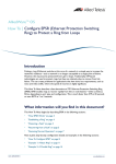
Configuring the Cisco 7920 Wireless IP Phone with
WEP Keys, VLANs, and LEAP
Document ID: 43622
Introduction
Prerequisites
Requirements
Components Used
Related Products
Conventions
Background Theory
Network Diagram
Using Open Authentication and Static WEP Keys
Configuring the Cisco 7920
Configuring the Cisco Aironet 1200 AP
Using Open Authentication, Static WEP Keys, and VLANs
Configuring the Cisco 7920
Configuring the Cisco Aironet 1200 AP with a VLAN
Configuring 802.1Q Trunking on the Catalyst 2924 XL
Configuring the Inter−VLAN Router
Using Cisco LEAP
Configuring the Cisco 7920
Configuring the Cisco Aironet 1200 AP for LEAP
Configuring the Cisco Secure Server for LEAP
Troubleshooting Guidelines
Cisco 7920 Exhibits Problems After Configuration Changes
Cisco 7920 Error Message − Association Failed, No AP Found
Cisco 7920 Error Message − No Service IP Config Failed
Cisco 7920 Error Message − Registration Rejected
Cisco 7920 Error Message − Connecting to CallManager 0−5
Cisco 7920 Configuration Utility Can Not Connect to 7920 − Connection Busy
LEAP Authentication Fails
General Troubleshooting Hints
Appendix: Configuring the Cisco 7920 with CallManager
Related Information
Introduction
This document explains how to configure the Cisco 7920 Wireless IP Phone (Cisco 7920) in common
network scenarios. It starts with the most basic configuration required to implement a Cisco 7920. It goes on
to explain the next level of complexity, which is the use of VLANs. The final level of complexity is the use of
Cisco Secure Access Control Server (ACS) for security. The goal of this document is to provide the reader
with a single document that covers the basic tasks required to implement a Cisco 7920 in a lab environment,
so that the user can use these skills to implement a Cisco 7920 in a live environment. The reason that this
document is targeted at a lab environment is that it is impossible to cover, in a single document, all of the
possible permutations of equipment and features that are available to implement a Cisco 7920 in a live
environment.
The Cisco 7920 is the first Cisco product to combine Voice over IP (VoIP) technology, Wireless LAN
(WLAN) technology, Quality of Service (QoS), and Access/Authentication/Authorization (AAA) security. In
order to successfully implement and support the Cisco 7920, system administrators must become familiar with
all of these technology areas.
This document was created primarily for readers who have limited experience with one or more of the
products and technologies required to install and configure a Cisco 7920 IP Phone. It will also benefit readers
that have a great deal of experience in some of the areas but not others.
QoS is not covered in this document, because it is not required that you implement QoS to bring a Cisco 7920
online to place calls. The QoS (Quality of Service) Technical Support page contains links to several very good
documents about the implementation of QoS in VoIP environments.
This document also provides some troubleshooting guidelines. It is not intended to be a complete manual to
install, configure, or troubleshoot the Cisco 7920 or any of the other components that are used in this
document. The related documents that contain more detailed instructions are referenced in the subsequent
sections, as appropriate.
WLAN infrastructure devicessuch as the Cisco Aironet 350 Series Access Point (AP) or the Cisco Aironet
1200 Series APtreat the Cisco 7920 the same as any other wireless 802.11b client. Cisco CallManager treats
the Cisco 7920 like any other Cisco 7960 IP Phone. You can use the knowledge and skills that you already
have in these areas when you install, configure, and troubleshoot a Cisco 7920.
Prerequisites
Requirements
This document assumes that you have an operational Cisco CallManager 3.2 or later, a Catalyst switch that
supports 802.1Q VLANs, and a Cisco Secure ACS (if you are going to do Light Extensible Authentication
Protocol [LEAP]). It is also assumed that you have some experience with these products.
Though it is not required, it is helpful to confirmwith a PC or another wireless data clientthat your wireless
configuration can connect over the Cisco Aironet AP to an IP device on the other side of the AP.
Components Used
The information in this document is based on these software and hardware versions:
• Cisco 7920 Wireless IP Phone
• Cisco 7960 IP Phone
• Cisco CallManager 3.3(3)
• Catalyst 2924 XL version 12.0(5)WC5a
• Cisco 2651 Router version 12.2(15)T
• Cisco 1200 Series AP version 12.2(13)JA4
• Cisco Secure ACS Release 3.2
The information in this document was created from the devices in a specific lab environment. All of the
devices used in this document started with a cleared (default) configuration. If your network is live, make sure
that you understand the potential impact of any command.
Related Products
You can substitute any Catalyst Switch that supports 802.1Q trunking. If it is based on Cisco IOS® Software
(similar to a 2900 XL), then the configuration examples in this document should work. If it is based on
Catalyst OS, then you have to convert the examples as required.
You can substitute any Aironet Wireless device that supports 802.11b clients. The Cisco Aironet 1200 AP
examples provide some guidelines for how you should configure your Aironet device.
Conventions
For more information on document conventions, refer to the Cisco Technical Tips Conventions.
Background Theory
The Cisco 7920 is supported by Cisco CallManager 3.2 and later. It is configured as a Cisco 7960 IP Phone in
Cisco CallManager; however, it has its own image file. Wireless devices, such as the Cisco Aironet 1200 AP,
treat the Cisco 7920 like a typical wireless client.
If you are not already familiar with Wireless Security issues and best practices, refer to Wireless LAN
Security White Paper before you proceed with a live installation of a Cisco 7920.
You should be familiar with the basic administrative and user tasks for the Cisco 7920. The Cisco 7920
documentation is available in the Products and Services area of Cisco.com.
If you have not already configured the Cisco 7920 or any other Cisco IP Phone on your Cisco CallManager
server, see the Appendix: Configuring the Cisco 7920 with CallManager section of this document before you
begin. Add the additional IP phone at this time as well: it is required to perform VoIP test calls to and from
the Cisco 7920.
Tip: When you use the USB cable that is provided with the Cisco 7920 to configure it with the Cisco 7920
PC−based Configuration Utility, the Cisco 7920 appears as a network device on the PC. Any time that the
Cisco 7920 is connected to the PC through the USB cable, you can see that this connection exists. On the PC,
choose Start > Settings > Networking and Dial Up Connections. One of the connections is the Cisco 7920.
Do not make any changes to it. It is only used by the Cisco 7920 Configuration Utility through the USB port.
When you disconnect the Cisco 7920 from the PC, this interface disappears from your Networking and Dial
Up Connections until the next time that you connect it. Issue the ipconfig /all command (from a command
prompt on your PC) to view the IP settings used by the Cisco 7920 USB connection.
If you are not already familiar with the text editing mode for the Cisco 7920, consider these points:
• The asterisk (*) toggles between lower and upper case characters.
• The hash (#) allows you to enter Special Characters. Press the Back key to exit Special Character
mode.
• Press the Clear key to delete the previous character.
• The large buttons with white arrows move the cursor left and right.
• To enter a character, press the number button with the character that you want to use. Keep pressing
the button until the character shows up.
For example, to enter the letter z press the 9 key four times. To enter the letter Z, press the
asterisk first then press the 9 key four times.
Once the character that you want is displayed, wait for a few seconds. The cursor will move to the
right of the last character that you entered. To enter a number keep pressing the button until the
number appears.
Network Diagram
This document uses this network setup:
Using Open Authentication and Static WEP Keys
If you want to learn more about Wireless Security before you start this section, refer to these documents:
• Cisco Aironet Wireless LAN Security Overview
• Security Setup for the Cisco Aironet 350
• Wireless Virtual LAN Deployment Guide
This example is based on the use of open authentication and 128−bit static Wired Equivalent Privacy (WEP)
encryption keys.
Caution: It is not recommended to use Shared Key authentication because it is very easy to
compromise.
This task guides you through a very basic Cisco 7920 and Cisco Aironet 1200 AP configuration. This
configuration allows the Cisco 7920 to authenticate and associate with the 1200 AP. When you are done, the
Cisco 7920 should be able to register with the Cisco CallManager server.
Note: When you are using open authentication, the Cisco Aironet 1200 AP will authenticate all devices that
send it authentication requests. However, only devices with the correct WEP encryption keys will be able to
associate with the 1200 AP and to send traffic over it successfully.
Configuring the Cisco 7920
This subtask assumes that you have already installed the Cisco 7920 Configuration Utility that came with
your Cisco 7920. If you have not yet installed this utility, stop and do so now. The instructions for the
installation are included with your Cisco 7920.
Step−by−Step Instructions
The instructions in this section guide you through the minimum configuration steps that are required to enable
a Cisco 7920 with a static WEP key.
1. Turn on the Cisco 7920.
2. Choose Menu > Phone Settings > USB Enable / Disable [Enable] to enable the Cisco 7920 USB
port.
3. Connect the Cisco 7920 to the USB cable. (The USB cable should already be connected to the PC.)
4. Start the Cisco 7920 Configuration Utility on the PC.
Note: If you use Cisco Wireless IP Phone 7920 Firmware Release 2.0, use Cisco 7920 Configuration
Utility 2.0. If you use an earlier firmware version on the phones, then you must use an earlier version
of the Configuration Utility. Cisco 7920 Configuration Utility 2.0 can be download from Cisco 7920
Wireless Phone Software Downloads ( registered customers only) .
5. Log in to the Cisco 7920.
The default User Name is Admin. The default Password is cisco. Click OK.
6. When this popup window appears, click OK:
7. Choose Edit > Settings Wizard.
8. When this popup window appears, click Cancel:
9. Click Import to obtain the current settings on the Cisco 7920.
10. When this popup window appears, click OK.
11. Click the System Parameters tab.
The System Parameters configuration screen appears. In this case, the Cisco 7920 is using Dynamic
Host Configuration Protocol (DHCP) to obtain its IP parameters, including the TFTP address (Cisco
CallManager server).
12. Make any changes that your phone requires.
13. Click the RF Network tab.
The RF Network configuration screen appears.
14. Enter the Primary Service Set Identifier (SSID) for the Cisco Aironet 1200 AP. (You will be
configuring this value in the 1200 AP in the next subtask.) Leave the Transmit Power and the Data
Rate set to their default values.
15. Click the Network Security tab.
The Network Security configuration screen appears. This is the screen where you enter the
Authentication Type and the static WEP keys. The 128−bit WEP keys are created using 26
hexadecimal digits (1−9, A−F).
Note: The static WEP keys must be the same on the Cisco 7920 and on the wireless infrastructure
devices in your network (in this case, the Cisco Aironet 1200 AP). You might want to keep a copy of
them in a document in a secure location; once they are entered into a device, you can not determine
what the key is from the device itself. If you do not have a record of them, you will have to create new
keys when you add a new device or reconfigure an existing device.
Note: The Cisco 7920 supports up to four static WEP keys. Only one static WEP key is required.
Caution: Client devices that do not use Extensible Authentication Protocol (EAP) must contain
the Access Points transmit key in the same key slot in the client devices WEP key lists. However,
the key does not need to be selected as the transmit key in the clients WEP key list. If the transmit
keys are in different slots, then your Cisco 7920 will not be able to communicate with the Cisco
Aironet 1200 AP.
16. Enter at least one WEP key (in this case, 1234567890abcdef0987654321).
Note: This sample configuration only uses one WEP key. Your live network may require more.
17. Click the Phone Settings tab.
18. The Phone Settings configuration screen appears. Configure the Cisco Discovery Protocol (CDP)
parameters as shown in the next image. Enter the messages as appropriate.
Note: The Phone Lock Password tab is not covered in this document. Refer to the Cisco 7920
Administrator Guide for more information on this tab.
19. Click Export and the next popup window appears. It is not required that you save the settings to a
local file; but, if you would like to do so, click OK and then continue with the rest of this procedure.
Note: The static WEP keys are not saved in the configuration file. If you reset a phone to the factory
defaults, you can not just download the configuration to completely reconfigure it. You will still have
to re−enter the static WEP keys.
20. When this popup window appears, click OK:
21. Choose Connection > Logout.
22. When this popup window appears, click Yes:
23. When this popup window appears, click OK:
24. Choose File > Exit. The next popup window appears. If you want to save the Log History, click Yes
and save it to disk. Otherwise, click No.
25. Right−click the USB icon on the taskbar.
26. Select Cisco 7920 USB and click Stop.
27. When this popup window appears, click OK:
28. When this popup window appears, click OK:
29. Choose Menu > Phone Settings > USB Enable / Disable [Disable] to disable the Cisco 7920 USB
port.
Verifying
There are no steps to verify this part of the configuration. It can be verified at the end of the next subtasks.
Troubleshooting
All of the troubleshooting guidelines can be found in the Troubleshooting Guidelines section at the end of this
document.
Configuring the Cisco Aironet 1200 AP
The instructions in this section describe the minimum configuration steps to enable a Cisco Aironet 1200 AP
with static WEP keys. This will allow the Cisco 7920 to access the LAN and to register with a Cisco
CallManager server.
Step−by−Step Instructions
Tip: Right−click the Back button on your browser to quickly return to a previous page in the Cisco Aironet
1200 AP management pages.
1. Load the Cisco Aironet 1200 AP administration page into your browser with the address
http://1200ap−ip−address .
2. Use the left navigation bar to configure the Access Point.
a. Choose Security > SSID Manager.
b. On the SSID Properties page, select <NEW> in the Current SSID List and enter the SSID in
the SSID field.
For the purpose of the configuration, the SSID is kormakur. It should be the same one that
you previously entered in the Cisco 7920.
3. To edit the SSID, select the required one from the Current SSID List and edit it.
Because the configuration requires the use of Open Authentication, check Open Authentication in
the Authentication Settings area (it is checked by default, if you have not changed it).
4. Click Apply−All to apply the SSID and the Authentication settings for all of the Radio interfaces; or
click Apply−Radio0 to apply the settings only to Radio0.
5. When this popup warning appears, click OK:
6. Choose Security > Encryption Manager to configure the WEP keys.
a. In the Encryption Modes area, click the WEP Encryption radio button, and select
Mandatory.
b. Click the Encryption Key 1 radio button to set it as the Transmit Key, and enter the same
WEP key that you entered in the Cisco 7920 (in this case, 1234567890abcdef0987654321).
Note: The WEP key input appears as asterisks. This is normal behavior.
For more information on the configuration of WEP keys, refer to Configuring WEP and WEP
Features.
c. Leave the Key Size set to the default value (128 bit).
d. Click Apply−Radio0 or Apply−All (as appropriate) to save the settings.
7. When this popup warning appears, click OK:
Verifying
This section helps you to verify the association of the Cisco 7920 with the Cisco Aironet 1200 AP and with
the CallManager.
1. If you entered all of the settings correctly, the Cisco 7920 should have associated and authenticated
with the Cisco Aironet 1200 AP.
This appears on the Association page.
Note: You may have to refresh the page.
2. If the Cisco CallManager configuration is correct, the Cisco 7920 should have registered with the
CallManager server. You should now be able to place calls between the Cisco 7920 and your other IP
Phone.
Troubleshooting
All of the troubleshooting guidelines can be found in the Troubleshooting Guidelines section at the end of this
document.
Using Open Authentication, Static WEP Keys, and VLANs
This task adds support for VLANs, to build on the previous task. The implementation of VLANs requires
configuration changes on the Cisco 7920 and on the Cisco Aironet 1200 AP. The 1200 AP can be configured
with different SSIDs for each VLAN. For example, you can use VLAN1 as the SSID for VLAN1 and
VLAN2 as the SSID for VLAN2. The Cisco 7920 uses its SSID to determine which VLAN that it should
use. If you want the Cisco 7920 to use VLAN2 then you would configure its SSID to VLAN2.
In this example, VLAN1 is the default VLAN. The Cisco 7920 will be configured to use VLAN2, and then
VLAN2 will be added to the Cisco Aironet 1200 AP.
Configuring the Cisco 7920
Note: This task uses the same WEP key that was used in the first task. Therefore, it does not include the
instructions to establish the WEP key on the Cisco 7920.
This task assumes that you are using DHCP to obtain the correct IP address and default gateway for the Cisco
7920. You must also configure your DHCP server with a scope for the new VLAN. Refer to Using One
DHCP Server for Voice and Data Networks for more information on DHCP. If you use a static IP address and
default gateway address, then you must change the current IP address on the System Parameters tab in the
Cisco 7920 Configuration Utility to a legitimate address on the new subnet, before you export the new
configuration to the Cisco 7920. Change the IP address between Steps 11 and 12 in the next procedure.
Step−by−Step Instructions
The instructions in this section guide you through the minimum steps that are required to configure the Cisco
IP Phone 7920 to use VLAN2s SSID.
1. Turn on the Cisco 7920.
2. Choose Menu > Phone Settings > USB Enable / Disable [Enable] to enable the Cisco 7920 USB
port.
3. Connect the Cisco 7920 to the USB cable. (The USB cable should already be connected to the PC.)
4. Start the Cisco 7920 Configuration Utility.
5. Log in to the Cisco 7920.
The default User Name is Admin. The default Password is cisco. Click OK.
6. When this popup window appears, click OK:
7. Choose Edit > Settings Wizard.
8. When this popup window appears, click Cancel:
9. Click Import to obtain the current settings on the Cisco 7920.
10. When this popup window appears, click OK:
11. Click the RF Network tab.
The RF Network configuration screen appears. Change the SSID 1 value to VLAN2.
12. Click Export and the next popup window appears. It is not required that you save the settings to a
local file; but, if you would like to do so, click OK and then continue with the rest of this procedure.
Note: The static WEP keys are not saved in the configuration file. If you reset a phone to the factory
defaults, you can not just download the configuration to completely reconfigure it. You will still have
to re−enter the static WEP keys.
13. When this popup appears, click OK:
14. Choose Connection > Logout.
15. When this popup window appears, click Yes:
16. When this popup window appears, click OK:
17. Choose File > Exit. The next popup window appears. If you want to save the Log History, click Yes
and save it to disk. Otherwise, click No.
18. Right−click the USB icon on the taskbar.
19. Select Cisco 7920 USB and click Stop.
20. When this popup window appears, click OK:
21. When this popup window appears, click OK:
22. Choose Menu > Phone Settings > USB Enable / Disable [Disable] to disable the Cisco 7920 USB
port.
Note: If you have not yet configured VLAN on the Cisco Aironet 1200 AP, the Cisco 7920 will show
the error message No AP Found. This is the expected behavior.
Verifying
There are no steps to verify this part of the configuration. It can be verified at the end of the next subtask.
Troubleshooting
All of the troubleshooting guidelines can be found in the Troubleshooting Guidelines section at the end of this
document.
Configuring the Cisco Aironet 1200 AP with a VLAN
The instructions in this section guide you through the minimum configuration steps to enable VLANs on an
Cisco Aironet 1200 AP. There are two subtasks that must be preformed. The first is to create the VLANs. The
second is to create the additional SSIDs and assign them to the VLANs. In this task, you will create VLAN1
and VLAN2.
Step−by−Step Instructions for Configuring VLAN 1 (default)
The steps in this section describe the process to configure VLAN1 (the default VLAN) on the Cisco Aironet
1200 AP.
1. Load the Cisco Aironet 1200 AP administration page into your browser with the address
http://1200ap−ip−address .
2. Before you configure the VLANs, create SSIDs for the VLANs.
In this case, assume that the SSID for VLAN1 and for VLAN2 are created as VLAN1 and
VLAN2. See the previous procedure to create the SSIDs.
a. Choose Services > VLAN.
b. To create the default VLAN, select <NEW> and set the VLAN ID field to 1.
c. Check the Native VLAN and the appropriate Radio check boxes, and select VLAN1 on the
SSID drop−down list.
d. Click Apply to save the settings.
3. When this popup warning appears, click OK:
4. When this popup warning appears, click OK:
5. Configure the WEP Key for the VLAN1.
a. Choose Security > Encryption Manager.
b. Select the VLAN ID 1 on the Set Encryption Mode and Keys for VLAN drop−down list.
c. In the Encryption Modes area, click the WEP Encryption radio button, and select
Mandatory.
d. Click the Encryption Key 1 radio button to set it as the Transmit Key, and enter the same
WEP key that you previously entered in the Cisco 7920 (in this case,
1234567890abcdef0987654321).
Note: The WEP key input appears as asterisks. This is normal behavior.
For more information on the configuration of WEP keys, refer to Configuring WEP and WEP
Features.
e. Click Apply to save the settings.
6. When the next popup warning appears, click OK:
Note: This section assumes that you are only using open authentication at this time.
Also, do not select the EAP option.
The VLAN1 is not used for the remainder of this document. This subtask is provided here as a
reminder that you must associate an SSID with the default VLAN, if you are using VLANs on the
Cisco Aironet 1200 AP. This is also the native 802.1Q VLAN for the 1200 AP.
Step−by−Step Instructions for Configuring VLAN2
The steps in this section describe the process to configure VLAN2.
1. Load the Cisco Aironet 1200 AP administration page into your browser with the address
http://1200ap−ip−address .
a. Choose Services > VLAN.
b. Select <NEW> and set the VLAN ID field to 2.
c. Check the appropriate Radio check box, and select VLAN2 on the SSID drop−down list.
d. Click Apply to save the settings.
2. When this popup warning appears, click OK:
3. Configure the WEP Key for the VLAN2.
a. Choose Security > Encryption Manager.
b. Select the VLAN ID 2 on the Set Encryption Mode and Keys for VLAN drop−down list.
c. In the Encryption Modes area, click the WEP Encryption radio button, and select
Mandatory.
d. Click the Encryption Key 1 radio button to set it as the Transmit Key, and enter the same
WEP key that you previously entered in the Cisco 7920 (in this case,
1234567890abcdef0987654321).
Note: The WEP key input appears as asterisks. This is normal behavior.
For more information on the configuration of WEP keys, refer to Configuring WEP and WEP
Features.
Caution: Enhanced Media Interface Connector (MIC) verification for WEP and the
Temporal Key Integrity Protocol (TKIP) feature are not supported on the initial version of the
Cisco 7920. If you configure either or both of these options, the Cisco 7920 will not be able to
communicate with the Cisco Aironet 1200 AP.
e. Click Apply to save the settings.
4. When this popup warning appears, click OK:
Note: Select Open Authentication while you are configuring the SSID for VLAN2. This section
assumes that you are only using open authentication at this time.
Verifying
If all of the settings are entered correctly, the Cisco 7920 should have authenticated and associated with the
Cisco Aironet 1200 AP.
The Cisco 7920 should have registered with the Cisco CallManager server.
Note: The IP address of the phone is now 10.21.8.22. This is from the IP subnet 10.21.8.0 that is assigned to
VLAN2. In the previous configuration, before the VLAN was created, it was using IP address 10.21.7.20.
You should be able to place calls between the Cisco 7920 and your other IP Phone.
Troubleshooting
All of the troubleshooting guidelines can be found in the Troubleshooting Guidelines section at the end of this
document.
Configuring 802.1Q Trunking on the Catalyst 2924 XL
This subtask provides the partial configurations required to establish trunk ports on a Catalyst 2924 XL. The
same commands are supported on the Cisco Catalyst 3524 PWR XL Switch.
If you would like to review the concepts related to the establishment of trunk ports on a Catalyst 2924 XL,
refer to Configuring VLANs.
The Catalyst 2924 XL uses VLAN1, by default, as the native VLAN for untagged 802.1Q frames. The Cisco
Aironet 1200 AP is also using VLAN1 as the native VLAN for untagged 802.1Q frames.
The Cisco Aironet 1200 AP communicates with other wireless infrastructure devices, such as bridges and
repeaters, over the native VLAN. Refer to the Wireless Virtual LAN Deployment Guide for the Cisco Aironet
1200 Series, for more information on this subject. In addition, the Cisco Aironet 1200 AP sends all Remote
Authentication Dial−In User Service (RADIUS) AAA traffic over the native VLAN.
If you are using a different Catalyst switch, refer to VLANs (Virtual LANs) & VTP (VLAN Trunking
Protocol) Technical Support for general information on VLANs and Trunking. Refer to the Cisco Product
Support page Catalyst LAN & ATM Switches for configuration information for your switch.
This partial configuration establishes an 802.1Q trunk between the Catalyst 2924 XL and the inter−VLAN
router:
!
interface FastEthernet2/1
description inter−vlan router
switchport trunk encapsulation dot1q
switchport mode trunk
spanning−tree portfast
!
This partial configuration establishes an 802.1Q trunk between the Catalyst 2924 XL and the Cisco Aironet
1200 AP:
!
interface FastEthernet2/3
description AP1200 Port
switchport trunk encapsulation dot1q
switchport mode trunk
spanning−tree portfast
!
This partial configuration establishes an 802.1Q trunk between the Catalyst 2924 XL and the Cisco 7960 IP
Phone:
!
interface FastEthernet2/2
description Fred's 7960
switchport trunk encapsulation dot1q
switchport mode trunk
switchport voice vlan 2
spanning−tree portfast
end
!
Verifying
Issue the show interface fastethernet 2/1 switchport command to verify that the inter−VLAN router port is
configured correctly. In the next sample output, you can see these settings:
• The port is in Trunk mode.
• The Trunking Encapsulation is dot1q.
• The Native Mode VLAN is 1.
2924XL# show interface fastethernet 2/1 switchport
Name: Fa2/1
Switchport: Enabled
Administrative mode: trunk
Operational Mode: trunk
Administrative Trunking Encapsulation: dot1q
Operational Trunking Encapsulation: dot1q
Negotiation of Trunking: Disabled
Access Mode VLAN: 0 ((Inactive))
Trunking Native Mode VLAN: 1 (default)
Trunking VLANs Enabled: ALL
Trunking VLANs Active: 1−10
Pruning VLANs Enabled: 2−1001
Priority for untagged frames: 0
Override vlan tag priority: FALSE
Voice VLAN: none
Appliance trust: none
Issue the show interface fastethernet 2/3 switchport command to verify that the Cisco Aironet 1200 AP port
is configured correctly. In the next sample output, you can see these settings:
• The port is in Trunk mode.
• The Trunking Encapsulation is dot1q.
• The Native Mode VLAN is 1.
2924XL# show interface fastethernet 2/3 switchport
Name: Fa2/3
Switchport: Enabled
Administrative mode: trunk
Operational Mode: trunk
Administrative Trunking Encapsulation: dot1q
Operational Trunking Encapsulation: dot1q
Negotiation of Trunking: Disabled
Access Mode VLAN: 0 ((Inactive))
Trunking Native Mode VLAN: 1 (default)
Trunking VLANs Enabled: ALL
Trunking VLANs Active: 1−10
Pruning VLANs Enabled: 2−1001
Priority for untagged frames: 0
Override vlan tag priority: FALSE
Voice VLAN: none
Appliance trust: none
Issue the show interface fastethernet 2/2 switchport command to verify that the Cisco 7960 IP Phone port is
configured correctly. In the next sample output, you can see these settings:
• The port is in Trunk mode.
• The Trunking Encapsulation is dot1q.
• The Native Mode VLAN is 1.
• The Voice VLAN is VLAN2.
2924XL# show interface fastethernet 2/2 switchport
Name: Fa2/2Switchport: Enabled
Administrative mode: trunk
Operational Mode: trunk
Administrative Trunking Encapsulation: dot1q
Operational Trunking Encapsulation: dot1q
Negotiation of Trunking: Disabled
Access Mode VLAN: 0 ((Inactive))
Trunking Native Mode VLAN: 1 (default)
Trunking VLANs Enabled: ALL
Trunking VLANs Active: 1−10
Pruning VLANs Enabled: 2−1001
Priority for untagged frames: 0
Override vlan tag priority: FALSE
Voice VLAN: 2
Appliance trust: none
Troubleshooting
There are no troubleshooting steps for this task.
Configuring the Inter−VLAN Router
This subtask provides the partial configuration required for any Cisco IOS Software−based router that
supports 802.1Q trunking over a Fast Ethernet port. If you would like to review the concepts involved in
configuring inter−VLAN routing, refer to Routing Between VLANs Overview. General information on
VLANs and Trunking can be found on the VLANs (Virtual LANs) & VTP (VLAN Trunking Protocol)
Technical Support page.
This partial configuration establishes an 802.1Q trunk between the Catalyst 2924 XL and the inter−VLAN
router:
!
ip dhcp smart−relay
!
interface FastEthernet0/0
description Native VLAN Trunk to Cat2924XL
ip address 10.21.7.72 255.255.255.0
ip helper−address 10.21.15.10
ip dhcp relay information trusted speed auto
!
interface FastEthernet0/0.1
description VLAN2 Trunk to Cat2924XL
encapsulation dot1Q 2
ip address 10.21.8.72 255.255.255.0
ip helper−address 10.21.15.10
ip dhcp relay information trusted
!
!
interface FastEthernet0/0.8
description VLAN9 Trunk to Cat2924XL
encapsulation dot1Q 9
ip address 10.21.15.72 255.255.255.0
ip helper−address 10.21.15.10
ip dhcp relay information trusted
!
Verifying
Issue the show vlan 1 command to verify that the native (VLAN1) inter−VLAN router port is configured
correctly. In this sample output, you can see that traffic is passing in both directions over this trunk:
Router# show vlan 1
Virtual LAN ID:
1 (IEEE 802.1Q Encapsulation)
vLAN Trunk Interface: FastEthernet0/0
This is configured as native Vlan for the following interface(s):
FastEthernet0/0
Protocols Configured: Address:
Received: Transmitted:
IP
10.21.7.72 6315069
5625671
Issue the show vlan 2 command to verify that the VLAN2 inter−VLAN router port is configured correctly. In
this sample output, you can see that traffic is passing in both directions over this trunk:
Router# show vlan 2
Virtual LAN ID:
2 (IEEE 802.1Q Encapsulation)
vLAN Trunk Interface: FastEthernet0/0.1
This is configured as native Vlan for the following interface(s):
FastEthernet0/0.1
Protocols Configured: Address:
Received: Transmitted:
IP
10.21.8.72 9586246
10279750
Issue the show vlan 9 command to verify that the VLAN9 inter−VLAN router port is configured correctly. In
this sample output, you can see that traffic is passing in both directions over this trunk:
Router# show vlan 9
Virtual LAN ID:
9 (IEEE 802.1Q Encapsulation)
vLAN Trunk Interface: FastEthernet0/0.8
This is configured as native Vlan for the following interface(s):
FastEthernet0/0.8
Protocols Configured: Address:
Received: Transmitted:
IP
10.21.15.72
2796006
4281048
Troubleshooting
There are no troubleshooting steps for this task.
Using Cisco LEAP
Light Extensible Authentication Protocol (LEAP) removes the requirement to configure static WEP keys on
the Cisco Aironet 1200 AP and the Cisco 7920. The LEAP server (Cisco Secure ACS, in this case) is
responsible for providing the WEP keys to the wireless clients through the 1200 AP.
A complete explanation of this process is beyond the scope of this document. Refer to Wireless LAN Security
White Paper for further information.
Note: That document also contains some instructions to configure the Cisco Aironet 1200 AP and the Cisco
Secure ACS. Use the instructions in this section instead, because they were written specifically for this
document.
Configuring the Cisco 7920
The instructions in this section guide you through the minimum steps that are required to configure the Cisco
IP Phone 7920 to use LEAP authentication.
1. Turn on the Cisco 7920.
2. Choose Menu > Phone Settings > USB Enable / Disable [Enable] to enable the Cisco 7920 USB
port.
3. Connect the Cisco 7920 to the USB cable. (The USB cable should already be connected to the PC.)
4. Start the Cisco 7920 Configuration Utility.
5. Log in to the Cisco 7920.
The default User Name is Admin. The default Password is cisco. Click OK.
6. When this popup window appears, click OK:
7. Choose Edit > Settings Wizard.
8. When this popup window appears, click Cancel:
9. Click Import to obtain the current settings on the Cisco 7920.
10. When this popup window appears, click OK:
11. Click the Network Security tab.
The network Security configuration page appears.
a. Click the LEAP radio button.
b. Enter a User Name (in this case, fred) and a Password.
Note: If you want the user to manually enter a LEAP password, then this must be set directly
on the Cisco 7920. Step 21 at the end of this subtask explains how to setup the Cisco 7920 to
prompt for LEAP passwords. You do not need to enter a password in the Password field
before you export this configuration.
c. Set the all of the WEP keys to None.
Note: If you use LEAP authentication and you enable broadcast key rotation on the Cisco
Aironet 1200 AP, you can enable WEP without entering WEP keys on the client device.
12. Click Export and the next popup window appears. It is not required that you save the settings to a
local file; but, if you would like to do so, click OK and then continue with the rest of this procedure.
Note: The previous Note (that the saved configuration file does not include the WEP keys) does not
apply here, because this configuration does not use static WEP keys. Therefore, this configuration can
be successfully loaded back into the Cisco 7920 after it has been reset to the factory defaults.
13. When this popup window appears, click OK:
14. Select Connection > Logout.
15. When this popup window appears, click Yes:
16. When this popup window appears, click OK:
17. Choose File > Exit. The next popup window appears. If you want to save the Log History, click Yes
and save it to disk. Otherwise, click No.
18. Right−click the USB icon on the task bar.
19. Select Cisco 7920 USB and click Stop.
20. When this popup window appears, click OK:
21. When this popup window appears, click OK:
22. Choose Menu > Phone Settings > USB Enable / Disable [Disable] to disable the Cisco 7920 USB
port.
Note: The Cisco 7920 will not be able to authenticate or associate with the Cisco Aironet 1200 AP,
nor will it be able to register with the Cisco CallManager server, until you complete the next two
subtasks.
23. If you want the Cisco 7920 to prompt the user for a LEAP password instead of use the password
stored the Cisco 7920s configuration, continue with this step. Otherwise, proceed to the next section
of this document.
♦ On the Cisco 7920, choose Menu > Network Config > 802.11b configuration > LEAP >
prompt Mode > On.
This forces the user to manually enter a password, the next time that the phone needs to
authenticate.
Configuring the Cisco Aironet 1200 AP for LEAP
Note: In this subtask, the menu choices to configure LEAP on the Cisco Aironet 1200 AP are labeled EAP,
not LEAP. The configuration that results will support LEAP authentication for the Cisco 7920.
1. Load the Cisco Aironet 1200 AP administration page into your browser with the address
http://1200ap−ip−address .
2. Click Security > Server Manager.
The Server Manager page appears.
a. Select RADIUS on the Current Server List.
b. Select <NEW> to add the server.
c. In the Server field, enter the IP address of the Cisco Secure ACS (in this case, 10.21.15.10).
d. Enter the Shared Secret key (in this case, 1A2B3C4D5E6F7G8H).
Note: This will be the same key that you use in the Cisco Secure ACS subtask later in this
document.
e. Click Apply to save the settings.
3. When this popup warning appears, click OK:
4. Configure the EAP Authentication, which is available on the same page.
a. In the Default Server Priorities area, under EAP Authentication, set the Priority 1 drop−down
list to the IP address of the RADIUS server (in this case, the IP address of the Cisco ACS is
10.21.15.10).
b. Click Apply to save the settings.
5. When this popup warning appears, click OK:
6. Choose Security > Encryption Manager.
The Encryption Manager page appears.
a. Select the VLAN ID 2 on the Set Encryption Mode and Keys for VLAN drop−down list.
b. In the Encryption Modes area, click the WEP Encryption radio button, and select
Mandatory.
c. Remove all of the Encryption Keys, if there are any listed.
d. In the Global Properties area, under Broadcast Key Rotation Interval, click the Enable
Rotation with Interval radio button and set its value to 300 (seconds).
e. Click Apply to save the settings.
Caution: Do not enable MIC or TKIP. They are not supported in this release of the Cisco
7920. If you enable either or both of these features, the Cisco 7920 is not able to communicate with
the Cisco Aironet 1200 AP.
7. When this popup warning appears, click OK:
8. Choose Security > SSID Manager.
a. Select the SSID for VLAN2 in the Current SSID List (in this case, VLAN2).
b. Check the Network EAP check box.
Do not check Open Authentication or Shared Authentication.
9. On the same page, click Apply−Radio0 or Apply−All, as appropriate.
10. When this popup warning appears, click OK:
11. Choose Association and verify the association of the Cisco 7920 on the AP.
It should show EAP−Associated.
Configuring the Cisco Secure Server for LEAP
This subtask guides you through a basic Cisco Secure ACS configuration. It will support LEAP on a Cisco
7920, for the user that you assigned to the Cisco 7920 in a previous section of this document. A complete
explanation of this process is beyond the scope of this document. However, the online help provided with the
Cisco Secure ACS is very comprehensive.
Step−by−Step Instructions
The instructions in this section guide you through the minimum steps that are required to configure LEAP
authentication parameters on the Cisco Secure ACS.
1. Log in to the Cisco Secure ACS.
2. Click the Network Configuration button to navigate to the Network Configuration page.
You will see a page with these areas:
Note: This server was originally installed to be used as an Aironet RADIUS Server for a different
Cisco Aironet 1200 AP Client. These steps explain how to add another Aironet RADIUS AAA client:
a. Click Add Entry on the AAA Clients menu.
b. Enter the name of the Cisco Aironet 1200 AP (in this case, AP1200−51d4be).
c. Enter the IP Address (in this case, 10.21.7.21).
d. Enter the Shared Secret key (in this case, 1A2B3C4D5E6F7G8H).
Caution: This must be the same key that you entered for the Cisco Aironet 1200 AP
Shared Secret key in the earlier subtask.
e. Select the other options as appropriate.
The online help files for Cisco Secure ACS provide explanations of the additional fields. In
this case, the other options have not been enabled.
f. Click Submit + Restart.
The new client appears on the menu.
3. Click the User Setup button to navigate to the User Setup page.
a. Enter the same user name that you assigned to the Cisco 7920 in the Configuring the Cisco
7920 section of this document, and click Add/Edit.
b. Enter the users Real Name and a Description.
c. Scroll down to the User Setup area.
d. Select the Password Authentication database that you will be using (in this case, the local
Cisco Secure ACS Database).
e. Enter and confirm the Password that you assigned to this users Cisco 7920 in Configuring
the Cisco 7920 section of this document.
f. Click the Submit button at the bottom of the page.
4. Click the System Configuration button to navigate to the System Configuration page.
a. Click Logging.
b. Click CSV Failed Attempts.
c. Check the Log to CSV Failed Attempts report check box.
d. Accept the defaults for the column values, and click Submit.
e. Click CSV Passed Authentications.
f. Check the Log to CSV Passed Authentications report check box.
g. Accept the defaults for the column values, and click Submit.
h. Click CSV RADIUS Accounting.
i. Check the Log to CSV RADIUS Accounting report check box.
j. Accept the defaults for the column values, and click Submit.
5. When you are done, the Logging Configuration area should like this:
This completes the configuration steps required to enable the Cisco 7920 to do LEAP authentication.
Verifying
If the Cisco 7920 is already powered on, power cycle it. If it is off, turn it on now. Watch the messages as it
boots up and authenticates and associates.
Note: The first time that you power it on after you set up LEAP, the Cisco 7920 will occasionally fail to
register with the Cisco CallManager server. If it does, power cycle it again.
1. Click the Reports and Activities button to navigate to the Reports and Activities page.
2. If the Cisco 7920 successfully authenticated and associated, click Passed Authentications.
Note: If it failed to authenticate and associate with the Cisco Aironet 1200 AP, see the
Troubleshooting Guidelines section of this document.
The Select a Passed Authentication Log File page appears.
3. Click the Passed Authentications active.csv file.
The Passed Authentication active.csv page appears.
4. You should see an entry for the Cisco 7920, which shows that it authenticated when it started up.
Troubleshooting
See the LEAP Authentication Fails section in the Troubleshooting Guidelines section of this document.
Troubleshooting Guidelines
The most common Cisco 7920 configuration issues are covered in these troubleshooting tasks:
• Cisco 7920 Exhibits Problems After Configuration Changes
• Cisco 7920 Error Message − Association Failed, No AP Found
• Cisco 7920 Error Message − No Service IP Config Failed
• Cisco 7920 Error Message − Registration Rejected
• Cisco 7920 Error Message − Connecting to Cisco CallManager 0−5 (cannot connect, registration
fails)
• Cisco 7920 Configuration Utility Can Not Connect to Cisco 7920 − Connection Busy
• LEAP Authentication Fails
Cisco 7920 Exhibits Problems After Configuration Changes
The Cisco 7920 will occasionally exhibit problems after you have changed its configuration with the Cisco
7920 Configuration Utility. These problems includebut are not limited tothe appearance of the No AP
Found message and the No Service − IP Config Failed message.
These problems can occur while the Cisco 7920 is still connected to the PC that is running the Cisco 7920
Configuration Utility. They can also occur after you have logged out of the Cisco 7920 Configuration Utility,
stopped the Cisco 7920 USB port on the PC, and disabled the USB port on the Cisco 7920.
If this situation occurs and you are logged into the Cisco 7920 with the Cisco 7920 Configuration Utility:
1. Log out of the phone.
2. Stop the 7920 USB port on the PC.
3. Disable the USB port on the Cisco 7920.
If the problem persists, then power cycle the Cisco 7920.
If the problem persists after you power cycle the Cisco 7920, refer to the additional troubleshooting tasks in
this section.
Cisco 7920 Error Message − Association Failed, No AP Found
If the Cisco 7920 displays the No AP Found message and you know that your Cisco Aironet 1200 AP is
operational, then the most common error is that the SSID on the Cisco 7920 is not correct.
Note: If you are using VLANs, the SSIDs on the Cisco Aironet 1200 AP are VLAN−specific. Therefore, you
must compare the SSID for the correct VLAN on the 1200 AP to the SSID on the Cisco 7920. Set the first
SSID entry on the Cisco 7920 to the VLAN SSID that you configured on the 1200 AP for the VLAN that you
want to use.
1. On the Cisco 7920, choose Menu > Network Config > 802.11b Configuration > Wireless Settings
> SSID > SSID1 > Specify.
2. Compare the SSID on the Cisco 7920 with the SSID that you entered in the Cisco Aironet 1200 AP. If
they are different, change the SSID on the Cisco 7920 or on the 1200 AP. If you need to verify the
SSID that you are using on the 1200 AP, select one of these option:
♦ Verify the SSID on the Cisco Aironet 1200 AP without VLANs (see Step 2 of Configuring
the Cisco Aironet 1200 AP).
♦ Verify the SSID on the Cisco Aironet 1200 AP with VLANs (see Step 1 of Step−by−Step
Instructions for Configuring VLAN2).
If you want to change the SSID on the Cisco 7920, do so directly on the Cisco 7920 itself or from the Cisco
7920 Configuration Utility. To change the SSID on the phone directly, use the next procedure.
Note: If you need help with the the text entry feature on the Cisco 7920, see the Background Theory section
of this document.
1. Choose Edit Menu > Network Config > 802.11b Configuration > Wireless Settings > SSID >
SSID1 > Specify .
When you are done, click OK.
2. Turn the Cisco 7920 off and back on again.
3. Refresh the Cisco Aironet 1200 AP Home page.
4. The Cisco 7920 should associate and authenticate with the Cisco Aironet 1200 AP.
If you are still having problems, then choose Setup > Address Filters to view the configuration.
a. Make certain that you have not setup a MAC address filter that blocks the Cisco 7920s
MAC address.
b. If you have a wireless data client available, test it to see if it can associate and authenticate
with the Cisco Aironet 1200 AP.
If it can, then compare the settings on it with the Cisco 7920. The Cisco 7920 must be able to
associate and authenticate with the 1200 AP, to register with the Cisco CallManager server.
Cisco 7920 Error Message − No Service IP Config Failed
If the Cisco 7920 is setup to obtain its IP parameters from a DHCP serverand it is not able connect to the
DHCP server or the DHCP server is not able to provide an IP address to the Cisco 7920then the No
Service IP Config Failed error message appears. A DHCP server problem or misconfigured WEP
Encryption Keys cause this problem.
DHCP
Troubleshooting DHCP problems is beyond the scope of this document. Refer to Solving DHCP and TFTP
Problems with Windows 2000 and CallManager IP Phones.
As an alternative you can use static IP parameters to eliminate the DHCP server from the configuration, so
that you can continue to troubleshoot the Cisco 7920s registration process. See the Configuring the Cisco
7920 section of this document to configure a static IP address. Select an IP address from the appropriate
subnet that is not already in use on the network. Turn the Cisco 7920 off and back on again, after you have
configured the static IP address.
Incorrect WEP Keys
Incorrect WEP keys cause the Cisco 7920 to send IP packets that are not decrypted properly by the Cisco
Aironet 1200 AP. This problem has the same symptoms as a loss of IP connectivity. Verify that the Cisco
7920 and the 1200 AP have the same WEP keys configured.
• See Step 15 in Configuring the Cisco 7920 for information on Cisco 7920 Network Security..
• See Step 6 in Configuring the Cisco Aironet 1200 AP for information on Cisco Aironet 1200 AP
Radio Data Encryption.
If the Cisco 7920 registers with the Cisco CallManager server, you have successfully completed this task.
Cisco 7920 Error Message − Registration Rejected
This message means that the Cisco CallManager server with which the Cisco 7920 attempted to register does
not have an entry for the phone, and Auto−Registration is not enabled. Refer to Troubleshooting Cisco IP
Phone (7910, 7940, 7960, 12SP, and VIP30) Registration Problems with Cisco CallManager 3.x for further
information.
When the Cisco 7920 has successfully registered with the CallManager server, you have completed this task.
Cisco 7920 Error Message − Connecting to CallManager 0−5
This message means that the Cisco 7920 is not able to contact a CallManager server. The phone will try to
contact Cisco CallManager servers until it successfully contacts a server or until it is turned off.
There are two common causes for this problem: incorrect WEP keys and IP routing problems.
Incorrect WEP Keys
Incorrect WEP keys will cause the Cisco 7920 to send IP packets that are not decrypted properly by the Cisco
Aironet 1200 AP. This problem has the same symptoms as a loss of IP connectivity. Verify that the Cisco
7920 and the Cisco Aironet 1200 AP have the same WEP keys configured.
• See Step 15 in Configuring the Cisco 7920 for information on Cisco 7920 Network Security.
• See Step 6 in Configuring the Cisco Aironet 1200 AP for information on Cisco Aironet 1200 AP
Radio Data Encryption.
IP Routing Problems
DHCP IP ParametersTroubleshooting DHCP problems is beyond the scope of this document. Refer to
Solving DHCP and TFTP Problems with Windows 2000 and CallManager IP Phones for more information.
As an alternative, you can use static IP parameters to eliminate the DHCP server from the configuration, so
that you can continue to troubleshoot the Cisco 7920s registration process. See the Configuring the Cisco
7920 section of this document to configure a static IP address. Select an IP address from the appropriate
subnet that is not already in use on the network. Turn the Cisco 7920 off and back on again, after you have
configured the static IP address.
Static IP ParametersVerify that the static IP parameters on the Cisco 7920 have been entered correctly.
Choose Menu > Network Config > Current Config to do this on the Cisco 7920 itself. You can also use the
Cisco 7920 Configuration Utility to verify these settings.
Cisco 7920 Configuration Utility Can Not Connect to 7920 − Connection
Busy
If the Cisco 7920 is communicating with another device (for example, it is attempting to register with a
CallManager) and you try to connect to it with the Cisco 7920 Configuration Utility to import or export a
configuration, then you will occasionally encounter this error message. If the Cisco 7920 can successfully
register with the CallManager server, then wait for it to complete the registration process step before you use
the Cisco 7920 Configuration Utility.
If the Cisco 7920 can not register with the CallManager server and it continues to retry the registration process
and you can not access the Cisco 7920 from the Configuration Utility, then you need to stop the Cisco 7920
from being able to authenticate and associate with the Cisco Aironet 1200 AP.
• The easiest way to do this is to power off the Cisco Aironet 1200 AP.
• Another way is to change the SSID on the phone directly:
Choose Edit Menu > Network Config > 802.11b Configuration > Wireless Settings > SSID >
SSID1 > Specify. When you are done, click OK.
Note: If you need help with the text entry feature on the Cisco 7920, see the Background Theory section of
this document.
LEAP Authentication Fails
Check for Radius Error Messages on the Cisco Secure Server
These steps describe how to troubleshoot the Check for Radius error messages:
1. Log in to the Cisco Secure ACS.
2. Click the Reports and Activities button to navigate to the Reports and Activities page.
Note: You must configure Failed Attempts Logging on the Cisco Secure ACS, before you can use the
log to troubleshoot the authentication problem (see Step 4 in Configuring the Cisco Secure Server for
LEAP).
3. Click Failed Attempts.
The Select a Failed Attempts file page appears.
4. Click Failed Attempts active.csv.
The Failed Attempts active.csv page appears.
5. The Authen−Failure−Code (Authentication) error messages are usually easy to understand.
In this example, the Cisco 7920 tried to authenticate before the user name fred was entered into the
user database on the Cisco Secure ACS. You might also get this message if the Cisco 7920 is
configured with an incorrect user name.
Another common error message is CS MSCHAP password invalid, which indicated that the
user entered the wrong password.
Check for IP Configuration Problems
Incorrect IP Address on the Cisco Aironet 1200 AP for the Cisco Secure ACSVerify that the Cisco
Aironet 1200 AP configuration has the correct IP address for the Cisco Secure ACS. Log in to the Cisco
Aironet 1200 AP, and choose Setup > Security > Authentication Server to verify the IP address
configuration.
IP Connectivity ProblemVerify that the Cisco Secure ACS can ping the Cisco Aironet 1200 AP. If it can
not, then you will need to resolve any IP connectivity issues before LEAP will work. Look for default
gateway issues on the Cisco Aironet 1200 AP. Log in to the 1200 AP, and choose Setup > Express Setup to
verify the current IP configuration. On the Cisco Secure ACS, issue the ipconfig /all command from a
command prompt.
Native VLAN ProblemThe Cisco Aironet 1200 AP sends all authentication traffic on the native VLAN.
Verify that the 1200 AP is using the correct native VLAN to send traffic to the Cisco Secure ACS. Log in to
the Cisco Aironet 1200 AP, and choose Setup > VLAN. Issue the show interface fastethernet 2/3
switchport to verify that the 1200 AP port is configured for the correct native VLAN.
2924XL# show interface fastethernet 2/3 switchport
Name: Fa2/3
Switchport: Enabled
Administrative mode: trunk
Operational Mode: trunk
Administrative Trunking Encapsulation: dot1q
Operational Trunking Encapsulation: dot1q
Negotiation of Trunking: Disabled
Access Mode VLAN: 0 ((Inactive))
Trunking Native Mode VLAN: 1 (default)
Trunking VLANs Enabled: ALL
Trunking VLANs Active: 1−10
Pruning VLANs Enabled: 2−1001
Priority for untagged frames: 0
Override vlan tag priority: FALSE
Voice VLAN: none
Appliance trust: none
Inter−VLAN Routing ProblemIf the Cisco Secure ACS is on a different VLAN, then you must have
inter−VLAN routing configured. See the Configuring 802.1Q Trunking on the Catalyst 2924 XL section of
this document.
General Troubleshooting Hints
• All devices must have IP connectivity.
• The Cisco Aironet 1200 AP must have the IP address of the Cisco Secure ACS configured.
• The Cisco Secure ACS must have a Aironet RADIUS Client Entry for the Cisco Aironet 1200 AP,
with the correct IP address.
• The Cisco Aironet 1200 AP and the Cisco Secure ACS Aironet RADIUS Client Entry must have the
same RADIUS Shared Secret key.
• The user name and password assigned to the Cisco 7920 must be entered into the database that the
Cisco Secure ACS is using.
• The Cisco Aironet 1200 AP must be sending and receiving Aironet RADIUS traffic through the
native VLAN of the trunk to which the 1200 AP is connected.
• If the Cisco Aironet 1200 AP is configured with VLANs, then the first SSID with which the Cisco
7920 finds a match on the 1200 AP will be used to indicate the VLAN over which the Cisco 7920
should communicate. For instance, if the Cisco 7920 has SSID1=Larry, SSID2=Curly, and
SSID3=Moe, and the Cisco Aironet 1200 AP has SSIDs George on VLAN1, Paul on VLAN2, and
Curly on VLAN3, then the 7920 will connect through VLAN3.
• This version of the Cisco 7920 does not support TKIP or MIC. Verify that you have not enabled
either of these features.
• Verify that you do not have protocol filters on the Cisco Aironet 1200 AP (or access control lists
[ACLs] in other devices) that are blocking the VoIP signaling traffic or the VoIP voice traffic.
• If you are able to place calls to and from the Cisco 7920, and you are experiencing problems with
voice quality, you can determine if the Cisco Aironet 1200 AP is part of the problem. Disconnect its
Ethernet cable and connect a wired IP Phone, such as a Cisco 7960 IP Phone, to the same cable. You
may need to make some modifications on the Catalyst switch port, such as establishing a Voice or
Auxiliary VLAN, to allow the phone to connect properly. If the wired IP Phone also experiences poor
voice quality, then you have VoIP QoS problems in you network that need to be resolved before the
Cisco 7920 can be implemented. If the wired IP Phone does not experience poor voice quality, then
you need to determine if your Cisco Aironet 1200 AP is over−subscribed. Another possible problem
could be RF interference.
• Wireless clients that use LEAP and Broadcast Key Rotation, and that are associated to an access point
with VLANs disabled, will lose connectivity with the access point after the second key rotation. The
workaround is to enable VLANs, but this will prevent the use of Proxy Mobile IP on that device. For
more information, refer to Field Notice: LEAP and Broadcast Key Rotation Requires VLAN Config
on AP1200.
Appendix: Configuring the Cisco 7920 with CallManager
The Cisco 7920 files are available at Cisco 7920 Wireless Phone Software Downloads ( registered customers only)
.
1. Copy the Cisco 7920 phone image to the TFTP directory on the Cisco CallManager server (for
example, C:\Program Files\Cisco\TFTPPath\).
2. Copy the OS7920.txt file in the same directory. Verify that the contents of this file is a single line
with the file name of the image that the Cisco 7920 will load. For instance:
cmterm_7920.3.2−01−01
3. Add the Cisco 7920 to the Cisco CallManager as a Cisco 7960 IP Phone.
Note: You do not need to specify the image to load.
Related Information
• QoS (Quality of Service) Technical Support
• Aironet 340 Series Wireless LAN Products
• Aironet 340 Series Technical Support
• Aironet 350 Series Wireless LAN Products
• Aironet 350 Series Technical Support
• Aironet 1100 Series Wireless LAN Products
• Aironet 1100 Series Technical Support
• Aironet 1200 Series Wireless LAN Products
• Aironet 1200 Series Technical Support
• Access Client/Server Software
• Cisco Secure Access Control Server Technical Support
• Cisco CallManager Documentation
• Cisco CallManager Technical Support
• Voice Technology Support
• Voice and Unified Communications Product Support
• Recommended Reading: Troubleshooting Cisco IP Telephony
• Technical Support − Cisco Systems
Contacts & Feedback | Help | Site Map
© 2007 − 2008 Cisco Systems, Inc. All rights reserved. Terms & Conditions | Privacy Statement | Cookie Policy | Trademarks of
Cisco Systems, Inc.
Updated: Oct 09, 2006
Document ID: 43622