1
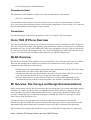
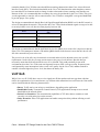
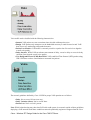
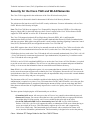
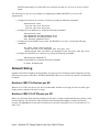
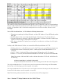
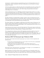
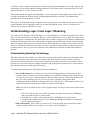
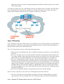
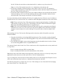
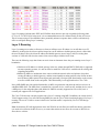
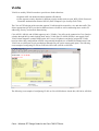
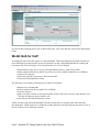
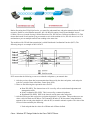
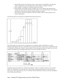
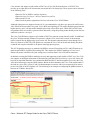
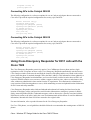
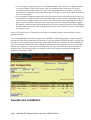
Cisco − Wireless IPT Design Guide for the Cisco 7920 IP Phone
Table of Contents
Wireless IPT Design Guide for the Cisco 7920 IP Phone................................................................................1
Introduction.............................................................................................................................................1
Prerequisites............................................................................................................................................1
Requirements....................................................................................................................................1
Components Used.............................................................................................................................2
Conventions......................................................................................................................................2
Cisco 7920 IP Phone Overview..............................................................................................................2
WLAN Overview....................................................................................................................................2
RF Overview Site Surveys and Design Recommendations................................................................2
VoIP QoS................................................................................................................................................3
Security for the Cisco 7920 and WLAN Networks................................................................................5
Network Sizing.......................................................................................................................................6
Number of 802.11b Devices per AP................................................................................................6
Number of 802.11b IP Phones per AP.............................................................................................6
Numbers of 802.11b Phones per Layer 2 Subnet or VLAN............................................................8
Understanding Layer 2 and Layer 3 Roaming........................................................................................9
Understanding Roaming Terminology.............................................................................................9
Layer 2 Roaming............................................................................................................................10
Layer 3 Roaming............................................................................................................................12
VLANs..................................................................................................................................................13
WLAN QoS for VoIP...........................................................................................................................14
Interconnecting WLANs to Cisco Campus Infrastructure....................................................................18
Connecting APs to the Catalyst 3550 SMI or EMI........................................................................19
Connecting APs to the Catalyst 2950 EI........................................................................................20
Connecting APs to the Catalyst 2950 SI........................................................................................20
Using Cisco Emergency Responder for E911 calls with the Cisco 7920.............................................20
Caveats and Limitations........................................................................................................................21
Call Admission Control..................................................................................................................22
Designing Around the Lack of Layer 3 Roaming..........................................................................22
Other Caveats and Limitations.......................................................................................................22
Related Information..............................................................................................................................23
i
Wireless IPT Design Guide for the Cisco 7920 IP
Phone
Introduction
Prerequisites
Requirements
Components Used
Conventions
Cisco 7920 IP Phone Overview
WLAN Overview
RF Overview Site Surveys and Design Recommendations
VoIP QoS
Security for the Cisco 7920 and WLAN Networks
Network Sizing
Number of 802.11b Devices per AP
Number of 802.11b IP Phones per AP
Numbers of 802.11b Phones per Layer 2 Subnet or VLAN
Understanding Layer 2 and Layer 3 Roaming
Understanding Roaming Terminology
Layer 2 Roaming
Layer 3 Roaming
VLANs
WLAN QoS for VoIP
Interconnecting WLANs to Cisco Campus Infrastructure
Connecting APs to the Catalyst 3550 SMI or EMI
Connecting APs to the Catalyst 2950 EI
Connecting APs to the Catalyst 2950 SI
Using Cisco Emergency Responder for E911 calls with the Cisco 7920
Caveats and Limitations
Call Admission Control
Designing Around the Lack of Layer 3 Roaming
Other Caveats and Limitations
Related Information
Introduction
This document provides design guidelines and deployment recommendations for customers adding the Cisco
7920 IP Phone to an existing Architecture for Voice, Video and Integrated Data (AVVID) network. The
assumption is made that you have either an existing AVVID network for wired IP phones, or that you have
previously read the AVVID design guides. It is not assumed that you have previous Wireless LAN (WLAN)
experience. This document makes reference to several existing design guides for 802.11, IP Telephony, and
campus network design.
Prerequisites
Requirements
Readers of this document should be knowledgeable of the following:
Cisco − Wireless IPT Design Guide for the Cisco 7920 IP Phone
• AVVID design guides and administration.
Components Used
The information in this document is based on the software and hardware versions below:
• The Cisco 7920 IP Phone.
The information in this document was created from the devices in a specific lab environment. All of the
devices used in this document started with a cleared (default) configuration. If your network is live, make sure
that you understand the potential impact of any command.
Conventions
For more information on document conventions, see the Cisco Technical Tips Conventions.
Cisco 7920 IP Phone Overview
The Cisco 7920 IP Phone extends the AVVID family of IP phones from 10/100 Ethernet to 802.11b WLANs.
The Cisco 7920 provides a multi−line appearance with functionality similar to existing Cisco 79xx IP Phones.
In addition, the Cisco 7920 provides enhanced WLAN security and Quality of Service (QoS) for operation in
802.11b networks. Future enhancements to the Cisco 7920 will add support for XML−based data access and
services, as well as Universal Serial Bus (USB) connectivity for additional data services.
WLAN Overview
802.11b WLAN networks allow multiple devices to transmit data, voice, and video at data rates up to 11Mb.
While WLAN networks allow similar types of traffic to be transmitted over them, it does have certain
characteristics that differ from wired networks:
• WLANs operate as a shared medium, which means that communication on the WLAN is half−duplex
and that all devices within a single WLAN share the 11Mb.
• WLAN bandwidth varies based on the distance that a WLAN client is from a WLAN Access Point
(AP). The farther the distance, the lower the data rates that traffic is supported.
• Since all WLAN traffic is seen by all other WLAN devices (within range), additional security
considerations need to be taken to ensure that traffic is not captured or manipulated by intruders.
RF Overview Site Surveys and Design Recommendations
Before getting started with any WLAN deployment, the first activity that every network administrator should
undertake is a complete site survey of the environment where the WLAN devices are deployed. The site
survey should be performed to understand the number of APs required to provide Radio Frequency (RF)
coverage. It should take into consideration which types of antennas provide the best coverage, as well as
where sources of RF interference exist.
An important factor to keep in mind is that rarely do two physical environments have the same RF
characteristics. Because of this, the sections of this document that are RF specific are generalized. Network
administrators may need to adjust those parameters to their specific RF environment and requirements.
While you may have already performed RF site surveys for an initial WLAN deployment, it is important to
Cisco − Wireless IPT Design Guide for the Cisco 7920 IP Phone
remember that the Cisco 7920 has somewhat different roaming characteristics than Cisco Aironet Network
Interface Cards (NICs). This includes thresholds on the Cisco 7920 that determine when the phone roams or
how much the RF environment needs to change in order to determine when a roaming event should occur.
Because of this, it is recommended that a secondary site survey be performed for the Cisco 7920s. This gives
you the opportunity to tune the APs to ensure that the Cisco 7920s have enough RF coverage and bandwidth
to provide proper voice quality.
The design recommendation is that the Received Signal Strength Indication (RSSI) level in the RF network is
at least 20 throughout the network. This provides the Cisco 7920 with the minimum signal coverage to be able
to not only initiate a new call, but also roam properly between APs.
RSSI
15
dBm
−85
30
−70
45
−50
60
−35
The design recommendation is that the QoS Basis Service Set (QBSS) level on the APs is kept lower than 40.
If the Cisco 7920 attempts to initiate a call and the QBSS element in the beacon is more than 40, the call will
fail with a network busy tone to the user.
The power levels of the APs vary from network to network and need to be adjusted to meet site−specific
requirements. On the APs, the coverage area increases as the power levels increase. But this does not
necessarily mean that all the APs should be set to 50 or 100mW. This could potentially create an RF
environment where the Cisco 7920s roam too frequently because of RF coverage overlap. Frequent roams
could potentially cause interruptions in the overall voice quality. On the Cisco 7920, another tradeoff to
consider is that the higher the power−level, the shorter the battery life.
VoIP QoS
While Voice over IP (VoIP) does convert voice signals into IP data packets and converge them with data
traffic, the requirements of voice and data are very different when transmitted over an IP network. Data traffic
can be classified with the following characteristics:
• Bursty Traffic can be sent in large or small bursts, depending on the application.
• Bandwidth Greedy Transmission Control Protocol (TCP) applications attempt to use as much
bandwidth as the network allows.
• Packet Loss Insensitive The retransmission capabilities of TCP allow data to continue to work
correctly even with packet loss on the network.
• Delay Insensitive Most TCP applications can handle some packet delay without effecting overall
performance.
Cisco − Wireless IPT Design Guide for the Cisco 7920 IP Phone
Voice traffic can be classified with the following characteristics:
• Smooth VoIP packets are sent at consistent intervals with uniform packet sizes.
• Benign VoIP packets only attempt to use the bandwidth necessary to send from end to end. VoIP
does not use any windowing to determine data rates.
• Packet Loss Sensitive VoIP traffic is extremely sensitive to packet loss. Excessive loss degrades
overall voice quality.
• Delay Sensitive While VoIP can tolerate some amount of delay, excessive delay or excessive delay
variation (jitter) degrade overall voice quality.
• User Datagram Protocol (UDP) Best Effort VoIP sends Real Time Protocol (RTP) packets using
UDP. UDP does not have a mechanism to retransmit lost packets.
The network guidelines defined by Cisco AVVID for proper VoIP operation are as follows:
• Delay Not to exceed 150 ms (one way).
• Delay Variation (Jitter) Not to exceed 30ms.
• Packet Loss Not to exceed 1 percent.
Note: While isolated testing may show that VoIP calls could operate in a network outside of these guidelines,
deploying a VoIP network under those conditions cannot be predictably engineered. Support from the Cisco
Cisco − Wireless IPT Design Guide for the Cisco 7920 IP Phone
Technical Assistance Center (TAC) (if problems arise) is limited for this situation.
Security for the Cisco 7920 and WLAN Networks
The Cisco 7920 is supported in the architecture of the Cisco Wireless Security Suite.
The architecture is discussed in detail in documents for Wireless LAN Security Solution.
The architecture fits into the overall Cisco SAFE security architecture. For more information, refer to Cisco
SAFE: Wireless LAN Security in Depth.
Note: The Cisco 7920 does not support Cisco Temporal Key Integrity Protocol (TKIP) or Cisco Message
Integrity Check (MIC) in the initial software release. Future versions of the Cisco 7920 software will add
support for TKIP and MIC as well as Wi−Fi Protected Access (WPA).
The Cisco 7920 supports both static Wired Equivalency Protocol (WEP), 802.1, and Extensible
Authentication Protocol (EAP) − Cisco Light Extensible Authentication Protocol (LEAP) for authentication
and data encryption. When either encryption model is used, both the signaling (Signaling Connection Control
Part (SCCP)) and media (RTP) are encrypted between the Cisco 7920 and AP.
Static WEP requires that a 40 or 128 bit key be manually entered on all of the Cisco 7920s as well as the APs.
It performs AP−based authentication based on the device (such as the Cisco 7920) having a matching key.
LEAP allows devices (such as the Cisco 7920 and the AP) to be mutually authenticated (Cisco 7920 > AP, AP
> Cisco 7920) based on a username and password. Upon authentication, a dynamic key is used between the
Cisco 7920 and the AP to encrypt traffic.
If LEAP is used, a LEAP−compliant RADIUS server such as the Cisco Secure ACS for Windows, is required
to provide access to the user database. The ACS server can either store the username and password database
locally, or it can access that information from an external Microsoft Windows directory.
Note: While it is a valid configuration option, it is not recommended that an external (off ACS) database be
used to store the username and password credentials for Cisco 7920 phones. Because the ACS server must be
queried whenever the Cisco 7920 roams between APs, the unpredictable delay to access this external database
could cause excessive delay and poor voice quality.
The placement of the ACS server should be considered when deploying LEAP. This is because LEAP
authentication is required every time a Cisco 7920 roams between APs, and RTP traffic (voice) does not flow
until the LEAP authentication is completed. Reducing the amount of delay (such as router hops and WAN
links) between APs and the ACS significantly improves the overall voice quality when Cisco 7920 users are
roaming..
The three options for deploying the ACS functionality are as follows:
• Centralized ACS server All users access the ACS server in a central location within the network.
• Remote ACS server For remote offices that have slow speed WAN links or congested WAN links
that might delay LEAP processing, a ACS server could be deployed locally in the office.
• Local and Fallback RADIUS server functionality in a Cisco AP In Cisco IOS® Software
Release 12.2(11)JA , the Cisco AP supports the ability to authenticate LEAP users without having to
access an external ACS server. This functionality supports up to 50 users, and is supported for
EAP−Cisco (LEAP) only. This functionality does not interact with a centralized or remote ACS
server in terms of database synchronization. This functionality is designed to be used as the primary
Cisco − Wireless IPT Design Guide for the Cisco 7920 IP Phone
RADIUS functionality in a small office, but could also be used as a ACS server in case of WAN
failure.
The following is a step−by−step example of configuring the fallback RADIUS server for LEAP
authentication:
1. Configure the Network Access Server (NAS), by issuing the following commands:
radius−server local
nas 192.168.10.35 key Cisco
nas 192.168.10.45 key Cisco
2. Configure the user database, by issuing the following commands:
radius−server local
user BM−AP1200−one−SCM password Cisco
user BM−AP1100−two−SCM password Cisco
user testuser password Cisco
3. Configure the local RADIUS server in the APs RADIUS server list, by issuing the following
commands:
aaa group server radius rad_eap
server 192.168.10.45 auth−port 1812 acct−port 1813
radius−server host 192.168.10.45 auth−port 1812 acct−port 1813 key Cisco
4. Configure the RADIUS server timeouts, by issuing the following commands:
radius−server deadtime 10
5. Disable client holdoff, by issuing the following command:
no dot11 holdoff−time
Network Sizing
Outside of normal IP Telephony design guidance for sizing (such as a Public Switched Telephone Network
(PSTN) gateway ports, transcoders, and WAN bandwidth), there are several 802.11b specific considerations
to address.
Number of 802.11b Devices per AP
Between 15 to 25 802.11b devices per AP is recommended. Normal caveats apply in terms of traffic types,
usages patterns, and physical space coverage.
Number of 802.11b IP Phones per AP
Before any discussion about network planning can take place, it helps to understand the basics of the overall
network capacity. The chart below shows the theoretical maximum throughput of an 802.11b WLAN
network. The highlighted sections show the data that is relevant for the packet sizes of VoIP traffic (G.711
and G.729).
Cisco − Wireless IPT Design Guide for the Cisco 7920 IP Phone
One of the key aspects when calculating network capacity for 802.11b networks is that it is a shared medium.
Because of this, consideration must be given for radio contention among the various devices. This means that
the back−off algorithms in 802.11b, that allow multiple devices to access the medium, affect the overall
throughput.
For the VoIP calculations below, a VoIP call has the following characteristics:
1. The packets are made up of a 20 byte IP header, an 8 byte UDP header, a 12 byte RTP header, and the
RTP data.
2. The RTP data is a 20ms voice sample. For G.729, this is 20 bytes. For G.711, this is 160 bytes.
3. The total VoIP packet is 200 bytes of (IP+UDP+RTP) headers + RTP data. The 802.11 header (Layer
2 MAC) is 24 bytes long, so the total packet is 224 bytes.
4. RTP data is transmitted at 50 packets per second (pps) in each direction, or 100pps for a full−duplex
conversation.
Looking at the 11Mb column of the chart, we can make the following calculations for G.711:
• 256 byte packet size = 2,596,588 bits per second = 324,573 bytes per second (Theoretical packet rate)
• 100 packets per second * 224 bytes per packet = 22,400 bytes per second (Bandwidth of a G.711
VoIP call)
• 324,573 / 22,400 = 14.489 calls (Theoretical maximum VoIP capacity per 802.11b channel)
• 14.489 * .6 = 8.69 calls (Theoretical maximum number of VoIP calls * 60 percent of the bandwidth)
Note: Sixty percent of the bandwidth is used to calculate the number of VoIP calls, which allows for
the following:
♦ It allows bandwidth to be available for data traffic.
♦ It provides bandwidth consideration for 802.11b management traffic and acknowledgements.
The design consideration for G.711 calls is not to exceed seven concurrent VoIP calls per AP. This number
has been proven in lab testing to provide acceptable voice quality.
The design consideration for G.729 calls is not to exceed eight concurrent VoIP calls per AP. This number has
been proven in lab testing to provide acceptable voice quality.
Note: The following information affects Voice Activity Detection (VAD) configuration:
Cisco − Wireless IPT Design Guide for the Cisco 7920 IP Phone
All of the above calculations and design recommendations are based on VAD being disabled on the Cisco
7920 IP Phones. VAD is a mechanism in VoIP where no RTP packets are sent if no speech is occurring
during the conversation.
VAD can be enabled on the Cisco 7920 phones and provides some bandwidth conservation, typically around
30 percent. With VAD enabled on the Cisco 7920, it does not use VAD for transmit (Tx) packets, but it
understands what to do on the receive (Rx)−side if VAD is being used by the remote device (such as
understanding the Service ID (SID) bit).
VAD is a global parameter on Cisco CallManager for all phones registered with a specific server or cluster.
And the general design guidance for wired AVVID networks is to disable VAD because it can provide better
overall voice quality. This means that unless the Cisco 7920 phones are going to register to a separate Cisco
CallManager server than wired Cisco 79xx IP Phones, the VAD setting must be the same for all Cisco 79xx
phones.
Beyond determining how much bandwidth is needed for an 802.11b VoIP call, consideration must also be
made for the overall radio contention for a particular RF channel. The general rule is that no more than 15 to
25 802.11b end−points should be deployed per AP. As more end−points are added to an AP, the amount of
overall bandwidth is reduced and transmission delays potentially increase.
The number of phones per AP is dependent on calling patterns of individual customers (Erlang ratios). Cisco
Enterprise Solutions Engineering (ESE) recommends no more than seven calls (concurrent) using G.711, or
eight calls (concurrent) using G.729. Beyond that number of calls, when background data is present, the voice
quality of all calls becomes unacceptable.
Packetization rates for this testing were done with 20ms sample rates. This generates 50pps in each direction.
VAD was disabled during the testing. Using large sample sizes (such as 40ms) could result in a larger number
of simultaneous calls, but it also increases the end−to−end delay of the VoIP calls.
These testing results come from the creation of traffic simulating normal desktop traffic for 15 to 20 users
(such as HTTP, FTP, Simple Mail Transfer Protocol (SMTP), Point of Presence (POP), Telnet 3270
(TN3270)), and then adding incremental Cisco 7920 phones. The number of Cisco 7920s phones added (with
active calls) stopped when the Mean Opinion Scores (MOSs) dropped below the average MOS for G.711 or
G.729 calls on the wired network.
Numbers of 802.11b Phones per Layer 2 Subnet or VLAN
The number of 802.11b phones that should be deployed per Layer 2 subnet or VLAN is dependent on the
following factors:
• No more than 30 APs should be deployed per Layer 2 subnet or VLAN. This is the recommendation
to optimize memory and performance on the APs.
• No more than seven (G.711) or eight (G.729) active calls should be deployed per AP.
• The calling ratio used to determine active versus non−active calls. This is often determined using
Erlang calculators.
Based on these factors, and normal business−class Erlang ratios (3:1 through 5:1), it is recommended not to
exceed 450 to 600 Cisco 7920s per Layer 2 subnet or VLAN.
Note: The limitation of 30 APs per subnet or VLAN is introduced due to new functionality added to Cisco
WLAN clients (such as PCs) and Cisco APs. The functionality is called Secure Fast Roaming, and introduces
a new WLAN architecture that reduces the amount of time it takes a WLAN client to roam between APs. The
Cisco − Wireless IPT Design Guide for the Cisco 7920 IP Phone
30 AP limit is due to memory and processor constraints on the Wireless Domain Server (WDS), which is AP
functionality to provide this enhanced roaming and security. This functionality is introduced into Cisco IOS
Software Release 11.2(11)JA on the Cisco APs.
Deployments that do not require this functionality, or have a physical area that requires more than 30 APs of
coverage, can disable the WDS or Secure Fast Roaming functionality on the APs. This eliminates the
limitation of 30 APs in the subnet or VLAN.
In the future, as WDS functionality is migrated to faster processing devices within the network, the 30 AP per
subnet limitation will be expanded or removed. For more information on this, refer to Cisco Structured
Wireless Aware Network (SWAN) Overview.
Understanding Layer 2 and Layer 3 Roaming
One of the obvious benefits of WLAN IP phones over wired IP phones is the ability to physically move from
place to place while having a conversation. However, unlike cellular phone services, where coverage areas are
usually nationwide or international, WLAN IP phones have smaller coverage areas. In addition, administrators
of WLAN IP phone networks need to understand and consider their IP addressing schemes before deploying
WLAN IP phones. What needs to be considered is how WLAN IP phone coverage overlays with the Layer 2
and Layer 3 addressing within the IP network. An Layer 2 network is defined as being a single IP subnet and
broadcast domain. An Layer 3 network is defined as the combination of multiple IP subnets and broadcast
domains.
Understanding Roaming Terminology
When discussing the term roaming, it is often good to understand the audience and their understanding of the
term. For people that mostly work with voice systems, they often associate roaming with the concept of
physical movement and from where a call can be originated. For people that mostly work with 802.11 data
networks, they also often associate roaming with the concept of physical movement, but they often associate
this with data connectivity while physically moving.
To simplify the terminology, the following two terms are introduced:
• Pre−Call Roaming This is when a user with a Cisco 7920 physically moves from place to place
(within a campus or between sites) before making a voice call. This roaming may be within an Layer
2 VLAN, or across Layer 3 subnet boundaries. If this is within an Layer 2 VLAN, the IP address on
the Cisco 7920 remains the same. If it is across an Layer 3 boundary, and Dynamic Host
Configuration Protocol (DHCP) is enabled on the Cisco 7920, the Cisco 7920 recognizes that it is no
longer in the previous subnet and uses DHCP to obtain a new IP address.
Note: The process by which the Cisco 7920 recognizes that it is no longer in the correct subnet works
as follows:
1. The Cisco 7920 does not received SCCP keepalive messages from the Cisco CallManager
that it is registered with (30 to 90 seconds).
2. It attempts to re−register with an alternate Cisco CallManager (30 to 60 seconds).
3. It realizes that it cannot reach the Cisco CallManager through the IP address and requests a
new IP address using DHCP.
• Mid−Call Roaming This is when a user with a Cisco 7920 physically moves from place to place
(within a campus or between sites) while a voice call is active on the phone.
Cisco − Wireless IPT Design Guide for the Cisco 7920 IP Phone
Note: Any references to roam or roaming throughout the remainder of this document is in the context
of mid−call roaming.
As it relates to roaming, the Cisco 7920 IP Phone currently only supports Layer 2 roaming. This means that a
Cisco 7920 IP Phone can roam between APs that have coverage for a single Layer 2 subnet, but calls are
dropped when the phone roams into the AP coverage for another Layer 2 network.
Layer 2 Roaming
Layer 2 Roaming occurs when a WLAN device, for example the Cisco 7920, physically moves enough that its
radio associates to a different AP. The original and the updated AP offer coverage for the same IP subnet, so
that the WLANs client are still valid after the roam.
The Cisco 7920 performs an Layer 2 roam for the following reasons:
• When the Cisco 7920 initially boots, this is considered a roaming event because it is associating with
a new AP.
• The Cisco 7920 does not receive beacons from the associated AP, and therefore believes that the AP
is no longer available. If three consecutive beacons are not received by the Cisco 7920, and its unicast
packet to the AP is not acknowledged, the Cisco 7920 begins the roaming process to another AP.
• The Cisco 7920 periodically scans for better APs. Because the initial startup is considered to be a
roaming event, all client stations have roamed at least once. After the roam process has completed, the
client station maintains the list of eligible roam targets. When all AP information is received (channel
update, current AP update), the phone evaluates its current AP with the list of eligible roam targets. If
conditions change on the current AP (RSSI low or QBSS high) so that one of the APs in the client's
stored list now appears to be a better choice than the current AP, the phone starts a handoff procedure
to associate with the AP.
• The Service Set Identifier (SSID) or encryption type on the Cisco 7920 has changed.
Once one of the events above occurs, the Layer 2 roaming process proceeds as follows:
1. The Cisco 7920 looks at its list of eligible roam targets (APs with a matching SSID or encryption
type) and chooses the best candidate. The Cisco 7920 then attempt to associate and authenticate to
Cisco − Wireless IPT Design Guide for the Cisco 7920 IP Phone
this AP. If either the association or authentication fails, it continues to try the next best AP.
Note: As a Cisco 7920 roams between APs, it re−authenticates with each new AP.
2. AP B sends a null MAC multicast using the source address of the Cisco 7920. This updates the
Content Addressable Memory (CAM) tables in upstream switches and directs further LAN traffic for
the Cisco 7920 to AP B, and not AP A.
3. AP B sends a MAC multicast using its own source address telling the old AP that AP B now has the
client associated to it. AP A receives this multicast and removes the client MAC address from its
association table. This message uses the Inter−AP Protocol (IAPP).
In trying to determine potential candidate APs for Layer 2 roaming, the Cisco 7920 uses several variables to
determine the best AP to associate with. The variables are RSSI and QBSS. Definitions of these terms follow:
• RSSI This is used by the Cisco 7920 to determine the signal strength and quality of available APs
within an RF coverage area. The Cisco 7920 attempts to associate with the AP that has the highest
RSSI value (and matching authentication or encryption Type).
• QBSS This is a beacon Information Element (IE) that allows the AP to communicate the Channel
Utilization (CU) to the Cisco 7920. The Cisco 7920 uses the QBSS value to determine if it should
attempt to roam to another AP, as APs with high CU may not be able to effectively handle VoIP
traffic.
When roaming, the Cisco 7920 uses the following model to determine which AP should be used as the
handoff candidate:
1. Determine which APs are advertising QBSS in their beacons. These should be considered handoff
candidates before APs that are not advertising QBSS. If any of these meet the threshold criteria, begin
the roaming process.
2. If no APs advertise QBSS, or those advertising do not meet the threshold criteria, look for APs that
are not advertising QBSS but have acceptable RSSI levels.
The amount of time it takes for the Cisco 7920 to roam between APs is dependent on the security model used
(average times):
• Layer 2 roaming with static WEP: less than 100ms.
• Layer 2 roaming with LEAP (local ACS authentication): 200 to 400ms
Note: Delay times with LEAP could be longer than 200 to 300ms if the ACS server is heavily used by other
applications (such as remote access dial−up or VPN, or TACACS authentication).
Layer 2 roaming time is the time between the last RTP packet seen on AP1 and the first RTP packet seen on
AP2. It also includes the times it takes to re−authenticate and reassociate with AP2.
The following image shows a sample trace of a Cisco 7920 roaming to a new AP and the LEAP messaging
that is between the Cisco 7920 and the AP:
Cisco − Wireless IPT Design Guide for the Cisco 7920 IP Phone
Layer 2 roaming with both static WEP and LEAP has been shown to provide acceptable QoS using either
G.711 or G.729. If LEAP is being used, it is recommended that users are defined locally on the ACS server.
This is because using off−box databases have potentially unknown response times, which could adversely
effect overall QoS during Layer 2 roaming.
Layer 3 Roaming
Layer 3 roaming occurs when a client moves from an AP that covers IP subnet A to an AP that covers IP
subnet B. At this point, the client would no longer have an IP address or default gateway that is valid within
the new IP subnet. Since the clients IP address and default gateway are no longer valid, its existing data
sessions or VoIP calls fail since the remote client can no longer reach the local client.
There are the following ways that clients can work in an environment where they are roaming across Layer 3
boundaries:
• Obtain a new IP address or default gateway in the new subnet through DHCP. While this is supported
on some operating systems, it is not an effective model for VoIP since it would break all existing calls
(signaling and media).
• Mobile IP (MIP) is a mechanism where routers within the network allow end points to keep their
existing IP address or default gateway, and the routers handle rerouting packets to the clients on their
new IP subnet. MIP requires Home Agent and (optionally) Foreign Agent functionality on the routers,
as well as a MIP client on the end points. This functionality is not supported on the Cisco 7920.
Proxy MIP (PMIP) provides similar functionality to MIP, except that the end points do not have to have an
embedded MIP client. The MIP client is contained in a network device, such as an AP, and that device acts as
a MIP proxy for the end points that reside behind it. PMIP is currently supported on Cisco APs, but it is
currently not supported for VoIP applications.
The Cisco 7920 does not currently support native Layer 3 roaming using MIP. In addition, the current lack of
VLAN support on the Cisco APs when using PMIP prevents the Cisco 7920s from being deployed for Layer 3
roaming. The use of VLANs to create isolated voice and data traffic is required by Cisco AVVID design
guidelines.
Note: In multistory WLAN deployments where the WLANs on each floor have different subnets, particular
care needs to be taken in the RF site survey to ensure that stations on one floor do not roam to WLANs on
floors above or below.
Cisco − Wireless IPT Design Guide for the Cisco 7920 IP Phone
VLANs
VLANs are used by WLAN networks to provide two distinct functions:
• Segment traffic into distinct broadcast domains (IP subnets).
• Create separate security domains for different security models (such as open, WEP, LEAP, Protected
Extensible Authentication Protocol (PEAP), EAP Transport Layer Security (EAP/TLS))
The Cisco AVVID design guide states that separate VLANs should be created for voice and data traffic. This
allows appropriate QoS to be provided to different classes of traffic as well as addressing issues such as IP
addressing, security, and network dimensioning.
Cisco AP350, AP1100, and AP1200 support up to 16 VLANs. Cisco APs can be connected to Cisco Catalyst
switches through 802.1q trunks (hybrid mode: native VLAN (Port VLAN ID (PVID)) is not tagged). Each
VLAN is then mapped to a unique SSID on the AP. Users (or IP phones) can then be assigned to VLANs
based on either static configuration of SSID or dynamically though the use of RADIUS authentication. Each
VLAN can use a different security mechanism, although only one can be unencrypted (open). The following
is an example of configuring VLANs on VxWorks−based APs (AP350 or AP1200):
The following is an example of configuring VLANs on Cisco IOS Software−based APs (AP1100 or AP1200):
Cisco − Wireless IPT Design Guide for the Cisco 7920 IP Phone
For more details on deploying VLANs in WLAN networks, refer to the Wireless Virtual LAN Deployment
Guide.
WLAN QoS for VoIP
As mentioned earlier, WLANs operate as a shared medium. This means that QoS on WLAN networks are
more difficult than wired networks because end points do not have dedicated bandwidth for sending and
receiving traffic. The following is a list of characteristics of a wired VoIP QoS:
• Dedicated access per user or device (switched ethernet, Point−to−Point (P2P) WAN).
• Packets marked with 802.1p and IP Type of Service (ToS) or Differentiated Services (DiffServ).
• Can provide hard QoS.
• QoS can be applied to upstream or downstream traffic.
• Can provide hard admission control.
The following is an example of characteristics of WLAN VoIP QoS:
• Shared access to bandwidth.
• Packets marked with 802.1p and IP ToS or DiffServ.
• Provides soft QoS.
• QoS is currently available to downstream traffic from the AP, but few devices other than the Cisco
7920 provide upstream QoS toward the AP.
• Can only provide limited admission control.
Unlike networks with dedicated bandwidth, WLAN networks have to consider traffic direction when
discussing QoS. Traffic needs to be considered as either upstream or downstream from the point of view of
the AP, as shown in the following example:
Cisco − Wireless IPT Design Guide for the Cisco 7920 IP Phone
Before discussing how WLAN QoS works, you must first understand how end points transmit data on WLAN
networks. Similar to wired Ethernet networks, 802.11b WLANs employ Carrier Sense Multiple Access
(CSMA). However, instead of using Collision Detection (CD), WLANs use Collision Avoidance (CA). This
means that instead of each station trying to transmit as soon as the medium is free, WLAN devices use a CA
mechanism to prevent multiple stations from sending at the same time.
The model used for WLAN data transmission is called Distributed Coordination Function (DCF). The
following image is an example of 802.11b DCF:
DCF ensures that the following events occur when the end points try to transmit data:
1. After the previous frame has been transmitted and detected by the other end points, each end point
waits for a period of time called Inter−Frame Space (IFS).
2. There are the following three potential values for IFS:
♦ Short IFS (SIFS) The shortest interval. It is used by APs to send acknowledgements and
management traffic.
♦ Point Coordination IFS (PIFS) This is not used by commercial products.
♦ Distributed IFS (DIFS) DIFS is the interval used by most other end points.
3. After the IFS interval has expired, the end points begin their CA procedure. This procedure uses two
values, called aCWmin and aCWmax. The Contention Window (CW) determines what additional
amount of time an end point should wait, after the IFS, to attend to transmit a packet. The value of the
CW used is determined by the following:
1. Each end point has the values for aCWmin and aCWmax defined.
Cisco − Wireless IPT Design Guide for the Cisco 7920 IP Phone
2. After the IFS expires, the end point selects a value between 0 and aCWmin. The end point
waits the length of this value and determines if the medium is available to transmit.
3. If the medium is available, the end point transmits the packets.
4. If the medium is unavailable (such as if another device sent a packet), the end point waits
until the end of the packet transmission (from another device) and the IFS period. In addition,
it doubles the value chosen in Step 2 and then attempts to transmit.
5. The end point continues to double the value from b until it either reached aCWmax or the
packet is transmitted.
The following shows the growth in the random backoff range with retries:
For WLAN QoS, Cisco APs and Cisco 7920 phones use a technique similar to IEEE 802.11e, called
Enhanced DCF (EDCF). EDCF is a model that allows end devices that have delay sensitive multimedia traffic
to modify their aCWmin and aCWmax values to allow for statically greater (and more frequent) access to the
medium. The following is an example of how EDCF works on Cisco WLAN devices:
By default, end points usually have aCWmin and aCWmax values of 31 and 255, respectively, for all data
traffic. For VoIP traffic, Cisco APs and Cisco 7920s set the aCWmin and aCWmax to values of 3 and 31,
respectively. This is equivalent to CoS of 6. Cisco IOS Software based APs can also vary the IFS (in addition
to the aCWmin and aCWmax).
Cisco − Wireless IPT Design Guide for the Cisco 7920 IP Phone
Cisco Aironet APs support a QoS similar to EDCF as of Cisco IOS Software Release 12.0T SW. This
provides up to eight queues for downstream (toward the 802.11b clients) QoS. These queues can be allocated
in the following ways:
• Based on ToS or DiffServ settings of packets.
• Based on Layer 2 or Layer 3 Access Control Lists (ACLs).
• Based on the VLAN.
• Based on the dynamic registration of devices such as the Cisco 7920 IP Phone.
Although eight queues are supported on the AP, it is recommended to only have two queues for traffic on the
AP to ensure the best possible voice QoS. Voice (RTP) and signaling (SCCP) traffic should be placed into the
highest priority queue. All data traffic should be placed into a best effort queue. While 802.11b EDCF does
not guarantee that voice traffic is protected from data traffic, using this queuing model should provide the best
statistical results for voice QoS.
The Cisco 7920 IP Phones support a QoS similar to EDCF for upstream (toward the AP) traffic. In additional,
the Cisco 7920 dynamically announces its presence with the Cisco Aironet AP to ensure its downstream
traffic is placed into the high priority queue on the AP. This dynamic announcement is done through Cisco
Discovery Protocol (CDP). The CDP packets are sent from the Cisco 7920 to the AP and identify the phone
so that the AP can place all traffic to the phone in the high priority queue.
The SCCP signaling messages are marked with DiffServ Assured Forwarding (AF)31, and RTP packets are
marked with DiffServ Expedited Forwarding (EF). This matches the DiffServ markings of Cisco wired
Ethernet IP phones, and allows the QoS settings to be consistent from LAN to WLAN environments.
In addition to setting the DiffServ markings correctly and supporting a QoS similar to EDCF, the Cisco 7920
also supports an intelligent mechanism to determine the QoS that can be provides by a given AP. It does this
based on an algorithm that takes into consideration RSSI and RF CU based on updates received by the Cisco
AP in beacon messages using the QBSS element. Based on this information, the Cisco 7920 can determine if
the load on a given AP is excessive and if it should attempt to associate with a less congested AP in order to
preserve the QoS of an IP Telephony call. The following is an example of configuring the QBBS element in
beacons on VxWorks−based APs:
Cisco − Wireless IPT Design Guide for the Cisco 7920 IP Phone
The following is an example of configuring the QBBS element in beacons on Cisco IOS Software−based APs:
Beyond just having queuing and setting packets with the correct DiffServ markings, delay and jitter need to be
taken into consideration. This is especially true for upstream traffic since there is no queuing among clients on
the 802.11b side of the AP. The simplest way to accomplish this is to stay within the guidelines for the
number of WLAN clients per AP. Exceeding this creates additional opportunities to introduce packet delay
and jitter.
For more details about deploying QoS in WLAN networks, refer to the Wireless Quality−of−Service
Deployment Guide.
Interconnecting WLANs to Cisco Campus Infrastructure
This section contains pre−tested, recommended configurations. This helps you to quickly and simply build
and deploy a Cisco approved network design using Catalyst 3550 and 2950 series Intelligent Ethernet
Switches.
By following the information in this section, you can create a Cisco AVVID Network Infrastructure to run
converged voice, video, and data network over IP, with due consideration for QoS, bandwidth, latency, and
high performance in demand by Cisco AVVID Network Infrastructure solutions.
The AP template should be configured when a single AP is attached to a port. This template adds all the
baseline security and resiliency features of the standard desktop template, but for the Catalyst 3550, it also
optimizes the performance of the attached AP.
Ethernet switch ports can transmit and receive at 100Mbps. However, APs, depending on the type (802.11b),
only have a practical throughput of 6Mbps or less. This throughput mismatch means that with a burst of
traffic, the AP needs to do packet drops, which adds an excessive processor burden to the unit and affects
performance.
By taking advantage of the Catalyst 3550 policing and rate limiting capabilities, the task of dropping
excessive packets is removed from the AP. This template rate limits the port to the practical throughput of 6M
and guaranteeing 1Mbps for high priority voice and control traffic. Because of this prioritization, this template
can be used with wireless IP telephones.
The 3550−24−PWR in−line power switch can be used to provide power to the AP.
This template helps create a secure and resilient network connection with the following features:
• Return Port Configurations to Default Prevents configuration conflicts clearing any pre−existing
port configurations. This allows you to start with a clean slate.
• Disable Dynamic Trunking Protocol (DTP) Disables trunking, which is not needed for a
connection to an AP.
Cisco − Wireless IPT Design Guide for the Cisco 7920 IP Phone
• Disable Port Aggregation Protocol (PagP) − PagP is enabled by default, but it is not needed for
user−facing ports.
• Enable Port Fast Allows a switch to quickly resume forwarding traffic if a Spanning Tree Protocol
(STP) link goes down.
• Configure Wireless VLAN Creates a unique wireless VLAN that isolates wireless traffic from
other data, voice, and management VLANs, thereby isolating traffic and ensuring greater control of
traffic.
• Enable QoS, and Do not Trust the Port (mark down to 0) Ensures appropriate treatment of high
priority traffic, including soft phones, and prevents users from consuming excessive bandwidth by
re−configuring their PCs.
Connecting APs to the Catalyst 3550 SMI or EMI
The following configuration is a reference template for use on Catalyst switch ports that are connected to
Cisco APs. It provide the required configurations for security, QoS, and STP:
default interface <xx/yy>
switchport mode access
spanning−tree bpduguard [enable]
spanning−tree bpdufilter [enable]
no channel−protocol
spanning−tree portfast
vlan [vlan id]
mls qos
auto qos voip trust
mls qos map cos−dscp 0 10 18 26 34 46 48 56
mls qos aggregate−police AGG−POL−5M−DEFAULT 5000000 8000 exceed−action drop
class−map match−any EGRESS−DSCP−0
match ip dscp 0
class−map match−any EGRESS−DSCP−10
match ip dscp 10
class−map match−any EGRESS−DSCP−56
match ip dscp 56
class−map match−any EGRESS−DSCP−26
match ip dscp 26
class−map match−any EGRESS−DSCP−18
match ip dscp 18
class−map match−any EGRESS−DSCP−48
match ip dscp 48
!
policy−map EGRESS−POLICING
class EGRESS−DSCP−0
police aggregate AGG−POL−5M−DEFAULT
class EGRESS−DSCP−10
police aggregate AGG−POL−5M−DEFAULT
class EGRESS−DSCP−18
police aggregate AGG−POL−5M−DEFAULT
class EGRESS−DSCP−34
police aggregate AGG−POL−5M−DEFAULT
class EGRESS−DSCP−48
police aggregate AGG−POL−5M−DEFAULT
class EGRESS−DSCP−56
police aggregate AGG−POL−5M−DEFAULT
!
interface [interface id]
description 11m Towards Wireless Access Point
no ip address
mls qos monitor dscp 0 10 18 26 34 46 48 56
service−policy output EGRESS−POLICING
Cisco − Wireless IPT Design Guide for the Cisco 7920 IP Phone
wrr−queue cos−map 4 5
priority−queue out
Connecting APs to the Catalyst 2950 EI
The following configuration is a reference template for use on Catalyst switch ports that are connected to
Cisco APs. It provide the required configurations for security, QoS, and STP:
default interface <xx/yy>
switchport mode access
spanning−tree bpduguard [enable]
spanning−tree bpdufilter [enable]
no channel−protocol
spanning−tree portfast
vlan [vlan id]
auto qos voip trust
Connecting APs to the Catalyst 2950 SI
The following configuration is a reference template for use on Catalyst switch ports that are connected to
Cisco APs. It provide the required configurations for security, QoS, and STP:
default interface <xx/yy>
switchport mode access
spanning−tree bpduguard [enable]
spanning−tree bpdufilter [enable]
no channel−protocol
spanning−tree portfast
vlan [vlan id]
Using Cisco Emergency Responder for E911 calls with the
Cisco 7920
The Cisco Emergency Responder proactively queries Cisco CallManager for new phone and user login
registration events. In response to these events, Cisco Emergency Responder automatically searches known
Cisco Catalyst switches in the network and finds the location of the phone and the user, based on the switch
port to which the phone is attached (through CDP or the MAC address). This information is then updated in a
Cisco Emergency Responder location database, and is used to identify a callers location when an E911 call
is placed. With this solution, users can move within a campus or between sites, wherever and whenever they
want, without any administrative intervention from the IT organization. This eliminates the administrative
costs associated with relocating phones or users, while maintaining accurate and updated location information
for E911 state and safety mandates.
Cisco Emergency Responder makes informed inbound and outbound call routing decisions based on the
location of emergency callers, and provides crucial location information to emergency operators in Public
Safety Answering Points (PSAPs). Outbound emergency calls are directed to a gateway associated with the
PSAP that is nearest to the caller, and in the event of an unintentional call disconnect or need for additional
information, inbound calls from a PSAP are returned to the original caller.
For more information, refer to product literature for the Cisco Emergency Responder.
For Cisco 7920 phones, several guidelines should be followed to accommodate the roaming nature of 802.11b
phones.
Cisco − Wireless IPT Design Guide for the Cisco 7920 IP Phone
• Cisco Emergency Responder can query for IP Phones through either CDP (on the Catalyst switches)
or the MAC address. Since CDP is sent as a link−layer multicast and is used by the Cisco AP to
determine the QoS settings for the Cisco 7920, it is not propagated up to the Catalyst switch. This
means that Cisco Emergency Responder should query the Catalyst switches for the MAC addresses of
the Cisco 7920 phones.
• Cisco Emergency Responder groups devices into Emergency Response Locations (ERL) so they can
be identified by a physical location (such as building, floor, or region of floor). Depending on how the
power levels are configured on the Cisco APs, it is possible that the signal could propagate to floors
above or below the actual AP that the Cisco 7920 is associated with. Using antennas that propagate
RF signal in a more horizontal pattern helps alleviate this, but emergency personnel within a building
should be made aware of this when organizing their searches for the individual or device that initiated
the emergency call.
An E911 coverage policy is an individual decision that each company needs to make and adapt it to their
physical locations.
It is recommended that each AP been assigned to its own ERL (or minimally grouping a couple of adjacent
APs into one ERL). This has the benefit of allowing on−site, and potentially PSAP personnel, to identify that
the caller is using a wireless device (by using a code or abbreviation in the Automatic Location Information
(ALI) or switch port location field). This is important information for first responders because it means that
adjacent floors, hallways, rooms, and even buildings may need to be searched to locate an unconscious or
incapable caller. The following image is an example of the Cisco Emergency Responder's configuration
Graphical User Interface (GUI):
Caveats and Limitations
Cisco − Wireless IPT Design Guide for the Cisco 7920 IP Phone
Call Admission Control
Call Admission Control (CAC) provides the mechanism that prevents the presence of the next voice call to
interrupt or provide poor QoS for all existing voice calls. Regarding Time−Division Multiplex (TDM), this is
accomplished by a finite number of DS0 channels. In wired Ethernet AVVID networks, this is provided by an
interaction between the Cisco CallManager regions and Cisco H.323 gatekeepers. However, these
mechanisms only address CAC for the initial setup of IP Telephony calls. They do not address CAC when the
underlying network is changing for the IP phone throughout the call. This is the case when a Cisco 7920
roams between two APs.
While the Cisco APs does send out QBSS information about the CU, and the Cisco 7920 can utilize this
information to determine the best AP to associate with, this does not provide a 100 percent guarantee that calls
retain proper QoS during a roam between APs. One example of when this degraded QoS could occur is an
event that causes more than seven or eight active Cisco 7920s to roam into an area served by a single AP, thus
exceeding the guidelines for calls per AP.
If the CU is above the CU threshold, the call is not setup and the phone displays a network busy
message. If the CU of the candidate handoff AP is above the threshold, the Cisco 7920 remains associated
to the existing AP for as long as possible. Once the current AP is lost (no probe response or beacons received),
the Cisco 7920 handsoff to the candidate AP regardless of the CU. A beep is heard before this happens so the
user can go back toward the current AP or stop and finish the conversation.
Another area of admission control that needs to be considered with the Cisco 7920 is when a user takes the
Cisco 7920 from one location to another (such as campus to branch). When the Cisco 7920 re−registers with
the Cisco CallManager, there is no mechanism that updates which Cisco CallManager region (or gatekeeper
zone) the Cisco 7920 is associated with. This means that it is possible that calls to or from that Cisco 7920
would not properly be accounted for across a WAN link, and could cause poor voice quality to phones that are
registered in that region.
Designing Around the Lack of Layer 3 Roaming
For customers that require roaming support for a large area (such as between floors of a buildings), large
Layer 2 VLANs (spanning across access switches) can be created to eliminate the Cisco 7920s crossing an
Layer 3 boundary when roaming. The following guidelines need to be considered for customers that are
looking to deploy large Layer 2 VLANs:
• Cisco ESE guidelines do not recommend that data VLANs span multiple access switches.
• An Layer 2 VLAN should not cross a building boundary. If this is required, then an additional
(overlay) Layer 2 core needs to be built to avoid creating instability and excessive traffic in the
traditional Layer 3 core.
• Both the voice VLAN and the native VLAN on the AP need to be trunked across the large Layer 2
VLAN. This is required to allow both voice traffic and IAPP traffic between the APs.
• Having Layer 2 VLANs span multiple access switches creates the possibility of STP loops (if
configured incorrectly) and overall network instability. Designs using this should model should be
reviewed with your Cisco Systems Engineer before deployment.
• For customers that may eventually be considering extending their Layer 3 networks down to the
access switches, the model of building large Layer 2 VLANs is no longer valid.
Other Caveats and Limitations
The following are other things to be aware of regarding the Cisco 7920 IP Phone:
Cisco − Wireless IPT Design Guide for the Cisco 7920 IP Phone
• Cisco 7920 does not support network−based directories. This will be supported in future software
releases.
• Cisco 7920 does not support XML−based applications. This will be supported in future software
releases.
Related Information
• Voice Technologies
• Voice, Telephony and Messaging Devices
• Voice Software
• Voice, Telephony and Messaging TAC eLearning Solutions
• Recommended Reading: Troubleshooting Cisco IP Telephony
• Technical Support − Cisco Systems
All contents are Copyright © 1992−2003 Cisco Systems, Inc. All rights reserved. Important Notices and Privacy Statement.
Cisco − Wireless IPT Design Guide for the Cisco 7920 IP Phone