1
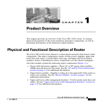
C H A P T E R
1
Product Overview
This chapter provides an overview of the Cisco 12006 and Cisco 12406 series
routers. It contains physical descriptions of the router hardware and major
components, and functional descriptions of the hardware-related features.
Introduction
The routers described in this guide are part of the Cisco 12006 and Cisco 12406
series routers and include:
•
The original Cisco 12006 and Cisco 12406 series routers.
•
The Cisco 12006 and Cisco 12406 enhanced series routers. The enhanced
series of routers use higher capacity power supplies, a more powerful blower
module, and have a new front door.
Note
Most illustrations are shown without the new front door for clarity.
Cisco 12006 and Cisco 12406 Router Installation and Configuration Guide
OL-11497-03
1-1
Chapter 1
Product Overview
Product Description
These two router models are differentiated by the switching capacity of the switch
fabric installed in the router:
•
Cisco 12006 Router—2.5-Gbps switch fabric
•
Cisco 12406 Router—10-Gbps switch fabric
Other than their various capacities, these routers are almost identical. Differences
between each router are described unless otherwise noted, all information in this
publication applies to all routers.
Product Description
The Cisco 12006 and Cisco 12406 routers, shown in Figure 1-1, are members of
the Cisco 12000 series router family. These routers are aimed at scaling the
Internet and enterprise backbones to speeds of 155 Mbps (OC-3/STM-1),
622 Mbps (OC-12/STM-4), 2.4 Gbps (OC-48/STM-16), and 10 Gbps
(OC-192/STM).
Cisco 12006 and Cisco 12406 Router Installation and Configuration Guide
1-2
OL-11497-03
Chapter 1
Product Overview
Product Description
Figure 1-1
Cisco 12006 and Cisco 12406 router (Front View)
1
2
8
3
T
EC
EJ
-1
OT
SL
-0
OT
SL
T
SE
RE
X
AU
E
LL
CO RX
OL
NS
-45
RJ
CO
K
LIN
TX
I
MI
GIGABIT
ROUTE
PROCESSO
R
CISCO 120
00
GIGABIT
SWIT
SERIES
CH ROU
TER
101344
7
6
4
5
1
Line card slots (five)
5
Alarm card slots (two)
2
RP slot
6
Power module bays (two)
3
Blower module
7
CSC slots (two)
4
SFC slots (three)
8
Cable-management bracket
With a chassis height of 18.5 inches (46.9 cm), four Cisco 12006 and
Cisco 12406 routers can be installed in a single standard 7-foot (2.15-m)
equipment rack.
Cisco 12006 and Cisco 12406 routers support system software downloads for
most Cisco IOS software upgrades, which enables you to remotely download,
store, and boot from a new Cisco IOS image.
Cisco 12006 and Cisco 12406 Router Installation and Configuration Guide
OL-11497-03
1-3
Chapter 1
Product Overview
Product Description
Cisco 12006 and Cisco 12406 routers have the following key features:
•
Route Processor (RP)—Slot 5 (bottom slot) is the recommended slot for the
first RP. When the router is equipped with a redundant RP, it can be installed
in any of the five regular line card slots.
•
Line Cards—Up to five OC-192 line cards, four if redundant RPs are
installed. These slots support the online insertion and removal (OIR) feature
so installed cards are hot-swappable: A failed card can be removed and
replaced with the router powered on.
•
Clock and Scheduler Cards (CSCs) and Switch Fabric Cards (SFCs)—Two
dedicated hot-swappable slots for CSCs; three dedicated hot-swappable slots
for SFCs.
Note
The Cisco 12006 Router uses 2.5-Gbps switch fabric; the
Cisco 12406 Router uses 10-Gbps switch fabric. You cannot mix
2.5-Gbps switch fabric cards and 10-Gbps switch fabric cards in a
chassis. The router will not operate with a mix of switch fabric card
types.
Note
When operating your router with a single CSC, the second CSC slot
must have a CSC blank filler (MAS-GSR6-CSCBLNK=) installed to
ensure EMI compliance.
•
Two dedicated alarm card slots (for 1+1 redundancy)
•
Alarm and Illumination—Alarm and illumination for operating ranges in the
card cage, clock and scheduler card, and switch fabric card bays.
•
Two hot-swappable AC-input power supplies or DC-input power entry
modules (PEMs).
Note
When operating your router on a single AC-input power supply or
DC-input PEM, the second power module bay must have a blank filler
(MAS-GSR-PWRBLANK=) installed to ensure EMI compliance.
Cisco 12006 and Cisco 12406 Router Installation and Configuration Guide
1-4
OL-11497-03
Chapter 1
Product Overview
Product Description
•
All power modules and other field replaceable units (FRUs), except for the
air blower module and the power distribution unit (PDU), can be removed
from the front of the chassis.
•
All source power connections are located at the rear of the chassis on the
PDU. (See Figure 1-2.)
•
Enhanced models have a new stylish front door that hides router cabling. The
door can be installed to open from the right side or left side to give you total
flexibility.
•
Network Equipment Building Systems—Cisco 12006 and Cisco 12406
routers comply with the Network Equipment Building System (NEBS)
Criteria Level 3 requirements defined in SR-3580 for flammability,
structural, and electronics compliance.
•
Electromagnetic Compatibility and Electrostatic Discharge Compliant—
Cisco 12006 and Cisco 12406 routers comply with emissions, immunity, and
electrostatic discharge (ESD) standards for both product and packaging.
•
Bonding and Grounding—Bonding and grounding for safety, circuit
protection, noise currents, reliability, and operations compliance.
•
Environmental Monitoring—Cisco 12006 and Cisco 12406 router complies
with environmental monitoring standards for operating temperature and
humidity, as well as handling temperature and humidity (except for heat
dissipation).
•
Shock and Vibration—Cisco 12006 and Cisco 12406 routers have been
shock- and vibration-tested for operating ranges, handling, and earthquake
standards to NEBS (Zone 4 per GR-63-Core). These tests have been
conducted in earthquake environment and criteria, office vibration and
criteria, transportation vibration and criteria, and packaged equipment shock
criteria.
Cisco 12006 and Cisco 12406 Router Installation and Configuration Guide
OL-11497-03
1-5
Chapter 1
Product Overview
Product Description
Figure 1-2
Cisco 12006 and Cisco 12406 router (Rear View)
1
3
4
101114
HIGH SPEE
D BLOWER
2
5
1
Blower module
4
Air exhaust vents
2
Blower module LEDs
5
PDU (behind Blower module; AC
PDU shown)
3
Blower module handle
–
–
•
Fiber Cable Management—Fiber cable management with support for
high-density fiber Fast Ethernet (FE) ports.
•
Current 1.275-inch pitch line cards will fit in the line card cage with the
addition of a front panel adapter cover. The line card adapter cover is included
with the 1.275-inch line card.
Cisco 12006 and Cisco 12406 Router Installation and Configuration Guide
1-6
OL-11497-03
Chapter 1
Product Overview
Physical and Functional Description
Physical and Functional Description
The main physical components of Cisco 12006 and Cisco 12406 routers and their
functions are described in the following sections:
•
Chassis, page 1-7
•
Multigigabit Crossbar Switch Fabric, page 1-10
•
Maintenance Bus, page 1-13
•
Route Processors, page 1-15
•
Line Cards, page 1-33
•
Alarm Cards, page 1-35
•
Power Subsystems, page 1-37
•
Blower Module, page 1-47
•
Air Filters, page 1-49
•
Cable-Management System, page 1-50
Chassis
The Cisco 12006 and Cisco 12406 router chassis is an enclosure that consists of
two integral card cages and two power module bays. (see Figure 1-1.)
RP and Line Card Slots
The RP and line card cage has six user-configurable slots that support one RP and
up to five line cards. Network interfaces reside on the line cards that connect the
switch fabric of the router to the external networks. For more information about
the role of the RP, see the “Route Processors” section on page 1-15. For more
information about the role of the line cards, see the “Line Cards” section on
page 1-33.
Note
Cisco 12006 and Cisco 12406 routers use line cards that are compatible with
other Cisco 12000 series routers.
Cisco 12006 and Cisco 12406 Router Installation and Configuration Guide
OL-11497-03
1-7
Chapter 1
Product Overview
Chassis
Switch Fabric Card Slots
The switch fabric circuitry resides in five fabric card slots: two for CSCs and three
for SFCs. (See Figure 1-1.) For more information about the role of the switch
fabric circuitry, see the “Multigigabit Crossbar Switch Fabric” section on
page 1-10.
Alarm Card Slots
Cisco 12006 and Cisco 12406 routers are equipped with two alarm cards. These
cards are positioned beside one another and occupy two card slots directly under
the CSC slots. (See Figure 1-1.) For more information about the role of the alarm
cards, see the “Alarm Cards” section on page 1-35.
Note
The two alarm cards occupy slots under the two CSC slots in the CSC card cage,
but are not part of the switch fabric.
Chassis Backplane
All of the card cages are tied together electrically through a passive system
backplane in the back of the chassis. Nearly all of the wiring and circuitry in the
chassis is contained within or connected to the chassis backplane. The chassis
backplane distributes DC power to all of the cards in the chassis as well as the
blower module, and provides the physical communication pathway between
cards, both for network data and system communication across the internal system
maintenance bus (MBus).
Cisco 12006 and Cisco 12406 Router Installation and Configuration Guide
1-8
OL-11497-03
Chapter 1
Product Overview
Chassis
Power
Because a Cisco 12006 or Cisco 12406 Router can be configured with either an
AC-input power system or a DC-input power system, the power module bays will
accept either AC-input power supply modules or DC-input PEMs. For more
information about the power subsystems, see the “Power Subsystems” section on
page 1-37.
Caution
To ensure that the chassis configuration complies with the required power
budgets, use the on-line power calculator. Failure to properly verify the
configuration may result in an unpredictable state if one of the power units fails.
Contact your local sales representative for assistance.
Cooling
Cisco 12006 and Cisco 12406 routers are equipped with a blower module to
distribute air within the chassis. The blower module is a removable module
located on the rear of the chassis. (See Figure 1-2.) For more information about
the blower module, see the “Blower Module” section on page 1-47.
Cisco 12006 and Cisco 12406 Router Installation and Configuration Guide
OL-11497-03
1-9
Chapter 1
Product Overview
Multigigabit Crossbar Switch Fabric
Multigigabit Crossbar Switch Fabric
Cisco 12006 and Cisco 12406 router switch fabric circuity provides synchronized
gigabit-speed interconnections for the line cards and the RP. The switch fabric
circuitry resides in five fabric card slots: two for CSCs; three for SFCs. (See
Figure 1-3.)
Figure 1-3
Clock and Scheduler and Switch Fabric Card Bays
T
EC
EJ
-1
OT
SL
-0
OT
SL
T
SE
RE
X
AU
E
OL
NS
CO
LL
CO RX
K
LIN
CSC
CISCO 120
00
GIGABIT
SWIT
SERIES
CH ROUT
ER
CSC
-45
RJ
TX
I
MI
GIGABIT
ROUTE
PROCESSO
R
SFC
SFC
57084
SFC
Alarm
cards (2)
Switch Fabric Card Types
The CSCs are installed in the half-width slots labeled CSC 0 and CSC 1 on the
lower left side of the chassis, located directly beneath the RP and line card cage
and directly above the alarm card bays. The three SFCs are installed in the
half-width slots labeled SFC 0, SFC 1, and SFC 2 on the lower right side of the
chassis.
Note
To operate, Cisco 12006 and Cisco 12406 routers must have at least one CSC card
installed, in addition to SFC and alarm cards.
The CSC contains the following functionality:
Cisco 12006 and Cisco 12406 Router Installation and Configuration Guide
1-10
OL-11497-03
Chapter 1
Product Overview
Multigigabit Crossbar Switch Fabric
•
System clock—The system clock synchronizes data transfers between line
cards or between the RP and a line card, through the switch fabric. In systems
with redundant CSCs, the two system clocks are synchronized so that if one
system clock fails, the other clock takes over. The system clock signal is sent
to all line cards, the RP, and switch fabric cards.
•
Scheduler—The scheduler handles requests from the line cards for access to
the switch fabric. When the scheduler receives a request from a line card for
switch fabric access, the scheduler determines when to allow the line card
access to the switch fabric.
•
Switch fabric—The switch fabric carries the user traffic between line cards or
between the RP and the line cards. The switch fabric card contains only the
switch fabric circuitry and receives scheduling information and system clock
information from the CSC.
The SFC contains only the switch fabric circuitry, which carries user traffic
between line cards or between the RP and the line cards. The SFC receives
scheduling information and the system clock sent from the CSC.
Nonredundant and Redundant System Configurations
Cisco 12006 and Cisco 12406 routers are available in two system configurations:
1.
Nonredundant configuration that includes one CSC and one power supply.
When you order a Cisco 12006 or Cisco 12406 Router, the nonredundant
configuration is shipped by default.
2.
Redundant configuration that includes two CSCs and two power supplies.
For the redundant configuration, EMI compliance and cooling requirements are
met by having two CSCs and two power supplies installed in the system.
For the nonredundant configuration, EMI compliance and cooling requirements
are met only when blank fillers are installed in place of either (or both) the second
(unused) CSC slot or the second (unused) power supply bay.
Note
When operating your router with a single CSC, the second CSC slot must have a
CSC blank filler (MAS-GSR6-CSCBLNK=) installed to ensure EMI compliance.
Cisco 12006 and Cisco 12406 Router Installation and Configuration Guide
OL-11497-03
1-11
Chapter 1
Product Overview
Multigigabit Crossbar Switch Fabric
Switch Fabric Switching Capacity and Router Type
The Cisco 12006 Router is based on a 2.5-Gbps switch fabric, where each CSC or
SFC provides a 2.5-Gbps full-duplex connection to each line card in the system.
The 2.5-Gbps switch fabric consists of the 12006 Advanced Clock and Scheduler
Card (product number 12006-CSC=) and the 12006 Advanced Switch Fabric Card
(product number 12006-SFC=). The 2.5-Gbps switch fabric for the
Cisco 12006 Router can be identified by the Cisco identification labels on the
switch fabric cards (SFCs and CSCs): The CSC is labeled CSC-30/120 and the
SFC is labeled SFC-30/120.
The Cisco 12406 Router is based on a 10-Gbps switch fabric, where each CSC or
SFC provides a 10-Gbps full-duplex connection to each line card in the system.
The 10-Gbps switch fabric consists of the Clock and Scheduler Card (product
number GSR6-CSC=) and the Switch Fabric Card (product number GSR6-SFC=).
The 10-Gbps switch fabric cards are labeled simply CSC and SFC.
Note
You cannot mix 2.5-Gbps switch fabric cards and 10-Gbps switch fabric cards in
a chassis. The router will not operate with a mix of switch fabric card types.
Switch Fabric Redundancy
Equipping the router with two CSCs provides data path, scheduler, and reference
clock redundancy. The interfaces between the line cards and the switch fabric are
monitored constantly. If the router detects a loss of synchronization (LOS), it
automatically activates the data paths of the redundant CSC, and data flows across
the redundant path. The switch to the redundant CSC occurs within 0.5 second,
with little or no loss of data.
Cisco 12006 and Cisco 12406 Router Installation and Configuration Guide
1-12
OL-11497-03
Chapter 1
Product Overview
Maintenance Bus
Maintenance Bus
The Cisco 12006 and Cisco 12406 router maintenance bus and MBus modules
manage the maintenance functions of the system. The MBus is integrated into the
backplane and consists of two separate buses, providing MBus redundancy.
Both MBus networks are linked to all the following items:
•
Route processor and line cards
•
CSCs, SFCs, and alarm cards
•
Power modules
•
Blower module
The MBus module located on each component communicates over the MBus and
is powered by DC voltage directly from the alarm card. The MBus performs the
functions of power-up/down control for each component, component (device)
discovery, code download, diagnostics, and environmental monitoring and
alarms.
Power-Up/Down Control
Each MBus module directly controls the DC-DC converters on the component on
which it is mounted, based on commands the component receives from its
on-board EPROM and from the RP. Each MBus module is tied directly to DC
voltage from the alarm card.
When power is applied to the router, all MBus modules immediately power up.
The MBus modules on the RP and CSC immediately turn on the DC-DC
converter, powering up the respective card. The line card MBus module waits to
power up the line card until it receives a command from the RP.
Device Discovery
The RP uses the MBus to detect the system configuration. The RP sends a
message over the MBus requesting identity information from all installed devices.
The responses provide component type, as well as slot numbers for the line cards,
CSCs, SFCs, and alarm cards.
Cisco 12006 and Cisco 12406 Router Installation and Configuration Guide
OL-11497-03
1-13
Chapter 1
Product Overview
Maintenance Bus
Code Download
A portion of the line card operating software can be downloaded from the RP to
the line card over the MBus. Because the MBus is relatively slow compared to the
switch fabric, only enough code is downloaded to the line card for it to access the
switch fabric and complete the download process.
Diagnostics
The diagnostic software image is downloaded from the RP to the line card during
the test sequence.
Environmental Monitoring and Alarms
The MBus module on each component monitors the environment of that
component as follows:
•
Line cards and the RP are monitored for temperature by two temperature
sensors mounted on each card. The MBus module makes voltage adjustments
through software for the +2.5 VDC, +3.3 VDC, and +5 VDC DC-DC
converters.
•
Clock and scheduler cards and switch fabric cards are monitored for
temperature by two temperature sensors mounted on each card. The MBus
module makes voltage adjustments through software for the +2.5 VDC and
+3.3 VDC converters.
•
The MBus module on the alarm card makes voltage adjustments for +5 VDC.
•
Environmental monitoring includes voltage monitoring, temperature
monitoring, and sensing for the blower module fans.
Cisco 12006 and Cisco 12406 Router Installation and Configuration Guide
1-14
OL-11497-03
Chapter 1
Product Overview
Route Processors
Route Processors
Each Cisco 12006 and Cisco 12406 router has one main system (or route)
processor. The route processor (RP) processes the network routing protocols and
distributes updates to the Cisco Express Forwarding (CEF) tables on the line
cards. The RP also performs general maintenance functions, such as diagnostics,
console support, and line card monitoring.
Route Processor Functions
The RP performs the following are primary functions:
•
Downloading the Cisco IOS software to all of the installed line cards at
power-up
•
Providing a console (terminal) port for router configuration
•
Providing an auxiliary port for other external equipment, such as modems
•
Providing an IEEE 802.3, 10/100-megabit-per-second (Mbps) Ethernet port
for Telnet functionality
•
Running routing protocols
•
Building and distributing routing tables to the line cards
•
Providing general system maintenance functions for the router
The RP will function in any slot in the line card/RP card cage, but slot 5 is the
recommended slot. If the router is equipped with an optional, redundant route
processor, it can be installed in any of the remaining five slots.
The RP communicates with the line cards either through the switch fabric or
through the MBus. The switch fabric connection is the main data path for routing
table distribution as well as for packets that are sent between the line cards and
the RP. The MBus connection allows the RP to download a system bootstrap
image, collect or load diagnostic information, and perform general, internal
system maintenance operations.
Cisco 12006 and Cisco 12406 Router Installation and Configuration Guide
OL-11497-03
1-15
Chapter 1
Product Overview
Route Processors
Route Processor Types
Two types of RPs are available for Cisco 12006 and Cisco 12406 routers, the
Gigabit Route Processor (GRP), and the Performance Route Processor (PRP).
Each of these route processor types is reviewed in the following sections:
•
Gigabit Route Processor, page 1-16
•
Performance Route Processor, page 1-25
When not explicitly specified, this document uses the term route processor (RP)
to indicate either the GRP or the PRP.
Note
If you install a second RP for redundancy, the second RP must be of the same type
as the primary RP.
Gigabit Route Processor
This section provides information about the GRP. The GRP front view is shown
in Figure 1-4.
MII
K
TX
LIN
CO
NS
OL
E
GIGABIT ROUTE PROCESSOR
57074
RJ
-4
5
CO
T
SE
AU
X
RE
EJ
EC
SL SL
OT OT
-0 -1
RX
LL
Gigabit Route Processor (Front View)
T
Figure 1-4
The GRP card has the following components:
•
RISC processor—IDT R5000 Reduced Instruction Set Computing (RISC)
processor used for the CPU. The CPU runs at an external bus clock speed of
100 MHz and an internal clock speed of 200 MHz.
•
DRAM—Up to 512 megabytes (MB) of parity-protected, extended data
output (EDO) dynamic random-access memory (DRAM) on two
60-nanosecond (ns), dual in-line memory modules (DIMMs). 128 MB of
DRAM is the minimum shipping configuration for the GRP.
Cisco 12006 and Cisco 12406 Router Installation and Configuration Guide
1-16
OL-11497-03
Chapter 1
Product Overview
Route Processors
Note
GRP route memory configurations of 512 MB are compatible with
only Product Number GRP-B=. Cisco IOS Release 12.0(19)S or
12.0(19)ST or later, and ROMMON Release 11.2 (181) or later are
also required.
•
SRAM—512 kilobytes (KB) of static random-access memory (SRAM) for
secondary CPU cache memory functions. SRAM is not user configurable or
field upgradeable.
•
NVRAM—512 KB of nonvolatile RAM (NVRAM). NVRAM is not user
configurable or field upgradeable.
•
Memory—Most of the additional memory components used by the system,
including onboard Flash memory and up to two Personal Computer Memory
Card International Association (PCMCIA)-based Flash memory cards and
Advanced Technology Attachment (ATA) Flash disks.
The GRP is shipped with 20 MB of Flash memory as the default
configuration.
•
Note
Sensors—Air-temperature sensors for environmental monitoring.
The GRP memory options and instructions for upgrading memory are described
in the Cisco 12000 Series Gigabit Switch Router Memory Replacement
Instructions (Document Number 78-4338-xx).
The Cisco IOS software images for operating the router reside in Flash memory
on the GRP. The Flash memory can be either the single in-line memory module
(SIMM) on the GRP or a PCMCIA Flash memory card that inserts into either
PCMCIA slot 0 or slot 1 (labeled SLOT-0 and SLOT-1) on the front of the GRP.
(See Figure 1-5.)
Note
The GRP Flash memory SIMM contains the Cisco IOS software boot image, and
a PCMCIA Flash memory card contains the Cisco IOS software image.
Storing the Cisco IOS images in Flash memory enables you to download and boot
from upgraded Cisco IOS images remotely or from software images resident in
GRP Flash memory. The Cisco IOS software runs from within GRP DRAM.
Cisco 12006 and Cisco 12406 Router Installation and Configuration Guide
OL-11497-03
1-17
Chapter 1
Product Overview
Route Processors
Figure 1-5
GRP Layout
Backplane connector
U42
Bank 2
DRAM DIMMs
Bank 1
U39
Flash
SIMM
EJ
EC
T
-1
OT
SL -0
OT
SL
RE
SE
CO
T
X
AU
LIN
PCMCIA slots
slot 0: bottom
slot 1: top
K
TX
LL
RJ
RX
M
-4
H10547
U17
5
II
Auxiliary port
Console port
GIGABIT ROUTE PROCESSOR
Alphanumeric
LED displays
Ethernet
interface
(RJ-45 or MII)
Cisco 12006 and Cisco 12406 Router Installation and Configuration Guide
1-18
OL-11497-03
Chapter 1
Product Overview
Route Processors
GRP Memory Components
Table 1-1 lists the memory components on the GRP. Figure 1-5 shows the location
of the DRAM and Flash SIMM on the GRP.
Table 1-1
GRP Memory Components
Type
Size
1
Quantity
Description
Location
1 or 2
64-MB or 128-MB DIMMs (based on
DRAM required) for main Cisco IOS
software functions
U39 (bank 1)
U42 (bank 2)
DRAM
128 or 256
MB
SRAM
512 KB
(fixed)2
Secondary CPU cache memory functions
—
NVRAM
512 KB
(fixed)2
System configuration files, register
settings, and logs
—
1
Cisco IOS software images and other
user-defined files
U17
20 MB4 Flash
memory card
1 or 2
Cisco IOS software images, system
Flash
configuration files, and other user-defined memory card
files on up to two Flash memory cars5
slot 0 and
slot 1
512 KB
1
Flash EPROM for the ROM monitor
program boot image
Flash Memory 8 MB SIMM3
Flash boot
ROM
1. 128 MB of DRAM is the default DRAM configuration for the GRP.
2. This memory is neither user configurable nor field upgradeable.
3. SIMM socket is wired according to a Cisco design and does not accept industry-standard, 80-pin Flash SIMMs.
4. 20-MB Flash memory card is the default shipping configuration.
5. Type I or Type II PCMCIA cards can be used in either PCMCIA slot.
DRAM
The EDO DRAM on the GRP stores routing tables, protocols, and network
accounting applications, and runs the Cisco IOS software. The standard (default)
GRP DRAM configuration is 64 MB of EDO DRAM, which you can upgrade to
256 MB. Table 1-2 lists the DRAM configurations and upgrades.
Cisco 12006 and Cisco 12406 Router Installation and Configuration Guide
OL-11497-03
1-19
Chapter 1
Product Overview
Route Processors
Table 1-2
Total DRAM
GRP DRAM Configurations
Product Numbers
DRAM Sockets
Number of DIMMs
MEM-GRP/LC-64(=)
U39 (bank 1) and
U42 (bank 2)
2 64-MB DIMMs
128 MB
MEM-GRP/LC-128(=)
U39 (bank 1)
1 128-MB DIMM
256 MB
MEM-GRP/LC-256(=)
U39 (bank 1) and
U42 (bank 2)
2 128-MB DIMMs
128 MB
1
1. 128 MB is the standard (default) DRAM configuration for the GRP.
Caution
To prevent memory problems, DRAM DIMMs must be 3.3-volt (V),
60-nanosecond (ns) devices. Do not install other devices in the DIMM sockets.
Cisco recommends that you use the Cisco-approved memory options listed in
Table 1-2.
SRAM
SRAM provides secondary CPU cache memory. The standard GRP configuration
is 512 KB. Its principal function is to act as a staging area for routing table
updates and for information sent to and received from line cards. SRAM is not
user configurable and cannot be upgraded in the field.
NVRAM
NVRAM provides 512 KB of memory for system configuration files, software
register settings, and environmental monitoring logs. This information is backed
up with built-in lithium batteries that retain the contents for a minimum of five
years. NVRAM is not user configurable and cannot be upgraded in the field.
Flash Memory
Flash memory allows you to remotely load and store multiple Cisco IOS software
and microcode images. You can download a new image over the network or from
a local server and then add the new image to Flash memory or replace the existing
files. You then can boot the routers either manually or automatically from any of
the stored images.
Cisco 12006 and Cisco 12406 Router Installation and Configuration Guide
1-20
OL-11497-03
Chapter 1
Product Overview
Route Processors
Flash memory also functions as a Trivial File Transfer Protocol (TFTP) server to
allow other servers to boot remotely from stored images or to copy them into their
own Flash memory. The onboard Flash memory (called bootflash) contains the
Cisco IOS boot image, and the Flash memory card contains the Cisco IOS
software image. To order a spare Flash memory card, use Cisco product number
MEM-GRP-FL20=, which is a 20-MB Type II PCMCIA Flash memory card.
System Status LEDs
The GRP faceplate contains two types of system status LEDs: alphanumeric LED
displays and device or port activity indicators.
The device or port activity indicators (see Figure 1-6) consist of the following
functional groups:
•
Two Flash memory card activity LEDs (labeled SLOT-0 and SLOT-1)—one
LED per Flash memory slot—Turns on when the slot is accessed.
•
Four RJ-45 Ethernet port activity LEDs (labeled LINK, COLL, TX, and
RX)—These LEDs are used only by the RJ-45 Ethernet connector and are
disabled when the media-independent interface (MII) Ethernet port is in use.
The LEDs indicate link activity (LINK), collision detection (COLL), data
transmission (TX), and data reception (RX).
•
Two Ethernet port selection LEDs (labeled MII and RJ-45)—When on, these
LEDs identify which one of the two Ethernet connections you selected. When
the RJ-45 port is selected, its LED is on and the MII LED is off. When the
MII port is selected, its LED is on and the RJ-45 LED is off.
-4
LL
RJ
RX
CO
T
SE
MI
I
TX
LIN
57075
RE
X
AU
K
SL
S
OT LOT
-0 -1
EC
EJ
5
GRP LEDs (Partial Front Panel)
T
Figure 1-6
The alphanumeric LED displays (see Figure 1-7) are organized as two rows of
four characters each. The content of the displays is controlled by the MBus
module software. Both rows of the display are powered by the MBus module.
Cisco 12006 and Cisco 12406 Router Installation and Configuration Guide
OL-11497-03
1-21
Chapter 1
Product Overview
Route Processors
Figure 1-7
GRP Alphanumeric LED Displays (Partial Faceplate)
Right alphanumeric
LED display (four digits)
57079
Left alphanumeric
LED display (four digits)
The alphanumeric LED displays router status messages:
•
Router status messages that are displayed during the boot process
•
Router status messages that are displayed after the boot process is complete
During the boot process, the alphanumeric LED message displays are controlled
directly by the MBus module. After the boot process, they are controlled by the
Cisco IOS software (through the MBus) and display messages designated by the
Cisco IOS software.
The alphanumeric LED message displays also provide information about different
levels of system operation, including the following:
Note
•
Status of the GRP
•
Router error messages
•
User-defined status and error messages
A complete, descriptive list of all system and error messages is located in the
Cisco IOS System Error Messages publications.
Soft Reset Switch
The soft reset switch (see Figure 1-6) causes a nonmaskable interrupt (NMI) and
places the GRP in ROM monitor mode. When the GRP enters ROM monitor
mode, its behavior depends on the setting of the GRP software configuration
register. (For more information on the software configuration register, see the
“Configuring the Software Configuration Register” section on page 4-1.)
Cisco 12006 and Cisco 12406 Router Installation and Configuration Guide
1-22
OL-11497-03
Chapter 1
Product Overview
Route Processors
For example, when the boot field of the software configuration register is set to
0x0 and you press the NMI switch, the GRP remains at the ROM monitor prompt
(rommon>) and waits for a user command to boot the system manually. If the boot
field is set to 0x1, the system automatically boots the first Cisco IOS image found
in the onboard Flash memory SIMM on the GRP.
Caution
The soft reset (NMI) switch is not a mechanism for resetting the GRP and
reloading the IOS image. It is intended for software development use. To prevent
system problems or loss of data, use the soft reset switch only on the advice of
Cisco service personnel.
Access to the soft reset switch is through a small opening in the GRP faceplate.
To press the switch, you must insert a paper clip or similar small pointed object
into the opening.
PCMCIA Slots
The GRP has two PCMCIA slots. Either slot can support a Flash memory card or
an input/output (I/O) device, as long as the device requires only +5.2 VDC. The
GRP supports only Type I and Type II devices. It does not support +3.3 VDC
PCMCIA devices. Each PCMCIA slot has a button to eject the PCMCIA card
from the slot.
Table 1-3
PCMCIA Devices (with GRP Oriented Horizontally)
PCMCIA Slot 0 (Bottom)
PCMCIA Slot 1 (Top)
Type I or II
Empty
Empty
Type I or II
Type I or II
Type I or II
Asynchronous Serial Ports
The console and auxiliary ports on the GRP are asynchronous serial ports used to
connect external devices to monitor and manage the system. (See Figure 1-4.)
The console port is an Electronics Industries Association/Telecommunications
Industry Association (EIA/TIA)-232 receptacle (female) that provides a data
circuit-terminating equipment (DCE) interface for connecting a console terminal.
Cisco 12006 and Cisco 12406 Router Installation and Configuration Guide
OL-11497-03
1-23
Chapter 1
Product Overview
Route Processors
Note
EIA/TIA-232 is also referred to as RS-232.
The auxiliary port is an EIA/TIA-232 plug (male) that provides a data terminal
equipment (DTE) interface. The auxiliary port supports flow control and is often
used to connect a modem, a channel service unit (CSU), or other optional
equipment for Telnet management.
Note
In order to maintain Class B EMI compliance, shielded cables must be used on the
console and auxiliary ports of the GRP= and GRP-B=. An updated version of the
GRP-B= board (Rev. F0) is available. This version does not require shielded
cables for Class B compliance.
Ethernet Port
The GRP has one Ethernet port (see Figure 1-4), which uses one of the following
two port connection types:
Note
•
RJ-45 receptacle—An 8-pin media-dependent interface (MDI) RJ-45
receptacle for either an IEEE 802.3 10BASE-T (10 Mbps) or an IEEE 802.3u
100BASE-TX (100 Mbps) connection.
•
MII receptacle—A 40-pin media independent interface (MII) receptacle that
provides additional flexibility in Ethernet connections.
The RJ-45 and MII receptacles on the GRP represent two physical connection
options for one Ethernet interface: you can use either the MDI RJ-45 connection
or the MII connection, but not both simultaneously. The transmission speed of the
Ethernet port is set through an auto-sensing scheme on the GRP.
The speed is determined by the network to which the Ethernet interface is
connected, and is not user-configurable. Moreover, even at the auto-sensed data
transmission rate of 100 Mbps, the Ethernet port provides maximum usable
bandwidth of less than 100 Mbps. Expect a maximum usable bandwidth of
approximately 20 Mbps when using either the MII or RJ-45 connection.
Cisco 12006 and Cisco 12406 Router Installation and Configuration Guide
1-24
OL-11497-03
Chapter 1
Product Overview
Route Processors
Performance Route Processor
This section provides information about the PRP. The PRP is supported in both
the Cisco 12406 Router and the Cisco 12006 Router. Figure 1-8 shows the front
panel view of the PRP. The PRP is shipped with 20 MB of Flash memory as the
default configuration.
Performance Route Processor (Front View)
ETH 1
AUX
75041
TX
K
EN
TX
EN
K
LIN
PRIMARY
T
SE
RE
PRIMARY
CONSOLE
RX
RX
S
OT LOT
-0 -1
SL
EJ
EC
T
ETH 0
LIN
Figure 1-8
PERFORMANCE ROUTE PROCESSOR 1 (PRP-1)
The PRP is available as Product Number PRP-1=, which includes one PRP with
512 MB of SDRAM and one 64-MB ATA Flash disk. A redundant PRP (Product
Number PRP-1/R=) is also available.
The PRP contains the following components:
•
PowerPC processor—Motorola PowerPC 7450 CPU, which runs at an
external bus clock speed of 133 MHz and an internal clock speed of
667 MHz.
•
SDRAM—Up to 2 GB of Cisco-approved SDRAM on two DIMMs. 512 MB
of SDRAM is the default shipping configuration. SDRAM is field replaceable
only when using Cisco-approved DIMMs.
•
SRAM—2 MB of SRAM for secondary CPU cache memory functions.
SRAM is not user configurable or field replaceable.
•
NVRAM—2 MB of NVRAM. NVRAM is not user configurable or field
replaceable.
•
Memory—Additional memory components include onboard Flash memory
and up to two Flash disks.
•
Sensors—Air-temperature sensors for environmental monitoring.
Cisco 12006 and Cisco 12406 Router Installation and Configuration Guide
OL-11497-03
1-25
Chapter 1
Product Overview
Route Processors
The Cisco IOS software images are stored in Flash memory. Two types of Flash
memory ship with the PRP:
1.
Onboard Flash memory—Ships as a single in-line memory module (SIMM).
This Flash memory contains the Cisco IOS boot image (bootflash) and is not
field replaceable.
2.
Flash disk—The PRP ships with a Flash disk that can be installed in either
Flash disk slot. (See Figure 1-9.) The Flash disk contains the Cisco IOS
software image.
Storing the Cisco IOS images in Flash memory enables you to download and boot
from upgraded Cisco IOS software images remotely, or from software images that
reside in PRP Flash memory.
Cisco 12000 Series Routers support downloadable system software for most
Cisco IOS software upgrades. This enables you to remotely download, store, and
boot from a new Cisco IOS software image. The Cisco IOS software runs from
within the SDRAM of the PRP.
Figure 1-9 shows the locations of the various hardware components on the PRP.
Cisco 12006 and Cisco 12406 Router Installation and Configuration Guide
1-26
OL-11497-03
Chapter 1
Product Overview
Route Processors
Figure 1-9
PRP (Horizontal Orientation)
1
3
2
ETH 0
-1
OT
SL
-0
OT
SL
AUX
TX
K
LIN
T
6
SE
5
PRIMARY
CONSOLE
RX
EN
RE
PRIMARY
4
ETH 1
RX
TX
EN
K
LIN
7 8
1
Backplane connector
6
Ethernet ports
2
Flash SIMM (Socket number P3)
7
Auxiliary port
3
SDRAM DIMMs
Bank 1 - Socket number U15
Bank 2 - Socket number U18
8
Console port
4
Ejector lever
9
Handle
5
Flash disk slots (covered)
10 Display LEDs
PERFORMANCE ROUTE PROCESSOR 1 (PRP-1)
9
10
75042
T
EC
EJ
Cisco 12006 and Cisco 12406 Router Installation and Configuration Guide
OL-11497-03
1-27
Chapter 1
Product Overview
Route Processors
PRP Memory Components
PRP memory options and functions are listed in Table 1-4.
Table 1-4
PRP Memory Components
Type
SDRAM
Size
1
SRAM3
NVRAM
3
Flash
memory
Flash boot
ROM
Quantity
Description
Location
512 MB,
1 or 2
1 GB, or 2 GB
512-MB and 1-GB DIMMs (based on desired U15 (bank 1)2
SDRAM configuration) for main Cisco IOS U18 (bank 2)
software functions
2 MB (fixed)
—
Secondary CPU cache memory functions
2 MB (fixed)
1
System configuration files, register settings, —
and logs
64 MB
SIMM4
1
Cisco IOS boot image (bootflash), crash
information, and other user-defined files
P3
64 MB,
128 MB, or
1 GB
Flash disks5
1 or 2
Cisco IOS software images, system
configuration files, and other user-defined
files on up to two Flash disks
Flash disk
slot 0 and
slot 1
512 KB
1
Flash EPROM for the ROM monitor program —
boot image
—
1. Default SDRAM configuration is 512 MB. Bank 1 (U15) must be populated first. You can use one or both banks to configure
SDRAM combinations of 512 MB, 1 GB, or 2 GB. 1.5-GB configurations are not supported.
2. If both banks are populated, bank 1 and bank 2 must contain the same size DIMM.
3. This memory is neither user configurable nor field replaceable.
4. Flash memory SIMM is not user configurable or field replaceable.
5. ATA Flash disks and Type I and Type II linear Flash memory cards are supported. See the “Flash Memory” section on
page 1-29 for Flash disk information.
Note
If a single DIMM module is installed, it must be placed in bank 1 (U15).
Cisco 12006 and Cisco 12406 Router Installation and Configuration Guide
1-28
OL-11497-03
Chapter 1
Product Overview
Route Processors
SDRAM
SDRAM stores routing tables, protocols, and network accounting applications,
and runs the Cisco IOS software. The default PRP configuration includes 512 MB
of error checking and correction (ECC) SDRAM. DIMM upgrades of 512 MB and
1 GB are available. You cannot mix memory sizes. If two DIMMS are installed,
they must be the same memory size.
Caution
Cisco Systems strongly recommends that you use only Cisco-approved memory.
To prevent memory problems, SDRAM DIMMs must be +3.3 VDC,
PC133-compliant devices. Do not attempt to install other devices in the DIMM
sockets.
SRAM
SRAM provides 2 MB of parity-protected, secondary CPU cache memory. It acts
as a staging area for routing table updates and for information sent to and received
from line cards. SRAM is not user configurable and cannot be upgraded in the
field.
NVRAM
NVRAM provides 2 MB of memory for system configuration files, software
configuration register settings, and environmental monitoring logs. This
information is backed up with built-in lithium batteries that retain the contents for
a minimum of 5 years. NVRAM is not user configurable and cannot be upgraded
in the field.
Flash Memory
Flash memory allows you to remotely load and store multiple Cisco IOS software
and microcode images. You can download a new image over the network or from
a local server and then add the new image to Flash memory or replace the existing
files. You then can boot the routers either manually or automatically from any of
the stored images.
Flash memory also functions as a TFTP server to allow other servers to boot
remotely from stored images or to copy them into their own Flash memory. The
onboard Flash memory (called bootflash) contains the Cisco IOS boot image, and
Cisco 12006 and Cisco 12406 Router Installation and Configuration Guide
OL-11497-03
1-29
Chapter 1
Product Overview
Route Processors
the Flash disk contains the Cisco IOS software image. A 64-MB ATA Flash disk
ships by default with the PRP. Table 1-5 lists the supported Flash disk sizes and
their Cisco product numbers.
Table 1-5
Supported Flash Disk Sizes and Product Numbers
Flash Disk Size1
64
MB2
Product Number
MEM-12KRP-FD64=
128 MB
MEM-12KRP-FD128=
1 GB
MEM-12KRP-FD1G=
1. Standard Type 1 and Type 2 linear Flash memory cards also are supported, although they may
not have the capacity to meet the requirements of your configuration.
2. 64-MB ATA Flash disk is the default shipping configuration.
System Status LEDs
The PRP faceplate is equipped with two types of system status LEDs: device or
port activity indicators and alphanumeric LED displays.
The device or port activity indicators consist of the following functional groups:
•
Two Flash disk activity LEDs (labeled SLOT-0 and SLOT-1)—one LED per
Flash disk slot—Turns on when the slot is accessed.
•
Four RJ-45 Ethernet port LEDs (labeled LINK, EN, TX, and RX)—Used in
conjunction with each of the RJ-45 Ethernet connectors. Each connector
includes a set of four LEDs that indicate link activity (LINK), port enabled
(EN), data transmission (TX), and data reception (RX).
•
Two Ethernet connection LEDs (labeled PRIMARY)—These two LEDs,
when on, identify which of the two Ethernet connections is selected. Because
both ports are supported on the PRP, the LED on port ETH0 is always on. The
ETH1 LED goes on when it is selected.
The alphanumeric display LEDs are organized as two rows of four characters each
and are located at one end of the card. (See Figure 1-7.) These LEDs display
system status and error messages generated during and after the boot process. The
boot process and the content displayed are controlled by the MBus module
software on the PRP.
Cisco 12006 and Cisco 12406 Router Installation and Configuration Guide
1-30
OL-11497-03
Chapter 1
Product Overview
Route Processors
At the end of the boot process, the LEDs are controlled by the Cisco IOS software
(via the MBus), and the content displayed is designated by the Cisco IOS
software.
The display LEDs indicate the following information:
Note
•
Status of the PRP
•
System error messages
•
User-defined status and error messages
A complete, descriptive list of all system and error messages is located in the
Cisco IOS System Error Messages publications.
Soft Reset Switch
The soft reset switch causes a nonmaskable interrupt (NMI) and places the PRP
in ROM monitor mode. When the PRP enters ROM monitor mode, its behavior
depends on the setting of the PRP software configuration register. (For more
information on the software configuration register, see the “Configuring the
Software Configuration Register” section on page 4-1. For example, when the
boot field of the software configuration register is set to 0x0 and you press the
NMI switch, the PRP remains at the ROM monitor prompt (rommon>) and waits for
a user command to boot the system manually. If the boot field is set to 0x1, the
system automatically boots the first IOS image found in the onboard Flash
memory SIMM on the PRP.
Caution
The soft reset (NMI) switch is not a mechanism for resetting the PRP and
reloading the IOS image. It is intended for software development use. To prevent
system problems or loss of data, use the soft reset switch only on the advice of
Cisco service personnel.
Access to the soft reset switch is through a small opening in the PRP faceplate. To
press the switch, you must insert a paper clip or similar small pointed object into
the opening.
Cisco 12006 and Cisco 12406 Router Installation and Configuration Guide
OL-11497-03
1-31
Chapter 1
Product Overview
Route Processors
Flash Disk Slots
The PRP includes two Flash disk (PCMCIA) slots. Either slot can support an ATA
Flash disk or a Type 1 or Type 2 linear Flash memory card. The PRP ships by
default with one 64-MB ATA Flash disk.
Note
The PRP only supports +5 VDC Flash disk devices. It does not support
+3.3 VDC PCMCIA devices.
The PRP supports different combinations of Flash devices. You can use ATA
Flash disks, Type 1 or Type 2 linear Flash memory cards, or a combination of the
two. Each Flash disk slot has an ejector button for ejecting a card from the slot.
Note
Type 1 and Type 2 linear Flash memory cards may not have the capacity to meet
the requirements of your configuration.
Ethernet Ports
The PRP has two 10/100 Mbps Ethernet ports, each using an 8-pin RJ-45
receptacle for either IEEE 802.3 10BASE-T (10 Mbps) or IEEE 802.3u
100BASE-TX (100 Mbps) connections. (See Figure 1-8.)
Note
The transmission speed of the Ethernet ports is auto-sensing by default and is user
configurable.
Asynchronous Serial Ports
The PRP has two asynchronous serial ports, the console and auxiliary ports.
(See Figure 1-8.) These ports allow you to connect external serial devices to
monitor and manage the system. Both ports use RJ-45 receptacles.
The console port provides a data circuit-terminating equipment (DCE) interface
for connecting a console terminal. The auxiliary port provides a data terminal
equipment (DTE) interface and supports flow control. It is often used to connect
a modem, a channel service unit (CSU), or other optional equipment for Telnet
management.
Cisco 12006 and Cisco 12406 Router Installation and Configuration Guide
1-32
OL-11497-03
Chapter 1
Product Overview
Line Cards
Line Cards
Cisco 12006 and Cisco 12406 routers come pre-installed with the number and
type of line cards that you ordered. Line cards and RPs can be installed in two
basic combinations to support RP redundancy and a variety of physical network
media:
•
Nonredundant RP—One RP and up to five Cisco 12000 Series Router line
cards.
•
Redundant RPs—Two RPs and up to four Cisco 12000 Series Router line
cards.
Line cards can be installed in any slot—zero (0) through five (5)—in the card
cage. Slot number 5 is the recommended default RP slot. Single-mode and
multimode line cards are shown in Figure 1-10.
Line cards provide the interfaces to the router’s external physical media. External
connections are made from the front of the chassis to the connectors on the line
card face plates. The line cards communicate with the RP and exchange packet
data with each other through the switch fabric cards in the switch fabric and alarm
card cage.
Caution
Any unoccupied card slot in the line card and RP card cage must have a blank
filler panel installed for electromagnetic compatibility (EMC) and to ensure
proper air flow through the chassis. When the faceplate of a line card does not
completely fill the card slot opening, a narrow card filler panel must be installed.
A cable-management bracket attaches to the faceplate of each line card to manage
and organize the network interface cables connected to the individual ports on the
line card.
Line cards installed in the router support online insertion and removal (OIR),
which means you can remove and replace a line card while the router remains
powered up.
Note
For detailed instructions on removing, replacing, and configuring the line cards,
see the configuration note shipped with each line card when ordered as an FRU.
Cisco 12006 and Cisco 12406 Router Installation and Configuration Guide
OL-11497-03
1-33
Chapter 1
Product Overview
Line Cards
Figure 1-10
Sample Line Cards
Multimode
Single Mode
Ejector lever
0
ER
VE I KT
TI RR P
AC CA RX
ER
VE I KT
TI RR P
AC CA RX
Status LEDs
1
1
Port 1
ER
VE I KT
TI RR P
AC CA RX
ER
VE I KT
TI RR P
AC CA RX
2
2
Port 2
ER
VE I KT
TI RR P
AC CA RX
ER
VE I KT
TI RR P
AC CA RX
3
3
Port 3
ER
VE I KT
TI RR P
AC CA RX
ER
VE I KT
TI RR P
AC CA RX
Alphanumeric
LED display
Q OC-3/STM-1 MM POS
Q OC-3/STM-1 SM IR POS
160-pin
backplane
signal
connector
H10781
0
Port 0
Ejector lever
Front view
Rear view
Cisco 12006 and Cisco 12406 Router Installation and Configuration Guide
1-34
OL-11497-03
Chapter 1
Product Overview
Line Cards
Alarm Cards
Cisco 12006 and Cisco 12406 routers have two alarm card slots. Each alarm card
performs the following function or indicates the following condition:
•
Alarm output
•
CSC status
•
SFC status
•
Alarm card status
•
Power source and power entry module status
•
Alarm relay contacts
The entire alarm function has been implemented on redundant alarm cards with
OIR maintenance (hot-swappable) functionality.
M
IN
OR
AL
IT
AJ
CR
M
SF
IC
C
C
M
CS
OR
Alarm Card Features
BU
S
Figure 1-11
FAIL
0
1
Note
1
0
2
1
2
3
ALARM
66170
ENABLED
4 5 6
1
MBus status LED
5
Major alarm LED
2
CSC status LEDs (two)
6
Minor alarm LED
3
SFC status LEDs (three)
–
Alarm relay contact connector
4
Critical alarm LED
–
–
Cisco 12006 and Cisco 12406 routers must be populated with two alarm cards, to
meet EMI standards.
Cisco 12006 and Cisco 12406 Router Installation and Configuration Guide
OL-11497-03
1-35
Chapter 1
Product Overview
Line Cards
Alarm Output Function
The alarm output function consists of a group of relays, LEDs, and their
associated drivers connected to an output port on the MBus module.
The alarm output function is controlled by the software on the RP. When a signal
is received from the RP, the MBus module on the alarm card activates specific
relays to signal an alarm condition. There are three alarm condition severity
levels: critical, major, and minor. The critical, major, and minor LEDs are paired
for redundancy to protect against a single failed LED.
Note
Alarm cards for some Cisco 12000 series routers have both audible and visible
alarm indicators. The alarm card for the Cisco 12006 and Cisco 12406 routers
provides only visible alarm indicators as local alerts to unusual conditions in the
router.
The IOS software running on the RP determines whether a given alarm condition
is a critical, major, or minor alarm. Typing the show commands sh gsr table and
sh env all will give you the table of limits and current readings for the LEDs.
Clock and Scheduler Card and Switch Fabric Card Status
The alarm card provides OK and FAIL indications for all clock and scheduler
cards and switch fabric cards in the system. Redundant signals from the fabric
cards are brought out to the LEDs on each alarm card. The alarm card does not
control how these LEDs are used.
The MBus auxiliary power supply consists of a 50W DC-DC power supply and
some current-sharing circuitry. Because the alarm card itself is powered by this
supply, the on-board MBus module can report problems with the supply only
when the redundant alarm card is in the chassis and providing MBus power.
Alarm Card Status
The ENABLED/FAIL pair of LEDs labeled MBUS indicate the status of the alarm
card. The green ENABLED LED indicates that the MBus module on the alarm
card is operating properly. The yellow FAIL LED indicates that the alarm card has
detected an error in itself or with the MBus power supply.
Cisco 12006 and Cisco 12406 Router Installation and Configuration Guide
1-36
OL-11497-03
Chapter 1
Product Overview
Power Subsystems
Power Source Monitoring
The alarm card monitors the power modules and signals when there is a condition
outside the normal range of operation. It discloses problems such as the following:
•
Power source voltage is not being provided to a component
•
A fault exists in the power source or power module
•
Output voltage—Voltage monitor signal is outside the allowable range
•
Output current—Current monitor signal is outside the allowable range
Alarm Relay Contact Connector
The 9-pin D-type alarm relay contact connector on the faceplate of the alarm card
(see Figure 1-11) is used to connect external alarm indication equipment to the
router so that alarm indicator signals in the router can be repeated elsewhere
outside the router.
The pins on this connector are tied directly to the critical, major, and minor alarm
relay contacts (normally open, normally closed, and common). Any event that
causes one of the alarm LEDs on the alarm card faceplate to go on also activates
the corresponding relay contact closure. The relay interface is rated at a maximum
of 2A, 60V, or 50VA, whichever is greater.
Because alarm contact cables are entirely dependent on site-specific
circumstances, alarm connector cables are not available from Cisco. For
information about alarm connector wiring requirements and the pinout for the
alarm connector interface, see the “Alarm Card Alarm Relay Connector
Specifications” section on page A-6.
Power Subsystems
Cisco 12006 and Cisco 12406 routers can be powered by either an AC or DC
power subsystem, as described in the following sections:
•
AC Power Subsystem, page 1-38
•
DC Power Subsystem, page 1-42
•
Power Distribution, page 1-47
Cisco 12006 and Cisco 12406 Router Installation and Configuration Guide
OL-11497-03
1-37
Chapter 1
Product Overview
Power Subsystems
Note
Cisco 12006 and Cisco 12406 routers can be either AC powered or DC powered;
the router cannot accept two different types of power modules at the same time.
For detailed handling and replacement instructions for the Cisco 12006 and
Cisco 12406 router power supplies or PEMs, see Chapter 6, “Maintaining the
Router,” or refer to the appropriate configuration note for the power supply or
PEM that is shipped from the factory as an FRU.
Note
Cisco 12006 and Cisco 12406 routers operating from an AC power source can be
converted to operate from a DC power source, and vice versa. The conversion can
be done in the field, but the system must be powered down. For more information
about this conversion process, see the “Converting the Power System” section in
the Cisco 12006 and Cisco 12406 Router Power System Procedures Guide.
AC Power Subsystem
The AC power subsystem consists of the following system components:
Caution
•
AC PDU (one)
•
AC-input power supplies (one for nonredundant operation; two for redundant
operation)
To ensure that the chassis configuration complies with the required power
budgets, use the on-line power calculator. Failure to properly verify the
configuration may result in an unpredictable state if one of the power units fails.
Contact your local sales representative for assistance.
AC PDU
Facility AC power connects to AC-powered Cisco 12006 and Cisco 12406 routers
though the AC PDU on the chassis rear panel. (See Figure 1-2 and Figure 1-12.)
Cisco 12006 and Cisco 12406 Router Installation and Configuration Guide
1-38
OL-11497-03
Chapter 1
Product Overview
Power Subsystems
Figure 1-12
AC Power Distribution Unit
1
4
3
5
57650
6
2
1
Captive screw
4
AC power distribution unit
2
AC power cord receptacle A
5
Guide pin
3
AC power cord receptacle B
6
Blower module connector
Depending on whether the router is configured for nonredundant or redundant
power operation, the router ships with either one or two 14-foot (4.3-m) AC power
cords to connect the PDU to the facility AC power source. AC power cords with
different source AC power plugs are available. (See Figure 2-3 on page 2-15.)
Note
For true redundancy, connect each power supply to a separate power circuit
protected by its own circuit breaker.
Cisco 12006 and Cisco 12406 Router Installation and Configuration Guide
OL-11497-03
1-39
Chapter 1
Product Overview
Power Subsystems
AC-Input Power Supply
The AC-input power supply is a removable power module that installs in one of
the bottom two bays on the front of the chassis (see Figure 1-1). These power
modules support the OIR feature and are hot-swappable.
Figure 1-13
AC-Input Power Supply
3
57916
1
2
5
4
Note
1
AC-input power supply
4
Release levers captive screws
2
Handle
5
LEDs
3
Power standby switch
–
–
When operating your router on a single power module, the second power module
bay must have a blank filler (MAS-GSR-PWRBLANK=) installed to ensure EMI
compliance.
Cisco 12006 and Cisco 12406 Router Installation and Configuration Guide
1-40
OL-11497-03
Chapter 1
Product Overview
Power Subsystems
An AC-input power supply (shown in Figure 1-13) has the following features:
•
A power factor corrector (PFC) allows the power supply to accept AC power
source voltage from an AC power source operating from 100 to 240 VAC
20-amp service in North America, and a range of from 185 to 264 VAC
16-amp service in an international environment.
•
Each AC-input power supply weighs 14 pounds (6.4 kg), and can deliver up
to 1400 Watts (W) at –54.5 VDC.
•
Each AC-input power supply requires a dedicated 20A service in North
America (16A international).
•
A power standby switch on the faceplate temporarily disables the DC output
power circuitry in the AC-input power supply.
Note
This switch does not interrupt the incoming AC power in the
AC-input power supply. Portions of the power supply circuitry are
still under AC power as long as AC power is connected to the router.
•
A handle is provided for ease in removing and replacing the power supply.
•
Captive screws on the power supply ejector levers secure it in the power
supply bay.
Cisco 12006 and Cisco 12406 Router Installation and Configuration Guide
OL-11497-03
1-41
Chapter 1
Product Overview
Power Subsystems
•
Two LEDs on the faceplate to provide status information. Table 1-6
summarizes the function of these indicators.
Table 1-6
AC-Input Power Supply LED indicators
LED Label
Function
State
Description
AC
Input
power
On
AC power source is present and is within
specified limits.
Off
Power source is not within specified
limits.
On
Power supply is operating normally in a
power-on condition.
Off
Power supply is operating in a fault
condition and shutdown has occurred.
DC
Output
Power
DC Power Subsystem
The DC power subsystem consists of the following system components:
Caution
•
DC PDU (one)
•
DC-input PEMs (one for nonredundant operation; two for redundant
operation)
To ensure that the chassis configuration complies with the required power
budgets, use the on-line power calculator. Failure to properly verify the
configuration may result in an unpredictable state if one of the power units fails.
Contact your local sales representative for assistance.
DC PDU
Facility DC power connects to DC-powered routers though the connector blocks
on the DC PDU. (See Figure 1-2 and Figure 1-14.)
Cisco 12006 and Cisco 12406 Router Installation and Configuration Guide
1-42
OL-11497-03
Chapter 1
Product Overview
Power Subsystems
Figure 1-14
DC Power Distribution Unit
1
4
PO
WE
RB
+
GN
D
3
5
PO
WE
RA
6
+
GN
2
1
Captive screw
4
DC power distribution unit
2
DC power connector block A
5
Guide pin
3
DC power connector block B
6
Blower module connector
57992
D
DC-input power is connected through the DC PDU on the chassis rear panel. The
DC PDU is equipped with two DC power connector blocks. Each DC power
connector block is equipped with three terminal ports. Leads from the DC source
Cisco 12006 and Cisco 12406 Router Installation and Configuration Guide
OL-11497-03
1-43
Chapter 1
Product Overview
Power Subsystems
power should be connected to the terminal block. A negative lead is connected to
the top port, a positive lead to the middle port, and a ground lead to the bottom
port. (See Figure 1-15.)
Figure 1-15
Cisco 12006 Router DC PDU Power Connector Block
PO
WE
RA
1
+
4
2
GN
57993
D 3
1
Negative Terminal Port
3
Ground Terminal Port
2
Positive Terminal Port
4
Terminal Port Connector Screws
DC-Input Power Entry Module
The DC-input PEM is a removable power module that installs in one of the bottom
two bays on the front of the chassis (see Figure 1-1). These power modules
support the OIR feature and are hot-swappable.
Note
When operating your router on a single power module, the second power module
bay must have a blank filler (MAS-GSR-PWRBLANK=) installed to ensure EMI
compliance.
Caution
Cisco 12006 and Cisco 12406 routers are configured for either AC power or DC
power. Do not mix AC-input power supplies and DC-input PEMs.
Cisco 12006 and Cisco 12406 Router Installation and Configuration Guide
1-44
OL-11497-03
Chapter 1
Product Overview
Power Subsystems
Figure 1-16
DC-Input Power Entry Module
62203
OUTPUT
INPUT
MISWIR
OK
E
OK
OUTPUT
INPUT MISW
OK
IRE
OK
5
4
4
2
3
1
1
DC-input PEM
4
Captive screws on release levers
2
Handle
5
Air inlet for cooling fan
3
Circuit breaker ON/OFF switch
–
–
A DC-input PEM (shown in Figure 1-16) has the following features:
•
A circuit breaker switch on the faceplate turns the PEM on and off.
•
A handle is provided for ease in removing and replacing the PEM.
•
Captive screws on the PEM ejector levers secure it in the PEM bay.
Cisco 12006 and Cisco 12406 Router Installation and Configuration Guide
OL-11497-03
1-45
Chapter 1
Product Overview
Power Subsystems
•
Three LEDs on the faceplate to provide status information. Table 1-7
summarizes the function of these indicators.
Table 1-7
DC-input PEM LED Indicators
LED Label
Color
Function
OUTPUT OK
Green
PEM is operating normally in a powered-on
condition.
INPUT OK
Green
DC power is present at the PEM input and
within the specified limits.
MISWIRE
Amber
Indicates input is wired backward at the PDU
input.
•
Each PEM weighs 10.5 pounds (4.76 kg), and can deliver up to 1400 W at
–48 VDC.
•
Only a DC power source that complies with the safety extra-low voltage
(SELV) requirements in UL1950, CSA 950, EN 60950, and IEC950 can be
connected to a PEM.
•
Cisco 12006 and Cisco 12406 routers with a DC PDU and DC-input power
entry modules (PEMs) require an external DC circuit breaker for each DC
power source:
– Original series Cisco 12006 and Cisco 12406 router input power shall not
draw more than 45A max. @ 40.5VDC form each DC power source.
– Enhanced series Cisco 12006 and Cisco 12406 router input power shall
not draw more than 60A max. @ 40.5VDC from each DC power source.
This circuit breaker should protect against short-circuit and overcurrent faults
in accordance with United States National Electrical Code NFPA 70 (United
States), Canadian Electrical Code, part I, CSA C22.1 (Canada), and IEC 364
(other countries).
Note
Cisco Systems recommends that you install an uninterruptable power source
(UPS) as a safeguard against power loss.
Cisco 12006 and Cisco 12406 Router Installation and Configuration Guide
1-46
OL-11497-03
Chapter 1
Product Overview
Blower Module
Power Distribution
The router chassis backplane distributes -48 VDC power throughout the router
and to all cards in the card cages.
All cards have multiple DC-DC converters that convert the -48 VDC into
+2.5 VDC, +3.3 VDC, +5 VDC, and other voltages as required by the line card.
The DC-DC converters are turned on by the MBus modules under the control of
the RP and MBus software.
Power for the blower module is supplied directly from the backplane through a
connector in the PDU that passes DC voltage from the backplane to the blower
module. An blower module controller card in the blower module converts
–48 VDC into DC voltage that powers the blower module fans.
Caution
To ensure that the chassis configuration complies with the required power
budgets, use the on-line power calculator. Failure to properly verify the
configuration may result in an unpredictable state if one of the power units fails.
Contact your local sales representative for assistance.
Blower Module
Cisco 12006 and Cisco 12406 routers are equipped with a blower module to
distribute air within the chassis. The blower module is located on the rear of the
chassis. (See Figure 1-2.) The blower module draws room air into the chassis
through two air filters on the side of the chassis, pulls the air through the chassis
card cages, and expels it through exhaust vents on the back of the blower module.
(See Figure 1-17.)
Caution
Exhaust from other equipment vented directly into the router air inlet may cause
overheating.
The front, back, and sides of the router must remain unobstructed to ensure
adequate air flow and prevent overheating inside the chassis. Allow sufficient air
flow by maintaining 6 inches (15.24 cm) of clearance at both the inlet and exhaust
openings on the chassis.
Cisco 12006 and Cisco 12406 Router Installation and Configuration Guide
OL-11497-03
1-47
Chapter 1
Product Overview
Blower Module
If the air temperature inside the RP and line card cage rises, the system
environmental monitor shuts down all internal power to prevent equipment
damage from excessive heat.
If the system detects that one of three fans within a blower module has failed, it
displays a warning message on the console screen. If multiple fans fail, the system
shuts down to prevent equipment damage.
Figure 1-17
Internal Air Flow (Top View)
Air exhaust
Air exhaust
Blower module
Room air
Air filter
57649
Room air
Top view
The two LEDs on the blower module provide a visual indication of blower module
status. Both LEDs are visible on the blower module from the rear of the chassis.
Cisco 12006 and Cisco 12406 Router Installation and Configuration Guide
1-48
OL-11497-03
Chapter 1
Product Overview
Blower Module
•
OK—Left LED; Green. When on, this LED indicates that the blower module
is operating normally. This LED should come on as soon as the blower
module is installed and receives power from the backplane connector.
•
FAIL—Right LED; Red. The red LED should remain off during normal
operation. If the red LED is on, the system has detected a fan failure or other
fault in the blower module. Replace the existing blower module with a spare.
Air Filters
Cisco 12006 and Cisco 12406 routers are equipped with two user-serviceable air
filters. (See Figure 1-18.)
Figure 1-18
Air Filter Locations
T
EC
EJ
-1
OT
SL
-0
OT
SL
T
SE
RE
X
AU
E
LL
CO RX
OL
NS
-45
RJ
CO
K
LIN
TX
I
MI
GIGABIT
ROUTE
PROCESSO
R
CISCO 120
00
SERIES
CH ROU
TER
57678
GIGABIT
SWIT
Cisco 12006 and Cisco 12406 Router Installation and Configuration Guide
OL-11497-03
1-49
Chapter 1
Product Overview
Cable-Management System
The air filters are located on the right of the front side of the chassis. The air filters
are housed behind a door that is spring-loaded in the closed position.
Caution
Air filters should be clean when the router is operating. Inspect and clean the air
filters once a month, more often in dusty environments.
Do not run the router without the air filters installed. You should inspect and clean
the air filters once a month, more often in dusty environments. Procedures for
vacuuming and replacing the air filters are contained in the “Cleaning or
Replacing the Air Filters” section on page 6-7.
Cable-Management System
The Cisco 12006 and Cisco 12406 router cable-management system organizes the
interface cables entering and exiting the system, keeping them free of sharp bends
and out of the way.
Caution
Excessive bending in an interface cable can degrade performance.
The cable-management system (see Figure 1-19) consists of the following
components:
•
One vertical cable-management bracket on the chassis
•
One line card cable-management bracket on each line card
When you face the front of the router chassis, the chassis cable-management
bracket is installed on the left side of the chassis, adjacent to the line card and RP
card cage. The chassis cable-management bracket organizes the line card and RP
cables to keep them from binding, and it eliminates interference when access to
the front of the chassis is necessary for maintenance and reading the LEDs.
A line card cable-management bracket attaches to each line card with captive
screws. Cable ties on the bracket hold the network interface cables in place, keep
the cables organized relative to their assigned connectors, and manage the bend
radius of each cable as it enters the connector on the line card.
Cisco 12006 and Cisco 12406 Router Installation and Configuration Guide
1-50
OL-11497-03
Chapter 1
Product Overview
Cable-Management System
On line cards with multiple ports, the line card cable-management bracket keeps
the network interface cables organized when your remove and replace the line
card. You can unplug the network interface cables from their connectors on the
line cards and leave the cables bundled in the line card cable-management bracket
while you remove the bracket from the line card. That way, when you replace the
line card, the network interface cables are already aligned with the correct line
card cable connectors.
Figure 1-19
Chassis Cable-Management System
T
EC
EJ
1
OTSL 0
OTSL
ET
RES
X
AU
LL
CO RX
OLE
NS
CO
K
LIN
45
RJ-
TX
MII
GIGABI
CISCO 12
000
PROCES
SOR
SERIES
ROUTER
101833
GIGABIT
SWITCH
T ROUTE
Cisco 12006 and Cisco 12406 Router Installation and Configuration Guide
OL-11497-03
1-51
Chapter 1
Product Overview
Field-Replaceable Units
Field-Replaceable Units
The field-replaceable units (FRUs) for Cisco 12006 and Cisco 12406 routers
include the following units:
•
Route processor
•
Line cards
•
CSCs
•
SFCs
•
Alarm cards
•
PDU:
– For AC powered systems, AC PDU
– For DC-powered systems, DC PDU
•
Power modules:
– For AC-powered systems, AC-input power supplies
– For DC-powered systems, DC-input PEMs
•
AC power cords (for AC powered systems)
•
Blower module
•
Air filters
•
Chassis cable-management bracket
Technical Specifications
For technical specifications and compliance information for Cisco 12006 and
Cisco 12406 routers, see Appendix A, “Technical Specifications.”
Cisco 12006 and Cisco 12406 Router Installation and Configuration Guide
1-52
OL-11497-03