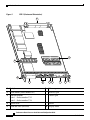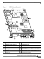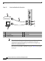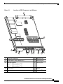
1
Performance Route Processor
Installation and Configuration Guide
Product Number: PRP-1=, PRP-1/R=, PRP-2=, PRP-2/R=
This hardware installation and configuration note describes the Performance
Route Processor (PRP) and the PRP-2, route processors for use in Cisco 12000
Series Routers.
Document Contents
This publication includes the following sections:
•
Important Information, page 2
•
Product Overview, page 5
•
Preparing for Installation, page 18
•
Removing and Installing a PRP, page 20
•
Checking the Installation, page 26
•
Upgrading to the PRP, page 32
•
Configuring Interfaces on the PRP, page 44
•
Additional Configuration and Maintenance Tasks, page 54
Corporate Headquarters:
Cisco Systems, Inc., 170 West Tasman Drive, San Jose, CA 95134-1706 USA
© 2008 Cisco Systems, Inc. All rights reserved.
Important Information
•
Regulatory, Compliance, and Safety Information, page 79
•
Obtaining Documentation, page 84
•
Documentation Feedback, page 85
•
Cisco Product Security Overview, page 85
•
Product Alerts and Field Notices, page 87
•
Obtaining Technical Assistance, page 88
•
Obtaining Additional Publications and Information, page 90
Important Information
This section contains information about the following hardware and software
requirements:
•
Router Information, page 2
•
Cisco IOS Software Requirements, page 3
•
Hardware Revision Requirements, page 4
•
Related Documentation, page 5
Router Information
For hardware installation and maintenance information on Cisco 12000 Series
Routers, refer to the installation and configuration guide for your router. This
includes information on card slot locations and other general requirements.
Supported Platforms
The PRP operates on all Cisco 12000 Series Routers and can be installed in any
available slot in any chassis. Cisco recommends that you install the PRP in the
section of the chassis that receives the least amount of airflow (if any). The PRP
runs cooler than other system cards and, therefore, does not require as much
airflow.
Performance Route Processor Installation and Configuration Guide
2
OL-11656-01
Important Information
PRP Redundancy
When two PRPs are installed in a Cisco 12000 Series Router, one PRP is the
active PRP and the other is a backup, or standby, PRP. If the active PRP fails or is
removed from the system, the standby PRP detects the failure and initiates a
switchover. During a switchover, the standby PRP assumes control of the router,
connects with the network interfaces, and activates the local network management
interface and system console.
Note
If your system includes redundant PRPs, both PRPs should be of the same type
(PRP-1 or PRP-2) and have the same memory size. Redundancy is not supported
when using a Gigabit Route Processor (GRP) and a PRP in the same chassis.
Cisco strongly recommends that you avoid configuring your router using mixed
route processor cards. Refer to the Route Processor Redundancy Plus for the
Cisco 12000 Series Internet Router publication for more information on
redundancy.
Cisco IOS Software Requirements
For software configuration information, refer to the Cisco IOS software
configuration and command reference publications for the installed Cisco IOS
Release. Also refer to the Cisco IOS software release notes for additional
information.
The PRP is compatible with Cisco IOS Release 12.0(22)S or later.
The show version and show hardware commands display the current hardware
configuration of the router, including the system software version that is currently
loaded and running. For complete descriptions of show commands, refer to the
Cisco IOS Configuration Fundamentals Configuration Guide and the Cisco IOS
Configuration Fundamentals Command Reference.
Performance Route Processor Installation and Configuration Guide
OL-11656-01
3
Important Information
Note
Output from the show version command on a PRP-2 card running on software
releases prior to 12.0(30)S may display some incorrect information. This is only
a display issue and it occurs because the software does not recognize some of the
hardware on the card. This does not affect the functionality of the PRP-2. For
example, the following is incorrect output from the show version command on
release 12.0(22)S:
cisco 12406/PRP (MPC7450) processor (revision 0x00) with 1048576K
bytes of memory. unknown CPU at 598Mhz, Rev 1.1, 256KB L2, 2048KB L3
Cache
The output from a later software release would be as follows:
cisco 12406/PRP (MPC7457) processor (revision 0x00) with 1048576K
bytes of memory. MPC7457 CPU at 1263Mhz, Rev 1.1, 512KB L2, 2048KB L3
Cache
Hardware Revision Requirements
To ensure compatibility with the software, the PRP should have a specific
hardware revision level or greater. The hardware revision number is printed on a
label affixed to the component side of the card. The hardware revision number can
also be displayed using the show diags slot-number command.
The minimum hardware revision number for the PRP (Product Number PRP-1=)
is 73-5936-05, Rev. A0. The minimum hardware revision number for the PRP-2
(Product Number PRP-2=) is 73-8812-04 Rev. A0.
Note
Output from the show diags command on a PRP-2 card running on software
releases prior to 12.0(30)S may incorrectly indicate “PRP-1+” or “FRU number
not known” as the installed FRU.
Performance Route Processor Installation and Configuration Guide
4
OL-11656-01
Product Overview
Related Documentation
For additional information on the PRP, refer to these publications:
•
Performance Route Processor Software Configuration in Cisco 12000 Series
Internet Routers
•
Route Processor Redundancy Plus for the Cisco 12000 Series Internet Router
•
Cisco IOS Release 12.0S Release Notes for Cisco 12000 Series Internet
Router
•
Cisco IOS Configuration Fundamentals Configuration Guide
•
Cisco IOS Configuration Fundamentals Command Reference
See the “Obtaining Documentation” section on page 84 for information on how to
obtain these publications.
Product Overview
The following sections provide information about the Performance Route
Processor (PRP), its components, functions, and features, and its use as the main
system processor for Cisco 12000 Series Routers. Figure 1 shows the front panel
view of the PRP-1.
PRP-1, Front Panel View
ETH 1
AUX
TX
75041
K
EN
TX
EN
K
LIN
PRIMARY
T
SE
RE
PRIMARY
CONSOLE
RX
RX
S
OT LOT
-0 -1
SL
EJ
EC
T
ETH 0
LIN
Figure 1
PERFORMANCE ROUTE PROCESSOR 1 (PRP-1)
The PRP-1 is available as Product Number PRP-1 or PRP-1=, which includes one
PRP with 512 MB of synchronous dynamic random-access memory (SDRAM)
and one 64-MB advanced technology attachment (ATA) Flash disk. A redundant
PRP (Product Number PRP-1/R) is also available.
Performance Route Processor Installation and Configuration Guide
OL-11656-01
5
Product Overview
Figure 2 shows the front panel view of the PRP-2.
ETH 1
BITS 0
BITS 1
AUX
CONSOLE
ETH 2
T
SE
RE
ETH 0
PERFORMANCE ROUTE PROCESSOR 2
101104
AC
T
SIG
AC
T
SIG
K
DA
TA
LIN
LIN
SL
S
OT LOT
-0 -1
K
PRP-2, Front Panel View
DA
TA
Figure 2
The PRP-2 is available as Product Number PRP-2 or PRP-2=, which includes one
PRP with 1 G of synchronous dynamic random-access memory (SDRAM) and
one 64-MB advanced technology attachment (ATA) Flash disk. A redundant PRP
(Product Number PRP-2/R) is also available.
PRP Functions
The PRP-1 for the Cisco 12000 Series Router includes the following primary
functions:
•
Loading Cisco IOS software on all installed line cards at power up
•
Providing a console (terminal) port for router configuration
•
Providing an auxiliary port for other external equipment (such as modems)
•
Providing two IEEE 802.3, 10/100-megabits-per-second (Mbps) Ethernet
ports for Telnet functionality
•
Running routing protocols
•
Building and distributing routing tables to line cards
•
Providing general system maintenance functions
•
Communicating with line cards either through the switch fabric or through
the maintenance bus (MBus). The MBus connection allows the PRP to
download a system bootstrap image, collect or load diagnostic information,
and perform general, internal system maintenance operations. The switch
fabric connection is the main data path for routing table distribution as well
as for packets that are sent between line cards and the PRP.
Performance Route Processor Installation and Configuration Guide
6
OL-11656-01
Product Overview
In addition to the functionality listed for the PRP-1, the PRP-2 provides the
following additional functions:
•
One IEEE 802.3 10/100/1000-megabits-per-second (Mbps) Ethernet port
•
Two building integrated timing system (BITS) ports for connecting to an
external clock source
PRP Components
The PRP-1 contains the following components:
•
PowerPC processor—Motorola PowerPC 7450 central processing unit
(CPU). The CPU runs at an external bus clock speed of 133 MHz and an
internal clock speed of 667 MHz.
•
SDRAM—Up to 2 gigabytes (GB) of Cisco-approved synchronous dynamic
random-access memory (SDRAM) on two dual in-line memory modules
(DIMMs). 512 MB of SDRAM is the default shipping configuration.
SDRAM is field replaceable only when using Cisco-approved DIMMs.
•
SRAM—2 megabytes (MB) of static random-access memory (SRAM) for
secondary CPU cache memory functions. SRAM is not user configurable or
field replaceable.
•
NVRAM—2 MB of nonvolatile RAM (NVRAM). NVRAM is not user
configurable or field replaceable.
•
Memory—Additional memory components include onboard Flash memory
and up to two Flash disks.
•
Sensors—Air-temperature sensors for environmental monitoring.
Performance Route Processor Installation and Configuration Guide
OL-11656-01
7
Product Overview
The PRP-2 contains the following additional components:
•
Note
SDRAM—Up to 4 GB of Cisco-approved synchronous dynamic
random-access memory (SDRAM) on two dual in-line memory modules
(DIMMs). 1 GB of SDRAM is the default shipping configuration. SDRAM is
field replaceable only when using Cisco-approved DIMMs.
Software releases prior to 12.0(30)S do not recognize more than 2 GB of
SDRAM and will only use the first 2 GB of the installed memory. This
does not affect the functioning of the PRP-2, but commands such as show
version will indicate that only 2 GB of SDRAM are installed.
•
Hard disk drive—40-GB hard disk drive can be optionally installed on the
PRP-2 board.
•
CF—1-GB compact flash disk can be optionally installed on the PRP-2
board.
Cisco IOS Software Storage
The Cisco IOS software images that run the Cisco 12000 Series Router system are
stored in Flash memory. Two types of Flash memory ship with the PRP-1:
•
Onboard Flash memory—Ships as a single in-line memory module (SIMM).
This Flash memory contains the Cisco IOS boot image (bootflash) and is not
field replaceable.
•
Flash disk—The PRP ships with an ATA Flash disk that can be installed in
either Flash disk slot. The Flash disk contains the Cisco IOS software image.
Linear Flash memory cards are also supported in the PRP-1.
Performance Route Processor Installation and Configuration Guide
8
OL-11656-01
Product Overview
The PRP-2 provides the following additional Flash memory:
•
Compact Flash (CF) disk—Optional 1 GB CF can be used for large IOS
images.
Storing the Cisco IOS images in Flash memory enables you to download and boot
from upgraded Cisco IOS software images remotely, or from software images that
reside in PRP Flash memory.
Cisco 12000 Series Routers support downloadable system software for most
Cisco IOS software upgrades. This enables you to remotely download, store, and
boot from a new Cisco IOS software image. The Cisco IOS software runs from
within the SDRAM of the PRP.
For specific Cisco IOS software requirements for the PRP, see the “Cisco IOS
Software Requirements” section on page 3.
PRP Hardware Components
Figure 3 shows the locations of the various hardware components on the PRP-1.
Figure 4 shows the locations of the various hardware components on the PRP-2.
Memory options and functions for both are listed in Table 1.
Performance Route Processor Installation and Configuration Guide
OL-11656-01
9
Product Overview
Figure 3
PRP-1 (Horizontal Orientation)
1
3
2
ETH 0
-1
OT
SL
-0
OT
SL
T
PRIMARY
CONSOLE
TX
K
LIN
SE
5
AUX
RX
EN
RE
PRIMARY
4
ETH 1
RX
TX
EN
K
LIN
PERFORMANCE ROUTE PROCESSOR 1 (PRP-1)
7 8
6
1
Backplane connector
6
Ethernet ports
2
Flash SIMM (Socket number P3)
7
Auxiliary port
3
SDRAM DIMMs
Bank 1 - Socket number U15
Bank 2 - Socket number U18
8
Console port
4
Ejector lever
9
Handle
5
Flash disk slots (covered)
10 Display LEDs
9
10
75042
T
EC
EJ
Performance Route Processor Installation and Configuration Guide
10
OL-11656-01
Product Overview
PRP-2 (Horizontal Orientation)
FA CE
PL AT
E
800
-24
060
HD -P
-01
RP 2-
REV
__
40 G
Figure 4
TH IS
SI DE
TO
14
1
2
13
12
K
LIN
ETH 0
3
TA
DA
K
LIN
ETH 1
5
TA
DA
SIG
BITS 0
T
AC
SIG
BITS 1
6
T
AC
AUX
CONSOLE
7
8
ETH 2
T
SE
RE
-1
OT
SL
-0
OT
SL
PERFORMANCE ROUTE PROCESSOR 2
9
10 11
101105
T
EC
EJ
4
1
Compact Flash disk (optional)
8
Console port
2
Flash SIMM (Socket number P3)
9
Gigabit Ethernet port
3
Ejector lever
10 Handle
4
Flash disk slots (covered)
11 Display LEDs
5
Ethernet ports
12 SDRAM DIMM: Bank 1 - Socket number U15
6
BITS ports
13 SDRAM DIMM: Bank 2 - Socket number U18
7
Auxiliary port
14 Hard disk drive (optional)
Performance Route Processor Installation and Configuration Guide
OL-11656-01
11
Product Overview
Table 1
PRP Memory Components
Type
SDRAM
Size
1
Quantity
Description
Location
512 MB or 1 GB 1 or 2
512-MB and 1-GB DIMMs (based on
U15 (bank
desired SDRAM configuration) for main 1)2
Cisco IOS software functions
U18 (bank 2)
2 MB (fixed)
—
Secondary CPU cache memory functions —
2 MB (fixed)
1
System configuration files, register
settings, and logs
1
Contains Cisco IOS boot image
P3
(bootflash), crash information, and other
user-defined files
Flash disks6
1 or 2
Contains Cisco IOS software images,
system configuration files, and other
user-defined files on up to two Flash
disks
Flash disk
slot 0 and
slot 1
1 GB CF7
1
Contains large Cisco IOS images
—
Flash boot
ROM
512 KB
1
Flash EPROM for the ROM monitor
program boot image
—
HDD8
40 GB
1
Contains log and crash information for
specific Cisco IOS versions
—
SRAM3
NVRAM
4
Flash memory 64 MB SIMM5
—
1. Default SDRAM configuration is 512 MB for PRP-1 and 1-GB for PRP-2. Bank 1 (U15) must be populated first. You can
use one or both banks to configure SDRAM combinations of 512 MB, 1 GB, or 2 GB for the PRP-1 and 1 GB, 2 GB, 3 GB,
and 4 GB for the PRP-2. 1.5-GB configurations.and non-Cisco DIMM devices are not supported.
2. If both banks of the PRP-1 are populated, bank 1 and bank 2 must contain the same size DIMM.
3. SRAM is not user configurable or field replaceable.
4. NVRAM is not user configurable or field replaceable.
5. Flash memory SIMM is not user configurable or field replaceable.
6. ATA Flash disks are supported in the PRP-2; both ATA Flash disks and linear Flash memory cards are supported in the
PRP-1.
7. Optional PRP-2 hardware. Non-Cisco compact disks are not supported.
8. Optional PRP-2 hardware. Non-Cisco hard disk drives are not supported.
Note
If a single DIMM module is installed, it must be placed in bank 1 (U15).
Performance Route Processor Installation and Configuration Guide
12
OL-11656-01
Product Overview
SDRAM
SDRAM stores routing tables, protocols, and network accounting applications,
and runs the Cisco IOS software. The default PRP-1 configuration includes 512
MB of error checking and correction (ECC) SDRAM. DIMM upgrades of 512 MB
and 1 GB are available for the PRP-1. You cannot mix memory sizes. If two
DIMMS are installed, they must be the same memory size.
The default PRP-2 configuration includes 1 GB of ECC SDRAM. DIMM
upgrades of 1 GB and 2 GB are available for the PRP-2. You can mix memory
sizes as long as the larger DIMM is placed in bank 1 (U15).
Caution
Only Cisco-approved memory is supported. Do not attempt to install other devices
or non-Cisco approved DIMMs in the DIMM sockets. (See Table 15 on page 74.)
SRAM
SRAM provides 2 MB of parity-protected, secondary CPU cache memory. Its
principal function is to be a staging area for routing table updates and for
information sent to and from line cards. SRAM is not user configurable or field
replaceable.
NVRAM
NVRAM provides 2 MB of memory for system configuration files, software
configuration register settings, and environmental monitoring logs. This
information is backed up with built-in lithium batteries that retain the contents for
a minimum of 5 years. NVRAM is not user configurable or field replaceable.
Performance Route Processor Installation and Configuration Guide
OL-11656-01
13
Product Overview
Flash Memory
Flash memory allows you to remotely load and store multiple Cisco IOS software
and microcode images. You can download a new image over the network or from
a local server and then add the new image to Flash memory or replace the existing
files. You then can boot the routers either manually or automatically from any of
the stored images.
Flash memory also functions as a Trivial File Transfer Protocol (TFTP) server to
allow other servers to boot remotely from stored images or to copy them into their
own Flash memory. The onboard Flash memory (called bootflash) contains the
Cisco IOS boot image, and the Flash disk contains the Cisco IOS software image.
PRP LEDs
The following LEDs are used on the PRP:
•
Status LEDs
•
Display LEDs
Status LEDs
The PRP-1 has the following Status LED indicators:
•
Two Flash disk activity LEDs, one for each Flash disk slot (labeled SLOT-0
and SLOT-1)—Indicate when the Flash disk slot is accessed.
•
Four Ethernet port LEDs used in conjunction with each of the RJ-45 Ethernet
connectors:
– LINK—link activity
– EN—port enabled
– TX—data transmission
– RX data reception
•
Two Ethernet connection LEDs, one for each Ethernet port (labeled
PRIMARY)—Identify which of the two Ethernet connections is selected.
Performance Route Processor Installation and Configuration Guide
14
OL-11656-01
Product Overview
The PRP-2 has the following LED indicators:
•
Two Flash disk activity LEDs, one for each Flash disk slot (labeled SLOT-0
and SLOT-1)—Indicate when the Flash disk slot is accessed.
•
Two Ethernet port LEDs used in conjunction with each of the three RJ-45
Ethernet connectors:
– LINK—indicates link activity
– DATA—indicates data transmission or reception
•
Two BITS port LEDs used in conjunction with each of the two BITS ports:
– SIG—indicates carrier signal available
– ACT—indicates the interface is active
Display LEDs
The alphanumeric display LEDs are organized as two rows of four characters each
and are located at one end of the card. These LEDs provide system status and error
messages that are displayed during and after the boot process. The boot process
and the content displayed are controlled by the MBus module software of the PRP.
At the end of the boot process, the LEDs are controlled by the Cisco IOS software
(via the MBus), and the content displayed is designated by the Cisco IOS
software.
A complete, descriptive list of all system and error messages is located in the
Cisco IOS System Error Messages publications.
The display LEDs indicate the following:
•
Status of the PRP
•
System error messages
•
User-defined status/error messages
Performance Route Processor Installation and Configuration Guide
OL-11656-01
15
Product Overview
Soft Reset Switch
A soft reset switch provides a reset to the processor software on the PRP. You
access the soft reset switch through a small opening in the PRP faceplate. To
depress the switch, insert a paper clip or a similar object into the opening.
Caution
The soft reset switch is not a mechanism for resetting the PRP and reloading the
IOS image. It is intended for software development use. To prevent system
problems or loss of data, use the soft reset switch only on the advice of Cisco
service personnel.
Flash Disk Slots
The PRP includes two Flash disk slots on the front panel of the card. Either slot
on the PRP-1 can support an ATA Flash disk or a linear Flash memory card. The
Flash disk slots on the PRP-2 can only support ATA Flash disks.
Note
The PRP only supports +5 VDC Flash disk devices. It does not support +3.3 VDC
Flash disk devices.
All combinations of different Flash devices are supported by the PRP-1. You can
use ATA Flash disks, linear Flash memory cards, or a combination of the two.
Each Flash disk slot has an ejector button for ejecting a card from the slot. See the
“Using Flash Disks in the PRP” section on page 61 for more information.
Note
Linear Flash memory cards may not have the capacity to meet the requirements
of your configuration. However, they can be used for emergency file recovery
applications.
Performance Route Processor Installation and Configuration Guide
16
OL-11656-01
Product Overview
Asynchronous Serial Ports
The PRP has two asynchronous serial ports, the console and auxiliary ports. These
allow you to connect external serial devices to monitor and manage the system.
Both ports use RJ-45 receptacles.
The console port provides a data circuit-terminating equipment (DCE) interface
for connecting a console terminal. The auxiliary port provides a data terminal
equipment (DTE) interface and supports flow control. It is often used to connect
a modem, a channel service unit (CSU), or other optional equipment for Telnet
management.
Ethernet Ports
The PRP includes two 10/100 Mbps Ethernet ports, each using an 8-pin RJ-45
receptacle for either IEEE 802.3 10BASE-T (10 Mbps) or IEEE 802.3u
100BASE-TX (100 Mbps) connections.
The PRP-2 includes a 10/100/1000 Mbps Ethernet port, which uses the above
connections and also a 802.3 Gigabit Ethernet connection.
Note
The transmission speed of the Ethernet ports is auto-sensing by default and is user
configurable.
Hard Disk Drive
The PRP-2 optionally includes a 40-GB hard disk drive (HDD) that is installed on
the PRP-2 board.
Note
Non-Cisco hard disk drives are not supported.
Performance Route Processor Installation and Configuration Guide
OL-11656-01
17
Preparing for Installation
Compact Flash Disk
The PRP-2 optionally includes a 1-GB compact flash disk that is installed on the
PRP-2 board.
Note
Non-Cisco compact flash disks are not supported.
Preparing for Installation
Installation preparation is presented in the following sections:
•
Safety Guidelines, page 18
•
Preventing Electrostatic Discharge, page 19
•
Required Tools and Equipment, page 20
•
Working with Electrical Equipment, page 20
Safety Guidelines
Before you perform any procedure in this publication, review the safety
guidelines in this section to avoid injuring yourself or damaging the equipment.
The following guidelines are for your safety and to protect equipment. The
guidelines do not include all hazards. Be alert.
Note
Review the safety warnings listed in the Regulatory Compliance and Safety
Information for Cisco 12000 Series Internet Router publication (Document
Number 78-4347-xx) that accompanied your router before installing, configuring,
or maintaining a line card.
•
Keep the work area clear and dust free during and after installation. Do not
allow dirt or debris to enter into any laser-based components.
•
Do not wear loose clothing, jewelry, or other items that could get caught in
the router while working with line cards.
Performance Route Processor Installation and Configuration Guide
18
OL-11656-01
Preparing for Installation
•
Cisco equipment operates safely when it is used in accordance with its
specifications and product usage instructions.
•
If you plan to replace a PRP, back up your current configuration file to a
remote server or to Flash memory before you remove the PRP. This prevents
you from having to reenter all your current configuration information
manually. To back up the file, copy your configuration file to a Flash disk or
access a remote server.
Preventing Electrostatic Discharge
Electrostatic discharge (ESD) damage, which can occur when electronic cards or
components are improperly handled, results in complete or intermittent failures.
Electromagnetic interference (EMI) shielding is an integral component of the line
card. Cisco recommends using an ESD-preventive strap whenever you are
handling network equipment or one of its components.
The following are guidelines for preventing ESD damage:
Warning
•
Always use an ESD-preventive wrist or ankle strap and ensure that it makes
good skin contact. Connect the equipment end of the connection cord to an
ESD connection socket on the router or to bare metal on the chassis.
•
Handle PRPs by the captive installation screws, the provided handle, ejector
levers, or the line card metal carrier only; avoid touching the board or
connector pins.
•
Place removed PRPs board-side-up on an antistatic surface or in a static
shielding bag. If you plan to return the component to the factory, immediately
place it in a static shielding bag.
•
Avoid contact between the PRPs and clothing. The wrist strap only protects
the board from ESD voltages on the body; ESD voltages on clothing can still
cause damage.
For safety, periodically check the resistance value of the ESD strap. The
measurement should be between 1 and 10 megohms.
Performance Route Processor Installation and Configuration Guide
OL-11656-01
19
Removing and Installing a PRP
Required Tools and Equipment
You need the following tools and parts to remove and install a PRP:
•
Flat-blade or Phillips screwdriver
•
ESD-preventive wrist strap and instructions
•
Antistatic mat, foam pad, or bag for the removed PRP. Place the removed PRP
into an antistatic bag if you plan to return it to the factory, or on an antistatic
mat or foam if you are replacing components and will reinstall the PRP.
Working with Electrical Equipment
Follow these basic guidelines when working with any electrical equipment:
•
Before beginning any procedure requiring access to the chassis interior,
locate the emergency power-off switch for the room in which you are
working.
•
Disconnect all power and external cables before moving a chassis.
•
Do not work alone when potentially hazardous conditions exist; never assume
that power has been disconnected from a circuit; always check.
•
Do not perform any action that creates a potential hazard to people or makes
the equipment unsafe.
•
Carefully examine your work area for possible hazards such as moist floors,
ungrounded power extension cables, and missing safety grounds.
Removing and Installing a PRP
The following sections describe the procedures for removing and installing a PRP
as well as removing and installing other field-replaceable hardware on the PRP-2
board. Before beginning the procedures, verify that your system meets the
minimum requirements as described in the “Preparing for Installation” section on
page 18.
•
Removing a PRP, page 21
•
Installing a PRP, page 24
Performance Route Processor Installation and Configuration Guide
20
OL-11656-01
Removing and Installing a PRP
Note
The procedures in the following sections use illustrations of a Cisco 12404
Internet Router to support the descriptions of installing and removing a route
processor card. The card cages of Cisco 12000 Series Routers differ in many
ways. However, the process of installing and removing a route processor card are
basically the same across the entire chassis line. Therefore, separate procedures
and illustrations for each chassis are not included in this publication.
Caution
Cisco recommends that you do not remove a PRP while the system is operating.
Doing so will cause the system to stop forwarding packets and might cause the
system to cease network operation. If you are upgrading your router from a GRP
to a PRP, you must first power down the router and then switch out the RP cards.
Cisco strongly recommends that you avoid configuring your router using mixed
RP cards. If RP redundancy is desired, you must install two PRPs.
Note
You must remove the PRP-2 before you can install or remove the compact flash
disk or the hard disk drive. See the “Additional Configuration and Maintenance
Tasks” section on page 54 for more information.
Removing a PRP
When you remove a PRP from a slot, be sure to use the ejector levers, which help
to ensure that the PRP is fully dislodged from the backplane connector. A PRP
that is only partially removed from the backplane can halt the system. (See
Figure 6.)
Caution
Before you replace the PRP, back up the running configuration to a TFTP server
or a Flash disk so that you can retrieve it later. If the configuration is not saved, it
will be lost and you will have to reenter the entire configuration manually. This
procedure is not necessary if you are temporarily removing a PRP; lithium
batteries will retain the configuration in memory until you replace the PRP in the
system.
Performance Route Processor Installation and Configuration Guide
OL-11656-01
21
Removing and Installing a PRP
Figure 5 illustrates the PRP installed in a chassis.
Figure 5
CONNECTOR
CLASS 1 LASER
LASERPRODUKT PRODUCT
PRODUIT LASER DER KLASSE 1
DE CLASSE
1
PRODUCTO LASER
DE CLASSE 1
TX
0
1
RX
2
3
T
EC
EJ
ACTIVE
CARRIER
-1
OT
SL
-0
OT
SL
ETH 0
RX PKT
ETH 1
AUX
RX
EN
PRIMARY
RX
TX
K
LIN
EN
PRIMARY
CONSOLE
75040
CLEAN
WITH ALCOHOL
WIPES
BEFORE
CONNECTING
Installed PRP (Cisco 12404 Shown)
40C48/POS
-SR-SC
TX
K
LIN
RE
SE
T
CR
IT
IC MA MI
AL JO NO
R
R
PERFORMAN
CE ROUTE
PROCESSOR
1
(PRP-1)
MBUS
ALARM
FAIL
FABRIC
ENABLE
CONSOLI
2
1
1
PRP
DATED
SWITCH
FABRIC
2
2
Ejector Levers
Performance Route Processor Installation and Configuration Guide
22
OL-11656-01
Removing and Installing a PRP
Figure 6 shows the ejector levers in detail.
Figure 6
Ejector Lever Detail (Cisco 12404 shown)
a
CLASS 1 LASER
LASERPROD PRODUCT
UKT DER KLASSE
PRODUIT LASER
DE CLASSE 1
1
PRODUCTO LASER
DE CLASSE 1
CLEAN
CONNECTOR
WITH ALCOHOL
WIPES
BEFORE
CONNECTING
b
TX
0
1
RX
2
3
ACTIVE
CARRIER
RX PKT
T
SL
SL
-1
OT
-0
OT
ETH 0
40C48/POS-
ETH 1
AUX
RX
EN
PRIMARY
LIN
RX
TX
K
EN
PRIMARY
LIN
75039
EJ
EC
SR-SC
CONSOLE
TX
K
RE
CR
ITI MA
CA JO MI
NO
L
R
R
SE
T
PERFORMANC
E ROUTE
MBUS
PROCESSOR
1
ALARM
(PRP-1)
FAIL
FABRIC
ENABLE
CONSOLI
DATED
SWITCH
FABRIC
To remove a PRP, follow these steps:
Step 1
If you are replacing the PRP in a system with only one PRP, copy the currently
running configuration file to a TFTP server or to a Flash disk so that you can
retrieve it later.
Step 2
Turn off system power.
Step 3
Attach an ESD-preventive wrist strap and follow its instructions for use.
Step 4
If you are replacing a PRP, disconnect any devices that are attached to the
Ethernet, console, or auxiliary ports. If you are removing a PRP for maintenance
and will reinstall the same one, you can leave the devices attached, provided that
doing so will not strain the cables.
Step 5
Using a 3/16-inch flat-blade screwdriver, loosen the two captive screws on the
ends of the PRP.
Performance Route Processor Installation and Configuration Guide
OL-11656-01
23
Removing and Installing a PRP
Step 6
Place your thumbs on the ends of each of the ejector levers and simultaneously
pull them both away from the PRP faceplate (in the direction shown in Figure 6a)
to release the PRP from the upper card cage slot and to dislodge the PRP edge
connector from the backplane.
Step 7
Grasp the PRP faceplate handle with one hand and pull the PRP straight out of the
slot, keeping your other hand under the PRP to guide it. Keep the PRP edge
connector parallel to the backplane.
Caution
Avoid touching the PRP printed circuit board, components, or any edge connector
pins.
Step 8
Place the removed PRP on an antistatic mat or foam. If you plan to return the PRP
to the factory, immediately place it in an antistatic bag to prevent ESD damage.
Installing a PRP
When you install a PRP, be sure to use the ejector levers, which help to ensure that
the PRP is fully inserted in the backplane connector. (See Figure 6.) When you
push the ejector levers simultaneously inward (toward the center of the PRP), the
ejector levers push the PRP into the slot and ensure that the PRP backplane
connector is fully seated in the backplane.
Caution
A PRP that is only partially connected to the backplane can halt the system.
To install a PRP, follow these steps:
Step 1
Turn off system power.
Step 2
Attach an ESD-preventive wrist strap and follow its instructions for use.
Step 3
Grasp the PRP faceplate handle with one hand and place your other hand under
the carrier to support and guide it into an upper card cage slot.
Performance Route Processor Installation and Configuration Guide
24
OL-11656-01
Removing and Installing a PRP
Caution
Avoid touching the PRP printed circuit board, components, or any edge connector
pins.
Step 4
Place the bus-connector edge of the PRP in the appropriate slot and align the
notches along the edge of the carrier with the grooves at the top and bottom of the
slot.
Step 5
While keeping the PRP edge connector parallel to the backplane, carefully slide
the carrier into the slot until the PRP faceplate makes contact with the ejector
levers, then stop.
Step 6
Using the thumb and forefinger of each hand to pinch each ejector lever, push both
ejectors simultaneously toward the center of the PRP faceplate until they are
perpendicular to the PRP faceplate. (See Figure 6b.)
Step 7
Using a 3/16-inch flat-blade screwdriver, tighten the captive screws on the ends
of the PRP. The captive screws prevent the PRP from becoming partially
dislodged from the backplane and ensure proper EMI shielding. (These captive
screws must be tightened to meet EMI specifications.)
Step 8
If you disconnected cables to remove the PRP, or if you are installing a new PRP,
reconnect the cables to the appropriate ports. (See the “Checking the Installation”
section on page 26.)
Step 9
Ensure that the console terminal is turned on.
Step 10
Turn on system power.
Step 11
Attach the network end of your RJ-45 cable to your transceiver, switch, hub,
repeater, DTE, or other external equipment. Be sure to use the appropriate strain
relief on cable connections.
Performance Route Processor Installation and Configuration Guide
OL-11656-01
25
Checking the Installation
Checking the Installation
This section assists you in confirming that the PRP is installed successfully and
includes the following sections:
•
PRP Boot Process, page 26
•
Starting the System and Observing Initial Conditions, page 27
•
Verifying Interface Status, page 31
PRP Boot Process
The following sequence describes a typical PRP boot process:
1.
System power is turned on.
2.
MBus module receives +5 VDC and starts executing MBus software.
3.
PRP determines the system configuration by sending a message over the
MBus requesting all installed devices to identify themselves. The return
response provides slot number, and card and component type. The PRP, line
cards, and clock scheduler cards (CSCs) are then powered up.
4.
PRP power-on-reset logic delay, which allows power and both local and CSC
clocks to stabilize.
5.
After the power-on reset is released, the PRP begins to execute the ROM
monitor software.
6.
If the ROM monitor is configured to autoboot, it loads and boots the Cisco
IOS software.
or
If the ROM monitor is not configured to autoboot, you must enter the
appropriate b command at the ROM monitor prompt (Rommon>) to boot the
Cisco IOS software.
7.
When the Cisco IOS software boots, it polls all other cards in the system and
powers them up, loading their Cisco IOS software as needed.
Performance Route Processor Installation and Configuration Guide
26
OL-11656-01
Checking the Installation
Starting the System and Observing Initial Conditions
This section describes the initial system startup processes and procedures.
To start your system, follow these steps:
Step 1
Turn on each installed power supply by turning its system power switch to the on
(|) position.
For AC-input power supplies, the green AC OK LED should go on. For DC-input
power supplies, the green input OK LED should go on. For both types of power
supplies, the output fail LED should be off.
Step 2
Listen for the system blower modules or fan trays in the router; you should
immediately hear them operating. In a noisy environment, place your hand in
front of the exhaust vents to verify that the blower modules are operating.
Step 3
During the PRP boot process, observe the PRP alphanumeric display LEDs,
which are located at one end of the PRP, near the ejector lever. (See Figure 7.)
The 4-digit displays show system messages and displays a sequence similar to that
shown in Table 2.
Performance Route Processor Installation and Configuration Guide
OL-11656-01
27
Checking the Installation
Figure 7
PRP Alphanumeric Display LEDs (Vertical View)
PROCESSOR 1 (PRP-1)
1
70694
2
1
Upper (or left if horizontal) LED Display
Table 2
2
Lower (or right if horizontal) LED Display
PRP Alphanumeric Display LED Sequences
LED Display
Description
MROM
nnnn
PRP microcode loads into MBus random-access memory (RAM); where nnnn
is the microcode version. For example, Microcode Version 1.17 displays as
0117.1
RP
RDY
The ROMMON for this PRP is enabled and recognized by the system.
ACTV
RP
Cisco IOS is enabled and this PRP is the active PRP.
STBY
RP
Cisco IOS is enabled and this PRP is in standby mode.
1. The version of microcode running on your PRP might be different.
Performance Route Processor Installation and Configuration Guide
28
OL-11656-01
Checking the Installation
Step 4
During the line card boot process, which occurs immediately after the PRP boots,
observe the alphanumeric display LEDs on each line card.
The system attempts to boot identical line cards in parallel. Furthermore, the
system boots line cards as soon as they are powered on and become available for
a system boot. The physical location of the alphanumeric display LEDs on the line
cards is the same as on the PRP, which is shown in Figure 7.
See the appropriate line card installation and configuration note for complete
details on line card display LED sequences.
You must meet the following criteria to successfully boot the PRP:
•
Flash disk is installed in Flash disk slot 0
•
Flash disk contains a valid Cisco IOS software image
•
Software configuration register is set to 0x2102
The system automatically boots this Cisco IOS software image. The system then
enters the setup facility, where you are prompted to perform a basic configuration
of the system.
Otherwise, the system enters the ROM monitor and the appropriate prompt
appears (Rommon>).
Step 5
Caution
If the ROM monitor prompt (Rommon>) appears, you must boot the Cisco IOS
software image you want to use by entering the appropriate b command at the
ROM monitor prompt:
•
b—Boots the default system software from onboard Flash memory
(if it is present in onboard Flash memory)
•
b filename [host]—Boots the file filename from the server host using TFTP
•
b flash—Boots the first file in the Flash memory card in Flash card slot 0
To prevent system problems, use the b flash command option carefully;
otherwise, you might instruct the system to boot a non-Cisco IOS software image
from Flash memory. This command is not used with Flash disks.
•
b slot0: filename—Boots the file filename from the Flash memory card in
Flash card slot 0
•
b slot1: filename—Boots the file filename from the Flash memory card in
Flash card slot 1
Performance Route Processor Installation and Configuration Guide
OL-11656-01
29
Checking the Installation
Caution
•
b flash disk0: filename—Boots the file filename from the Flash disk in Flash
card slot 0
•
b flash disk1: filename—Boots the file filename from the Flash disk in Flash
card slot 1
The b flash disk0: and b flash disk1: commands are only used from the ROM
monitor (Rommon>) prompt if the system fails to load normally. Do not use these
commands from the router (Router>) prompt.
While the system boots, the console screen displays a script and system banner
similar to the following:
Cisco Internetwork Operating System Software
IOS (tm) GS Software (PRP-P-MZ), Released Version 12.0(22)S
Copyright (c) 1986-2002 by cisco Systems, Inc.
Compiled Sat 10-May-02 06:02a
Step 6
Observe the system startup banner. When you start up an unconfigured system for
the first time, the system automatically enters the setup facility, which determines
which interfaces are installed and prompts you for configuration information for
each one.
On the console screen, after the system displays the system banner and hardware
configuration, the following System Configuration Dialog prompt appears:
--- System Configuration Dialog --At any point you may enter a question mark '?' for help.
Use ctrl-c to abort configuration dialog at any prompt.
Default settings are in square brackets '[]'.
Continue with configuration dialog? [yes/no]:
Step 7
You can either proceed with the setup facility or exit from setup and use
configuration commands to configure global (system-wide) and interface-specific
parameters.
You do not have to configure the interfaces immediately; however, you cannot
enable the interfaces or connect them to any networks until they are configured.
Performance Route Processor Installation and Configuration Guide
30
OL-11656-01
Checking the Installation
The interface-specific LEDs on line cards might not go on until after you
configure the line card interfaces. To verify correct operation of each interface,
complete the first-time setup procedures and configuration, then refer to the LED
descriptions in the configuration notes for each line card to check the status of the
interfaces.
Verifying Interface Status
The status LEDs on the PRP indicate system and PRP status, which Flash disk slot
is active, which Ethernet connection is in use, and what is occurring on the
Ethernet interface. This section provides functional descriptions of the status
LEDs on the PRP-1 and PRP-2 (see Figure 8 and Figure 9) and the processes you
should observe.
PRP-1 LEDs (Partial Front Panel View)
ETH 1
TX
RX
K
EN
TX
PRIMARY
70693
PRIMARY
LIN
K
EN
SL
RX
S
OT LOT
-0 -1
ETH 0
LIN
Figure 8
The PRP-1 has the following LED indicators:
•
Two Flash disk activity LEDs, one for each Flash disk slot (labeled SLOT-0
and SLOT-1)—Identify which of the two Flash disk slots is accessed.
•
Four Ethernet port LEDs used in conjunction with each of the RJ-45 Ethernet
connectors:
– LINK—link activity
– EN—port enabled
– TX—data transmission
– RX—data reception
•
Two Ethernet connection LEDs, one for each Ethernet port (labeled
PRIMARY)—Identify which of the two Ethernet connections is selected.
Performance Route Processor Installation and Configuration Guide
OL-11656-01
31
Upgrading to the PRP
AC
T
SI
G
AC
T
SI
G
DA
TA
K
LIN
LIN
S
OT LOT
- 0 -1
ETH 0
ETH 1
BITS 0
BITS 1
ETH 2
101108
SL
DA
TA
PRP-2 LEDs (Partial Front Panel View)
K
Figure 9
The PRP-2 has the following LED indicators:
•
Two Flash disk activity LEDs, one for each Flash disk slot (labeled SLOT-0
and SLOT-1)—Identify which of the Flash disk slots is accessed.
•
Two Ethernet port LEDs used in conjunction with each of the three RJ-45
Ethernet connectors:
– LINK—indicates link activity
– DATA—indicates data transmission or reception
•
Two BITS port LEDs used in conjunction with each of the two BITS ports:
– SIG—indicates carrier signal available
– ACT—indicates the interface is active
Upgrading to the PRP
This section details how to upgrade from the GRP to the PRP. The procedures
described are the same whether you are upgrading to a PRP-1 or PRP-2.
•
Upgrading to the PRP Without Rebooting the Router, page 33
•
Upgrading to the PRP With Rebooting the Router, page 40
•
Differentiating Between PRP-1 and PRP-2, page 43
Performance Route Processor Installation and Configuration Guide
32
OL-11656-01
Upgrading to the PRP
Upgrading to the PRP Without Rebooting the Router
To upgrade to the PRP from the GRP without interruption of service, you must
have support for High Availability in your router. This means that two GRPs must
be installed in the router and the redundancy must be set to either SSO or RPR+
mode. To configure the redundancy, use the redundancy command in global
configuration mode. To view the redundancy configuration on the RPs, use the
show redundancy command.
To upgrade to the PRP using High Availability, use the following procedure:
Step 1
Verify that there are two GRPs in the router, both running the same Cisco IOS
version, and that the router is configured for SSO or RPR+ redundancy. The show
redundancy command indicates the redundancy mode as well as the Cisco IOS
version running on the GRPs. Take note of the Cisco IOS version running on the
GRPs (12.0(26)S in this example).
Router# show redundancy
Redundant System Information :
-----------------------------Available system uptime
Switchovers system experienced
Standby failures
Last switchover reason
=
=
=
=
1 day, 47 minutes
0
0
none
Hardware Mode
Configured Redundancy Mode
Operating Redundancy Mode
Maintenance Mode
Communications
=
=
=
=
=
Duplex
SSO
SSO
Disabled
Up
Current Processor Information :
------------------------------Active Location = slot 3
Current Software state = ACTIVE
Uptime in current state = 1 day, 47 minutes
Image Version = Cisco Internetwork Operating System
Software
IOS (tm) GS Software (GSR-P-M), Version 12.0(26)S, EARLY DEPLOYMENT
RELEASE SOFTWARE (fc1)
TAC Support: http://www.cisco.com/tac
Copyright (c) 1986-2003 by cisco Systems, Inc.
Compiled Mon 25-Aug-03 10:44 by nmasa
BOOT =
CONFIG_FILE =
Performance Route Processor Installation and Configuration Guide
OL-11656-01
33
Upgrading to the PRP
BOOTLDR =
Configuration register = 0x2102
Peer Processor Information :
---------------------------Standby Location = slot 4
Current Software state = STANDBY HOT
Uptime in current state = 2 hours, 13 minutes
Image Version = Cisco Internetwork Operating System
Software
IOS (tm) GS Software (GSR-P-M), Version 12.0(26)S, EARLY DEPLOYMENT
RELEASE SOFTWARE (fc1)
TAC Support: http://www.cisco.com/tac
Copyright (c) 1986-2003 by cisco Systems, Inc.
Compiled Mon 25-Aug-03 10:44 by nmasa
BOOT =
CONFIG_FILE =
BOOTLDR =
Configuration register = 0x2102
Step 2
Remove the Flash disk from the PRP card and install it into slot 1 of the active RP.
The following message will be displayed; do not format the disk.
22:21:31: %PCMCIAFS-5-DIBERR: PCMCIA disk 1 is formatted from a
different router or PC. A format in this router is required before an
image can be booted from this device
Note
Step 3
If your router is running an image prior to Cisco IOS Release 12.0(25)S2,
you are advised to insert the Flash disk into slot 1 of the standby RP, and
not the active RP.
Verify the disk contents using the dir disk1: command (or the dir stby-disk1:
command if the Flash disk is in the standby RP).
Router# dir disk1:
Directory of disk1:/
1 -rw17329392
c12kprp-p-mz.120-27.S
Dec 3 2003 11:44:46 +00:00
63832064 bytes total (46465024 bytes free)
Performance Route Processor Installation and Configuration Guide
34
OL-11656-01
Upgrading to the PRP
Step 4
If the Cisco IOS version is not the same as the one running on the GRPs, delete
the image from the disk using the delete disk1: filename command (or the delete
stby-disk1:filename command if the Flash disk is in the standby RP). If the image
is correct, continue with Step 7.
Note
Step 5
Before you delete the image, verify that you have a copy of this image on
another disk or at another location.
Use the copy tftp: disk1: command to copy onto the Flash disk a PRP image that
is the same as that currently running on the GRPs (in this example, 12.0(26)S).
PRP images are titled c12kprp-<feature set>-<compression>.120-<release id>.
You will receive an error that the PRP image is not executable on the GRP. When
prompted to abort the copy, type n.
Use the copy tftp: stby-disk1: command if the Flash disk is in the standby RP.
Router# copy tftp: disk1:
Address or name of remote host [172.16.16.254]?
Source filename [c12kprp-boot-mz.120-26.S]? c12kprp-p-mz.120-26.S
Destination filename [c12kprp-p-mz.120-26.S]?
Accessing tftp://172.16.16.254/c12kprp-p-mz.120-26.S...
%Warning: File not a valid executable for this system
Abort Copy? [confirm] n
Step 6
To verify that the image has been copied correctly, verify the MD5 hash for the
new image on disk1:. To do this, use the command verify /md5 disk1image-name.
The resulting string should be compared against the MD5 hash value posted on
the Software download page on Cisco.com.
Step 7
Place the Flash disk referred to in Step 5 back into the PRP Flash disk drive.
Step 8
Repeat Step 2 through Step 7 for the second PRP to be installed as standby.
Step 9
Remove any existing boot system commands from the running configuration by
using the command no boot system. This will make the PRP boot from the image
on the Flash disk.
Step 10
Remove the standby GRP from the router.
Step 11
Insert the PRP into the router in place of the standby GRP. The PRP will now
begin to load the Cisco IOS image contained on the Flash disk. At this stage, even
though a GRP and a PRP are in the chassis simultaneously, the router remains in
SSO or RPR+ mode because the RPs are running the same image.
Performance Route Processor Installation and Configuration Guide
OL-11656-01
35
Upgrading to the PRP
Note
The PRP and GRP must both be running the same Cisco IOS version;
otherwise, the redundancy will revert to RPR mode and there may be
traffic disruption.
Step 12
Remove the active GRP. Because the router is configured for High Availability
(SSO or RPR+ mode), the switchover to the PRP will take advantage of the High
Availability feature and there will be minimum disruption in operation.
Step 13
Insert the standby PRP into the chassis, also with the same Cisco IOS image
loaded onto its Flash disk. Now both PRPs will be up and running the same image
that was originally running on the GRPs. At this point you can upgrade the Cisco
IOS version on the PRPs to the version shipped with the cards.
Note
Note
You must have the same Cisco IOS image loaded on the Flash disks of the
two PRPs. If different versions are loaded, the redundancy will revert to
RPR and there may be traffic disruption.
If a GRP and PRP are running simultaneously in the router chassis and the PRP
is active and the GRP standby, the router will revert to RPR redundancy mode.
This is because the upgrade from GRP to PRP is supported with High Availability,
but not the downgrade from PRP to GRP.
After you enter the configuration to load the new Cisco IOS software image, you
must upgrade the RP ROM monitor. Follow the appropriate procedure, depending
on which version of Cisco IOS software is currently running on the RP.
•
Upgrading the RP ROM Monitor Using Cisco IOS Release 12.0(24)S or
Later, page 37
•
Upgrading the RP ROM Monitor Prior to Cisco IOS Release 12.0(24)S,
page 38
Performance Route Processor Installation and Configuration Guide
36
OL-11656-01
Upgrading to the PRP
Note
The PRP-2 does not require an RP ROM monitor upgrade before Cisco IOS
Software Release 12.0(30)S. If you attempt this upgrade on a PRP-2 using a prior
software release, you will receive the following error message:
Error: Unknown Flash Device type!
GRP ROM monitor upgrade won't continue
Upgrading the RP ROM Monitor Using Cisco IOS Release 12.0(24)S or Later
New functionality was introduced in Cisco IOS Software Release 12.0(24)S that
enables the secondary RP to have its ROM monitor image upgraded while in
standby mode, and does not require a reboot of the router. In order for this to work,
the router must already be running Cisco IOS Software Release 12.0(24)S or later.
In the following procedure, RP1 is initially the active RP and RP2 is the standby
RP.
Step 1
After you enter the configuration to load the new Cisco IOS software image,
reload the standby PRP (RP2) using the hw-module standby reload command.
Step 2
Once the standby RP (RP2) is available again, use the upgrade rom-monitor slot
sec-rp-slot command. If the routine finds that an upgrade is necessary, the new
code will begin to be loaded. When this command is completed, reload the RP2
using the hw-module standby reload command.
Step 3
Switch over from the active PRP (RP1) to the standby PRP (RP2) using the
redundancy force-switchover command. Once RP2 becomes active, the line
cards will be reloaded.
Step 4
Let the router return to full operation with Interior Gateway Protocol (IGP) and
Exterior Gateway Protocol (EGP) peers established (this may take a considerable
amount of time, depending on the size and complexity of the router
configuration).
Step 5
Check the line card CPU utilization using the execute-on all show proc cpu | inc
CPU command. If the CPU utilization has stabilized at the normal running level,
proceed with the next step; otherwise, wait another five minutes and check again.
Performance Route Processor Installation and Configuration Guide
OL-11656-01
37
Upgrading to the PRP
Step 6
Upgrade the Mbus-agent-rom using the upgrade mbus-agent-rom all command.
Normal forwarding operation of the line cards will not be affected during the
upgrade. The line cards do not need to be reloaded. If any error messages are
displayed (see following example), repeat this step before contacting Cisco TAC.
MBus agent ROM upgrade failed on slot 7 (rc=5)
MBus agent ROM upgrade failed on slot 8 (rc=6)
Step 7
Use the show version command. If there is an error message at the bottom of the
output indicating that a Fabric-downloader code upgrade is required, use the
upgrade fabric-downloader all command. Normal forwarding operation of the
line cards will not be affected during the upgrade. The line cards do not need to
be reloaded. If any error messages are displayed (see following example), repeat
this step before contacting Cisco TAC.
Fabric-downloader upgrade failed on slot 7 (rc=5)
Fabric-downloader upgrade failed on slot 8 (rc=6)
Step 8
Upgrade the ROM monitor image in RP1 using the upgrade rom-monitor slot
sec-rp-slot command. If the routine finds that an upgrade is necessary, the new
code will begin to be loaded. Once complete, reload the standby RP using the
hw-module standby reload command.
Upgrading the RP ROM Monitor Prior to Cisco IOS Release 12.0(24)S
If your RPs are running a software image prior to Cisco IOS Release 12.0(24)S,
you must use the following procedure to upgrade the RP ROM monitor, which
requires a reboot of the router.
In the following procedure, RP1 is initially the active RP and RP2 is the standby
RP.
Step 1
After you enter the configuration to load the new Cisco IOS software image,
reload the standby PRP (RP2) using the hw-module standby reload command.
Step 2
Switch over from the active PRP (RP1) to the standby PRP (RP2) using the
redundancy force-switchover command. Once RP2 becomes active, the line
cards will be reloaded.
Performance Route Processor Installation and Configuration Guide
38
OL-11656-01
Upgrading to the PRP
Step 3
As soon as the “Press RETURN to get started!” message appears on the console,
enter enable mode and use the upgrade rom-monitor slot rp-slot command. If
the routine finds that an upgrade is necessary, the new code will begin to be
loaded. The router will reload once the ROM monitor upgrade has completed.
Step 4
RP1 will now be active. As soon as the “Press RETURN to get started!” message
appears on the console, enter enable mode and use the upgrade rom-monitor slot
rp-slot command. If the routine finds that an upgrade is necessary, the new code
will begin to be loaded. The router will reload once the ROM monitor upgrade has
completed.
Step 5
RP2 will be primary now. Let the router return to full operation with IGP and EGP
peers established (this may take a considerable amount of time, depending on the
size and complexity of the router configuration).
Step 6
Check the line card CPU utilization using the execute-on all show proc cpu | inc
CPU command. If the CPU utilization has stabilized at the normal running level,
proceed with the next step; otherwise, wait another five minutes and check again.
Step 7
Upgrade the Mbus-agent-rom using the upgrade mbus-agent-rom all command.
Normal forwarding operation of the line cards will not be affected during the
upgrade. The line cards do not need to be reloaded. If any error messages are
displayed (see following example), repeat this step before contacting Cisco TAC.
MBus agent ROM upgrade failed on slot 7 (rc=5)
MBus agent ROM upgrade failed on slot 8 (rc=6)
Step 8
Use the show version command. If there is an error message at the bottom of the
output indicating that a Fabric-downloader code upgrade is required, use the
upgrade fabric-downloader all command. Normal forwarding operation of the
line cards will not be affected during the upgrade. The line cards do not need to
be reloaded. If any error messages are displayed (see following example), repeat
this step before contacting Cisco TAC.
Fabric-downloader upgrade failed on slot 7 (rc=5)
Fabric-downloader upgrade failed on slot 8 (rc=6)
Performance Route Processor Installation and Configuration Guide
OL-11656-01
39
Upgrading to the PRP
Upgrading to the PRP With Rebooting the Router
If for any reason you cannot use High Availability, you should use the following
procedure to upgrade from a GRP to a PRP.
Step 1
Remove the Flash disk from the PRP card and install it into slot 1 of the active
GRP. The following message will be displayed; do not format the disk.
22:21:31: %PCMCIAFS-5-DIBERR: PCMCIA disk 1 is formatted from a
different router or PC. A format in this router is required before an
image can be booted from this device
Step 2
Verify the disk contents using the dir disk1: command.
Router# dir disk1:
Directory of disk1:/
1 -rw17329392
c12kprp-p-mz.120-27.S
Dec 3 2003 11:44:46 +00:00
63832064 bytes total (46465024 bytes free)
Step 3
If the Cisco IOS version is not the one you need, delete the image from the disk
using the delete disk1: filename command. If the image is correct, continue with
Step 6.
Step 4
Use the copy tftp: disk1: command to copy onto the Flash disk the appropriate
PRP image. PRP images are titled c12kprp-<feature
set>-<compression>.120-<release id>. You will receive an error that the PRP
image is not executable on the GRP. When prompted to abort the copy, type n.
Router# copy tftp: disk1:
Address or name of remote host [172.16.16.254]?
Source filename [c12kprp-boot-mz.120-26.4.S]? c12kprp-p-mz.120-26.4.S
Destination filename [c12kprp-p-mz.120-26.4.S]?
Accessing tftp://172.16.16.254/c12kprp-p-mz.120-26.4.S...
%Warning: File not a valid executable for this system
Abort Copy? [confirm] n
Step 5
To verify that the image has been copied correctly, verify the MD5 hash for the
new image on disk1:. To do this, use the command verify /md5 disk1image-name.
The resulting string should be compared against the MD5 hash value posted on
the Software download page on Cisco.com.
Step 6
Remove any existing boot system commands from the running configuration by
using the command no boot system.
Performance Route Processor Installation and Configuration Guide
40
OL-11656-01
Upgrading to the PRP
Step 7
Make a note of the image name that is being used on the PRP. You can use the
command dir disk1:.
Step 8
Set the boot system command to boot the new IOS image. Note that the reference
will be against disk0:. This is deliberate. Use the command boot system flash
disk0: PRP-image-name.
Step 9
Save the running configuration to disk1: by using the command copy
running-config disk1: config-name. You can check the configuration by using
the command more disk1: config-name.
Note
Do not save the configuration on the GRP. In other words, do not type
copy running-config startup-config or write memory. Not saving the
configuration ensures that the GRP maintains its original configuration,
which will enable you to reinstall the GRP in the future if necessary.
Step 10
Confirm that disk1 now contains the IOS image and configuration by using the
command dir disk1:. The Cisco IOS image needs to be the first image on the disk.
Step 11
Turn off the router.
Step 12
Remove the GRP and insert the PRP in its place.
Step 13
Connect the Ethernet and console cables to the PRP.
Step 14
Remove the Flash disk from slot1: on the GRP and insert the Flash disk into slot0:
on the PRP.
Step 15
Boot the router.
Step 16
The router will come up with no configuration and prompt you to enter the Initial
Configuration menu. Abort the Initial Configuration options by entering no when
prompted.
Step 17
Copy the configuration file which is stored on disk0: to the startup-configuration
on the PRP by using the command copy disk0: config-name startup-config.
Note
Do not copy the configuration file to the running configuration.
Performance Route Processor Installation and Configuration Guide
OL-11656-01
41
Upgrading to the PRP
Step 18
Upgrade the Mbus-agent-rom by using the command upgrade mbus-agent-rom
all. Line cards do not need to be reloaded. If any error messages are displayed (see
following example), repeat this step before contacting Cisco TAC.
MBus agent ROM upgrade failed on slot 7 (rc=5)
MBus agent ROM upgrade failed on slot 8 (rc=6)
Step 19
Upgrade the fabric downloader by using the command upgrade
fabric-downloader all. The line cards do not need to be reloaded. If any error
messages are displayed (see following example), repeat this step before
contacting Cisco TAC.
Fabric-downloader upgrade failed on slot 7 (rc=5)
Fabric-downloader upgrade failed on slot 8 (rc=6)
Step 20
Make a note of which slot the PRP is installed in the chassis. You can use the show
gsr command to view this information. In the following example, the RP is
located in slot 3.
Router# show gsr
Slot 0 type = 3 Port Gigabit Ethernet
state = IOS RUN
Line Card Enabled
Slot 3 type = Route Processor
state = ACTV RP
IOS Running ACTIVE
Slot 17 type = Clock Scheduler Card(6) OC-192
state = Card Powered PRIMARY CLOCK
Slot 18 type = Switch Fabric Card(6) OC-192
state = Card Powered
Slot 19 type = Switch Fabric Card(6) OC-192
state = Card Powered
Slot 20 type = Switch Fabric Card(6) OC-192
state = Card Powered
Slot 24 type = Alarm Module(6)
state = Card Powered
Slot 25 type = Alarm Module(6)
state = Card Powered
Slot 28 type = Blower Module(6)
state = Card Powered
Step 21
Use the command upgrade rom-monitor slot rp-slot.
Performance Route Processor Installation and Configuration Guide
42
OL-11656-01
Upgrading to the PRP
Step 22
If the routine finds that an upgrade is necessary, the new code will be loaded. The
router will reload once the rom-monitor upgrade has completed, without saving
the running configuration.
If the rom-monitor upgrade was not required, you must now reload the router. If
you are prompted to save the system configuration, answer no.
System configuration has been modified. Save? [yes/no]: no
Step 23
The router will now boot with the correct configuration as was previously running
on the GRP. Perform any post-boot checks: verify that the line cards have booted,
required interfaces are active, CEF is operational, IGP adjacencies have formed,
and the BGP peerings are established.
Differentiating Between PRP-1 and PRP-2
You can use the software to determine whether you have installed a PRP-1 or a
PRP-2. Use the command show diags prp-slot-number and examine the value in
the HW config field. If the value is 0x10, the card is a PRP-2; if the value is 0x00,
the card is a PRP-1. The following example is of a PRP-2 (Note bold text in
output.):
Router# show diags 5
SLOT 5 (RP/LC 5 ): Performance Route Processor
MAIN: type 96, 800-23469-01 rev ;7
Deviation: 0
HW config: 0x10
SW key: 00-00-00
PCA: 73-8812-02 rev 80 ver 2
Design Release 0.0 S/N SAD0734045M
MBUS: Embedded Agent
Test hist: 0x00
RMA#: 00-00-00
RMA hist: 0x00
DIAG: Test count: 0x00000000
Test results: 0x00000000
FRU: Linecard/Module: FRU number not known
Route Memory: MEM-PRP/LC-1024=
MBUS Agent Software version 01.50 (RAM) (ROM version is 02.20)
ROM Monitor version 17302099
Primary clock is CSC 1 Board is analyzed
Board State is IOS Running (ACTV RP )
Insertion time: 00:00:00 (00:31:03 ago)
DRAM size: 1073741824 bytes
Performance Route Processor Installation and Configuration Guide
OL-11656-01
43
Configuring Interfaces on the PRP
Note
Field diagnostics cannot be run on the PRP-2 unless you are using software
release 12.0(30)S or higher.
Note
The show version command may display incorrect information for the PRP-2
card in software releases prior to 12.0(30)S.
Configuring Interfaces on the PRP
This section includes configuration and connection information for the Ethernet,
console, and auxiliary interfaces on the PRP, and includes the following sections:
•
Configuring an Ethernet Interface, page 44
•
Configuring the Console Interface, page 51
•
Configuring the Auxiliary Interface, page 53
Configuring an Ethernet Interface
PRP Ethernet interface connection and configuration information is presented in
the following sections:
•
Ethernet Interface Receptacles, Cables, and Pinouts, page 44
•
Ethernet Interface Cable Connection Procedure, page 48
•
Configuring the Ethernet Interfaces, page 49
Ethernet Interface Receptacles, Cables, and Pinouts
There are two RJ-45 Ethernet interface receptacles on the PRP and one RJ-45
Gigabit Ethernet interface receptacle on the PRP-2, providing media-dependent
interface (MDI) Ethernet ports. These connections support IEEE 802.3 and
IEEE 802.3u interfaces compliant with 10BASE-T and 100BASE-TX standards.
The transmission speed of the Ethernet ports is auto-sensing by default and is user
configurable.
Performance Route Processor Installation and Configuration Guide
44
OL-11656-01
Configuring Interfaces on the PRP
Note
To comply with Telcordia GR-1089 NEBS standard for electromagnetic
compatibility and safety, connect all console, auxiliary, Ethernet, and
BITS (PRP2) interfaces only to intrabuilding or nonexposed wiring or cabling.
The intrabuilding cable must be shielded and the shield must be grounded at both
ends.
Figure 10 shows a PRP RJ-45 receptacle and cable connectors. The RJ-45
connection does not require an external transceiver. The RJ-45 connection
requires Category 5 unshielded twisted-pair (UTP) cables, which are not available
from Cisco Systems, but are available from commercial cable vendors. Table 3
lists the pinout for the RJ-45 receptacle.
Figure 10
RJ-45 Receptacle and Plug (Horizontal Orientation)
1
1
Warning
75043
87654321
2
RJ-45 receptacle
2
Category 5 UTP cable with plug
The ports labeled Ethernet, 10BASE-T, Token Ring, Console, and AUX are safety
extra-low voltage (SELV) circuits. SELV circuits should only be connected to
other SELV circuits. Because the BRI circuits are treated like
telephone-network voltage, avoid connecting the SELV circuit to the telephone
network voltage (TNV) circuits.
Performance Route Processor Installation and Configuration Guide
OL-11656-01
45
Configuring Interfaces on the PRP
Table 3
RJ-45 Receptacle Pinout
Ethernet Port Pin
Signal
Description
1
TxD+
Transmit data +
2
TxD–
Transmit data –
3
RxD+
Receive data +
4
Termination Network
No connection
5
Termination Network
No connection
6
RxD–
Receive data –
7
Termination Network
No connection
8
Termination Network
No connection
Depending on your RJ-45 cabling requirements, use the cable pinouts shown in
Figure 11 or Figure 12.
Straight-Through Cable Pinout (Connecting MDI Ethernet Port
to MDI-X Wiring)
MDI wiring
MDI-X wiring
1 TxD+
1 RxD+
2 TxD–
2 RxD–
3 RxD+
3 TxD+
6 RxD–
6 TxD–
Crossover Cable Pinout (for Connecting Two PRPs)
PRP
PRP
1 TxD+
1 TxD+
2 TxD–
2 TxD–
3 RxD+
3 RxD+
6 RxD–
6 RxD–
75431
Figure 12
H11007
Figure 11
Performance Route Processor Installation and Configuration Guide
46
OL-11656-01
Configuring Interfaces on the PRP
Table 4 lists the cabling specifications for 100-Mbps transmission over
unshielded twisted-pair (UTP) cables.
Note
Table 4
The transmission speed of the Ethernet ports is auto-sensing by default and is user
configurable.
Specifications and Connection Limits for 100-Mbps Transmission
Parameter
RJ-45
Cable specification
Category 51 UTP, 22 to 24 AWG2
Cable length (max)
—
Segment length (max)
328 feet (100 m) for 100BASE-TX
Network length (max)
656 feet (200 m)3 (with one repeater)
1. EIA/TIA-568 or EIA-TIA-568 TSB-36 compliant. Not supplied by Cisco.
2. AWG = American Wire Gauge. This gauge is specified by the EIA/TIA-568 standard.
3. This length is specifically between any two stations on a repeated segment.
Table 5 lists IEEE 802.3u physical characteristics for 100BASE-TX.
Table 5
IEEE 802.3u Physical Characteristics
Parameter
100BASE-TX
Data rate (Mbps)
100
Signaling method
Baseband
Maximum segment length
100 m between DTE1 and repeaters
Media
Category 5 UTP (for RJ-45)
Topology
Star/Hub
1. DTE = data terminal equipment.
Performance Route Processor Installation and Configuration Guide
OL-11656-01
47
Configuring Interfaces on the PRP
Ethernet Interface Cable Connection Procedure
The RJ-45 receptacles on the PRP-1 provide two physical connection options for
Ethernet interfaces and three physical connections on the PRP-2. RJ-45 cables are
not available from Cisco Systems; they are available from commercial cable
vendors. To connect cables to the PRP Ethernet interfaces (ports labeled ETH0,
ETH1 and ETH2; see Figure 8 and Figure 9), attach the Category 5 UTP cable
directly to an RJ-45 receptacle on the PRP.
The Ethernet interfaces on the PRP are end-station devices, not repeaters;
therefore, you must connect an Ethernet interface to a repeater or hub.
Note
Only connect cables that comply with EIA/TIA-568 standards. (See Table 4 and
Table 5 for cable recommendations and specifications.)
Note
To comply with Telcordia GR-1089 NEBS standard for electromagnetic
compatibility and safety, connect all console, auxiliary, Ethernet, and
BITS (PRP2) interfaces only to intrabuilding or nonexposed wiring or cabling.
The intrabuilding cable must be shielded and the shield must be grounded at both
ends.
Caution
The Ethernet ports are used primarily as Telnet ports into the Cisco 12000 Series
Router, and for booting or accessing Cisco IOS software images over a network
to which an Ethernet port is directly connected. Cisco Express Forwarding (CEF)
functions are switched off by default for security reasons. Cisco strongly cautions
you to consider the security implications of switching on CEF routing functions
on these ports.
Figure 13 shows an example of the functionality of an Ethernet port. In this
example, you cannot access Network 2.0.0.0 via the Ethernet port (ETH0) on the
PRP in Router A; you can only access the hosts and Router C, which are in
Network 1.0.0.0. (See dotted arrows in Figure 13.)
To access Network 2.0.0.0 from Router A, you must use an interface port on one
of your line cards (in this example, a Packet-over-SONET [POS] line card in
Router A) to go through Router B, through Router C, and into Network 2.0.0.0.
(See solid arrows in Figure 13.)
Performance Route Processor Installation and Configuration Guide
48
OL-11656-01
Configuring Interfaces on the PRP
Figure 13
Using the Ethernet Port on the PRP
Network 1.0.0.0
Router A
(Cisco 12000 series)
Host A
EO
POS
Host B
Network 2.0.0.0
EO
Router B
(Cisco 7500 series)
Router C
(Cisco 7500 series)
S6755
Host A
Configuring the Ethernet Interfaces
The IEEE 802.3 Ethernet interfaces, located on the PRP, allow connections to
external Ethernet networks and are capable of data transmission rates of 10 Mbps
and 100 Mbps. The transmission speed of the Ethernet ports is auto-sensing by
default and is user configurable.
Caution
An Ethernet port is used primarily as a Telnet port into the Cisco 12000 Series
Router, or for booting or accessing Cisco IOS software images over a network to
which an Ethernet port is directly connected. Cisco Express Forwarding (CEF)
functions are switched off by default for security reasons. Cisco strongly cautions
you to consider the security implications of switching on CEF routing functions
on these ports.
The following sections provide two methods for configuring the Ethernet
interface:
•
Using Configuration Mode to Configure an Ethernet Interface
•
Using the Setup Command Facility to Configure an Ethernet Interface
Performance Route Processor Installation and Configuration Guide
OL-11656-01
49
Configuring Interfaces on the PRP
Using Configuration Mode to Configure an Ethernet Interface
To perform a basic configuration of an Ethernet interface in configuration mode,
follow these steps:
Step 1
At the privileged-level prompt, enter configuration mode and specify that the
console terminal is the source of the configuration subcommands as follows:
Router# configure terminal
Enter configuration commands, one per line. End with CNTL/Z.
Router(config)#
Step 2
At the configuration mode prompt, specify the Ethernet interface by entering the
subcommand interface, followed by the type (ethernet) and port (0) as follows:
Router(config)# interface ethernet 0
Router(config-if)#
Step 3
If IP routing is enabled on the system, you can assign an IP address and subnet
mask to the interface with the ip address configuration subcommand, as in the
following example:
Router(config-int)# ip address 1.1.1.10 255.255.255.0
Step 4
Add any additional configuration subcommands required to enable or disable
routing protocols (such as the no ip mroute-cache command) and to set other
interface characteristics.
Step 5
Change the shutdown state to Up and enable the Ethernet interface as follows:
Router(config-int)# no shutdown
Step 6
After you include all the configuration subcommands necessary to complete the
configuration, press Ctrl-Z to exit configuration mode.
Step 7
Write the new configuration to nonvolatile memory as follows:
Router# write memory
[OK]
Router#
Performance Route Processor Installation and Configuration Guide
50
OL-11656-01
Configuring Interfaces on the PRP
Using the Setup Command Facility to Configure an Ethernet Interface
In the following example of an Ethernet configuration using the setup command
facility, the Ethernet interface is configured using IP and Connectionless Network
Service (CLNS). In this example, you should use IP, CLNS, and the default RJ-45
Ethernet connection.
Enter the setup facility using the setup command and respond to prompts as
appropriate for your needs, using your own address and mask for the setup
prompts.
(Additional displayed text omitted from this example.)
Configuring interface Ethernet0:
Is this interface in use?: yes
Configure IP on this interface?: yes
IP address for this interface: 3.3.1.1
Number of bits in subnet field: 8
Class A network is 3.0.0.0, 8 subnet bits; mask is 255.255.0.0
Configure CLNS on this interface?: yes
Configuring the Console Interface
The system console port on the PRP is a DCE RJ-45 receptacle for connecting a
data terminal, which you must configure. The console port is labeled Console, as
shown in Figure 14. Before connecting the console port, check the documentation
for your terminal to determine the baud rate of the terminal you plan to use.
The baud rate of the terminal must match the default baud rate (9600 baud). Set
up the terminal as follows: 9600 baud, 8 data bits, no parity, and 2 stop bits (9600,
8N2). The console port requires a rollover RJ-45 cable.
Note
To comply with Telcordia GR-1089 NEBS standard for electromagnetic
compatibility and safety, connect all console, auxiliary, Ethernet, and
BITS (PRP2) interfaces only to intrabuilding or nonexposed wiring or cabling.
The intrabuilding cable must be shielded and the shield must be grounded at both
ends.
Performance Route Processor Installation and Configuration Guide
OL-11656-01
51
Configuring Interfaces on the PRP
Figure 14
Console and Auxiliary Port Connections
K
EN
LIN
ETH 0
PRIMARY
-1
OT
SL 0
OT
SL
1
K
EN
LIN
ETH 1
PRIMARY
RX
TX
3
RX
AUX
CONSOLE
5
70692
TX
4
2
1
Modem
4
Auxiliary port
2
Console terminal
5
Console port
3
RJ-45 Ethernet cables
Note
—
The console and auxiliary ports are both asynchronous serial ports; any devices
connected to these ports must be capable of asynchronous transmission.
(Asynchronous is the most common type of serial device; for example, most
modems are asynchronous devices.)
The console port on the PRP is a DCE RJ-45 receptacle. Table 6 lists the pinout
for this port.
Performance Route Processor Installation and Configuration Guide
52
OL-11656-01
Configuring Interfaces on the PRP
Table 6
Console Port Pinout
Console Port Pin
Signal
Input/Output
Description
—
—
—
2
DTR
Output
Data Terminal Ready
3
TxD
Output
Transmit Data
4
GND
—
Signal Ground
5
GND
—
Signal Ground
6
RxD
Input
Receive Data
DSR
Input
Data Set Ready
—
—
—
1
1
7
8
1
1. These pins are connected to each other.
Configuring the Auxiliary Interface
The auxiliary port on the PRP is a DTE, RJ-45 plug for connecting a modem or
other DCE device (such as a CSU/DSU or another router) to the router. The port
is labeled Aux, as shown in Figure 14. The asynchronous auxiliary port supports
hardware flow control and modem control. Table 7 lists the pinout for this port.
Table 7
Auxiliary Port Pinout
Auxiliary Port Pin
Signal
Input/Output Description
1
RTS
Output
Request To Send
2
DTR
Output
Data Terminal Ready
3
TxD
Output
Transmit Data
4
GND
—
Signal Ground
5
GND
—
Signal Ground
6
RxD
Input
Receive Data
7
DSR
Input
Data Set Ready
8
CTS
Input
Clear To Send
Performance Route Processor Installation and Configuration Guide
OL-11656-01
53
Additional Configuration and Maintenance Tasks
Additional Configuration and Maintenance Tasks
This section contains information on the following additional configuration,
maintenance, and upgrade tasks:
•
Understanding the Software Configuration Register, page 54
•
Using Flash Disks in the PRP, page 61
•
Removing and Installing a Compact Flash Disk, page 66
•
Removing and Installing a Hard Disk Drive, page 67
•
Recovering a Lost Password, page 69
•
Upgrading PRP Memory, page 72
Understanding the Software Configuration Register
Configuring the software configuration register is described in the following
sections:
•
Description of the Software Configuration Register, page 54
•
Boot Field Settings, page 57
•
Configuring the Software Configuration Register, page 58
•
Bits in the Software Configuration Register, page 59
Description of the Software Configuration Register
The software configuration register is a 16-bit register in NVRAM that you use to
define specific system parameters. You can set or change the contents of this
register to accomplish the following tasks:
•
Define the source for the default Cisco IOS software. You can specify any of
the following:
– Flash memory card inserted in PCMCIA slot 0
– TFTP server on the network
– Flash memory SIMM (NVRAM) on the RP
Performance Route Processor Installation and Configuration Guide
54
OL-11656-01
Additional Configuration and Maintenance Tasks
– Boot image stored within the operating environment, which you access
by using an appropriate form of the boot command entered at the ROM
monitor prompt (rommon>)
•
Define a default boot filename.
•
Enable or disable the Break function.
•
Control broadcast addresses.
•
Set the console terminal baud rate.
•
Recover a lost password.
•
Force an automatic boot using a boot image.
When you first power on the router, a boot image called the RP ROM monitor
is executed, resulting in the display of the ROM monitor prompt (Rommon>).
At this prompt, you have access to a limited set of commands that enable you
to set values in the software configuration register and to perform a number
of other tasks.
The RP ROM monitor is loaded into the RP Flash ROM when the RP is
manufactured. You can use it to boot the system from local Flash memory
devices. The RP ROM monitor software can be upgraded in the field, if
necessary.
Note
All PRP-2 cards shipped prior to the release of Cisco IOS release
12.0(30)S are provided with a ROM monitor version installed at the
factory. This ROM monitor version cannot be changed while using IOS
images older than 12.0(30)S. When using software release 12.0(30)S or
later, the ROM monitor software can be updated normally.
If you attempt to upgrade the ROM monitor software while running a
release prior to 12.0(30)S, you will receive the following error message:
Unknown device (mfg id 0x01, dev id 0xA3
Error: Unknown Flash Device type!
GRP ROM monitor upgrade won't continue
If you are running a PRP-2 on a software release prior to 12.0(30)S and
you receive an error message that you must upgrade the ROM monitor
software, ignore this error message.
•
Read boot system commands from the configuration file stored in NVRAM.
Performance Route Processor Installation and Configuration Guide
OL-11656-01
55
Additional Configuration and Maintenance Tasks
Table 8 defines the bits in the software configuration register.
Table 8
Software Configuration Register Bit Meanings
Bit Number1
Hexadecimal Value
Meaning/Function
00 to 03
0x0000 to 0x000F
Comprises the boot field for defining the source of a default
Cisco IOS software image required to run the router
(see Table 9)
06
0x0040
Causes system software to ignore the contents of NVRAM
07
0x0080
Enables the OEM2 bit
08
0x0100
Disables the Break function
09
0x0200
Uses a secondary bootstrap
10
0x0400
Broadcasts Internet Protocol (IP) with all zeros
11 and 12
0x0800 to 0x1000
Defines the console baud rate (the default setting is 9600 bps)
13
0x2000
Boots the default Flash memory software if the network boot
fails
14
0x4000
Excludes network numbers from IP broadcasts
15
0x8000
Enables diagnostic messages and ignores the contents of
NVRAM
1. The factory default value for the software configuration register is 0x0102. This value is a combination of binary bit 8 =
0x0100 and binary bits 00 through 03 = 0x0002.
2. OEM = original equipment manufacturer.
Note
Valid software configuration register values may be combinations of settings,
rather than the individual settings listed in Table 8. For example, the factory
default value 0x0102 for the software configuration register is a composite of
several settings.
Performance Route Processor Installation and Configuration Guide
56
OL-11656-01
Additional Configuration and Maintenance Tasks
Boot Field Settings
Bits 00 to 03 of the software configuration register are referred to as the boot field,
which defines a source for booting the default Cisco IOS software image required
to run the router. The value of the boot field is specified as a binary number, as
described in Table 9.
Table 9
Definition of Bits in Boot Field of Software Configuration Register
Boot Field
Meaning
00
On power up, the system remains at the ROM monitor prompt (Rommon>), awaiting a user
command to boot the system manually.
01
On power up, the system automatically boots the first system image found in the onboard
Flash memory SIMM on the RP.
02 to 0F
If a valid boot system command is stored in the NVRAM configuration file, the router
boots the Cisco IOS software image as directed by that value.
If no boot system command is present in the configuration file, the router forms a default
boot filename and attempts to acquire that file from a network TFTP server. To compute
the filename of this default image, the router starts with cisco and appends the octal
equivalent of the boot field value, a hyphen, and the processor type (grp or prp). Table 10
lists the range of possible computed default filenames for booting over the network.
The router would use one of these filenames to boot a default system image stored on a
network TFTP server. If the configuration file contains a valid boot system configuration
command, the system uses these instructions to boot the system, rather than using the
filename it computed from the software configuration register settings.
For this setting, it is assumed that the Ethernet port on the RP is configured and
operational.
Note
If a bootable Cisco IOS software image exists in a Flash memory card inserted in
PCMCIA slot 0 or slot 1, the software configuration register boot field setting is
overridden, and the system boots from the Cisco IOS software image in the Flash
memory card, rather than from a network TFTP image.
Performance Route Processor Installation and Configuration Guide
OL-11656-01
57
Additional Configuration and Maintenance Tasks
Note
Cisco 12000 Series Internet Routers are typically delivered from the factory with
a mini-Cisco IOS software boot image in the boot flash and a flash card containing
a suitable working Cisco IOS image. If you need a Cisco IOS upgrade, download
the appropriate Cisco IOS image from Cisco.com.
Configuring the Software Configuration Register
To configure the software configuration register, follow these steps:
Command
Purpose
Step 1
Router> enable
Password: <password>
Enters privileged EXEC mode.
Step 2
Router# configure terminal
Enters global configuration mode.
Step 3
Router(config)#
config-register 0xvalue
Sets the contents of the software configuration register,
where value is a 4-bit hexadecimal number as described
in Table 8.
Step 4
Router(config)# ctrl-Z
Exits global configuration mode.
Step 5
Router# show version
Displays the software configuration register value
currently in effect. This is the value that will be used
the next time the router reloads. The value is displayed
on the last line of the display, as in the following
example:
Configuration register is 0x141 (will be 0x102 at
next reload)
Step 6
Router# copy running-config
startup-config
or
Router# write memory
Saves the software configuration register settings to
NVRAM.
Step 7
Router# reload
Reboots the router. Configuration register changes take
effect only after the system reloads.
Performance Route Processor Installation and Configuration Guide
58
OL-11656-01
Additional Configuration and Maintenance Tasks
Bits in the Software Configuration Register
As described in the “Boot Field Settings” section on page 57, the boot field setting
determines the source of the Cisco IOS software image that is used to boot the
router. A detailed description of the bit values for the boot field and their
associated action or filename is given in Table 10
Table 10
Default Boot Filenames
Action/Filename
Bit 3
Bit 2
Bit 1
Bit 0
Bootstrap mode
0
0
0
0
Default software
0
0
0
1
cisco2-grp or cisco2-prp
0
0
1
0
cisco3-grp or cisco3-prp
0
0
1
1
cisco4-grp or cisco4-prp
0
1
0
0
cisco5-grp or cisco5-prp
0
1
0
1
cisco6-grp or cisco6-prp
0
1
1
0
cisco7-grp or cisco7-prp
0
1
1
1
cisco10-grp or cisco10-prp
1
0
0
0
cisco11-grp or cisco11-prp
1
0
0
1
cisco12-grp or cisco12-prp
1
0
1
0
cisco13-grp or cisco13-prp
1
0
1
1
cisco14-grp or cisco14-prp
1
1
0
0
cisco15-grp or cisco15-prp
1
1
0
1
cisco16-grp or cisco16-prp
1
1
1
0
cisco17-grp or cisco17-prp
1
1
1
1
The remaining bits in the software configuration register are described following:
Bit 8 of the software configuration register controls the console Break key. Setting
bit 8 causes the system to ignore the console Break key. This is the factory default.
Conversely, clearing bit 8 causes the system to interpret a Break keystroke as a
command to halt normal system operation and force the system into ROM monitor
Performance Route Processor Installation and Configuration Guide
OL-11656-01
59
Additional Configuration and Maintenance Tasks
mode. Regardless of the setting of the Break enable bit in the software
configuration register, pressing the Break key during approximately the first 5
seconds of booting causes a return to the ROM monitor.
Bit 9 is not used.
Bit 10 of the software configuration register controls the host portion of the IP
broadcast address. Setting bit 10 causes the processor to use all zeros in the host
portion of the IP broadcast address; clearing bit 10 (the factory default) causes the
processor to use all ones. Bit 10 interacts with bit 14, which controls the network
and subnet portions of the IP broadcast address.
Table 11 shows the combined effect of bits 10 and 14.
Table 11
Configuration Register Settings for Broadcast Address
Destination
Bit 14
Bit 10
Address (<net> <host>)
Off
Off
<ones> <ones>
Off
On
<zeros> <zeros>
On
On
<net> <zeros>
On
Off
<net> <ones>
Bits 11 and 12 of the software configuration register determine the data
transmission rate of the console terminal. Table 12 shows the bit settings for the
four available data transmission rates. The factory-set default data transmission
rate is 9600 bps.
Table 12
System Console Terminal Data Transmission Rate Settings
Bit 12
Bit 11
Data Transmission Rate (bps)
0
0
9600
0
1
4800
1
0
1200
1
1
2400
Performance Route Processor Installation and Configuration Guide
60
OL-11656-01
Additional Configuration and Maintenance Tasks
Bit 13 of the software configuration register determines the response of the system
to a bootload failure. Setting bit 13 causes the system to load Cisco IOS software
from Flash memory after five unsuccessful attempts to load a boot file from the
network TFTP server. Clearing bit 13 causes the system to continue attempting to
load a boot file from the network TFTP server indefinitely. Bit 13 in the software
configuration register is set to 0 as the default at the factory.
Using Flash Disks in the PRP
Procedures for using Flash disks in the PRP are presented in the following
sections:
•
About Flash Disks, page 61
•
Removing and Installing a Flash Disk in the PRP, page 62
•
Working with Flash Disks, page 64
About Flash Disks
ATA Flash disks are similar to linear Flash memory cards. Flash disks combine
Flash memory technology with a controller chip to achieve higher capacity and
better performance than linear Flash memory cards. The controller circuitry
allows Flash disks to emulate hard disk capabilities, such as automatically
mapping out bad blocks and block erasure. Flash disks also provide the capability
to allocate noncontiguous sectors, eliminating the need for the squeeze command
that is required for space retrieval on linear Flash memory cards.
Flash disks look similar to older Cisco 20-MB linear Flash memory cards. You
can install a Flash disk into either Flash card slot on the PRP. Table 13 lists the
Cisco product numbers for the Flash disks that are available for use with
Cisco 12000 Series Routers.
Performance Route Processor Installation and Configuration Guide
OL-11656-01
61
Additional Configuration and Maintenance Tasks
Table 13
Supported Flash Disk Sizes and Product Numbers
Flash Disk Size
Product Number
64 MB
MEM-12KRP-FD64=
128 MB
MEM-12KRP-FD128=
255 MB
MEM-12KRP-FD256=
1 GB
MEM-12KRP-FD1G=
Removing and Installing a Flash Disk in the PRP
The PRP has two Flash disk slots into which you can install ATA Flash disks,
linear Flash memory cards, or a combination of the two. Slot positions are labeled
slot 0 and slot 1.
The following generic procedure can be used for a Flash disk in either slot
position.
Removing a Flash Disk
To remove a Flash disk, follow these steps:
Step 1
Remove the Flash disk slot cover by loosening the captive screw shown in
Figure 15.
Step 2
To eject the card, press the ejector button until the card is free of the connector at
the back of the slot. (See Figure 16.)
Step 3
Remove the card from the slot and place it in an antistatic bag to protect it.
Step 4
Replace the Flash disk slot cover.
Performance Route Processor Installation and Configuration Guide
62
OL-11656-01
Additional Configuration and Maintenance Tasks
Figure 15
CONNECTOR
CLASS 1 LASER
LASERPRODUKT PRODUCT
PRODUIT LASER DER KLASSE 1
DE CLASSE
1
PRODUCTO LASER
DE CLASSE 1
TX
0
1
RX
2
3
T
EC
EJ
ACTIVE
CARRIER
-1
OT
SL
-0
OT
SL
ETH 0
RX PKT
ETH 1
AUX
RX
EN
PRIMARY
RX
TX
K
LIN
EN
PRIMARY
CONSOLE
75286
CLEAN
WITH ALCOHOL
WIPES
BEFORE
CONNECTING
Flash Disk Slot Cover Removal and Installation
40C48/POS
-SR-SC
TX
K
LIN
RE
SE
T
CR
IT
IC MA MI
AL JO NO
R
R
PERFORMAN
CE ROUTE
PROCESSOR
1
(PRP-1)
MBUS
ALARM
FAIL
FABRIC
ENABLE
CONSOLI
Figure 16
DATED
SWITCH
FABRIC
Installing and Removing a Flash Disk
T
EC
EJ
OT
SL 0
OT
1
ETH 0
SL
ETH 1
LIN
K
T
PRIMARY
CONSOLE
TX
PERFORMANCE ROUTE PROCESSOR 1 (PRP-1)
75038
K
EN
SE
LIN
TX
RE
PRIMARY
AUX
RX
RX
EN
Performance Route Processor Installation and Configuration Guide
OL-11656-01
63
Additional Configuration and Maintenance Tasks
Installing a Flash Disk
To install a Flash disk, follow these steps:
Step 1
Remove the Flash disk slot cover by loosening the captive screw shown in
Figure 15.
Step 2
Facing the PRP front panel, hold the Flash disk with the connector end of the card
toward the slot and the label facing to your right. (See Figure 16.)
Note
The Flash disk is keyed and cannot be seated the wrong way. The ejector
button will not pop out if the card is not properly inserted.
Step 3
Insert the card into the appropriate slot until the card completely seats in the
connector at the back of the slot and the ejector button pops out toward you.
Step 4
Replace the Flash disk slot cover.
Caution
The Flash disk does not insert all the way inside the PRP; a portion of the card
remains outside of the slot. Do not attempt to force the card past this point.
Working with Flash Disks
A Flash disk contains the Cisco IOS software image you need to boot your router.
In some cases, you might need to insert a new Flash disk and copy images or
backup configuration files onto it. Before you can use a new Flash disk, you must
format it.
When using Cisco IOS commands, there is one major difference between using
Flash disks and linear Flash memory cards: When using a linear Flash memory
card, the Cisco IOS command to identify and access the card is slot0: or slot1:,
depending on the card slot in use. When using a Flash disk, those commands are
replaced with disk0: or disk1:. Other specific Flash disk information is found in
the remainder of this section.
Performance Route Processor Installation and Configuration Guide
64
OL-11656-01
Additional Configuration and Maintenance Tasks
Note
This publication does not cover all Cisco IOS Flash card commands. For complete
Flash card command descriptions and configuration information, refer to the
Cisco IOS Configuration Fundamentals Command Reference and to the Cisco
IOS Configuration Fundamentals Configuration Guide. See the “Obtaining
Documentation” section on page 84 for information on obtaining these
publications.
Booting from a Flash Disk
This section describes the commands used to boot from a Flash disk. Flash disks
are accessed using disk0: or disk1:, depending on the card slot location, instead
of slot0: or slot1:, which is used with linear Flash memory cards.
Note
A boot image that supports the ATA Flash disk file system must reside in
bootflash.
To enable booting from a Flash disk, set the register bits to 0x2102 and add the
boot system command, as follows:
Router#configure terminal
Enter configuration commands, one per line. End with CTRL-Z.
Router(config)#config-reg 0x2102
Router(config)#boot system disk0:c12kprp-p-mz.120-22.S
Router(config)#^Z
Router#copy running-config startup-config
The boot system command may require a file name when applied to a Flash disk.
The format is described in Table 14.
Table 14
Boot System Command Format
Router(config)#boot system disk0:filename1
Boots the named file from the Flash disk in slot 0.
1
Boots the named file from the Flash disk in slot 1.
Router(config)#boot system disk1:filename
1. Entering a filename is optional. If a filename is not specified, the system attempts to boot the first file located on the
Flash disk.
Performance Route Processor Installation and Configuration Guide
OL-11656-01
65
Additional Configuration and Maintenance Tasks
Removing and Installing a Compact Flash Disk
Note
You must remove the PRP-2 before you can remove or install a compact flash
disk. The compact flash disk is only supported on the PRP-2.
To remove a compact flash disk (CF) from the PRP-2 board, follow these steps:
Loosen the screw fastening the retaining bracket for the CF. (See Figure 17.)
Step 2
Lift the end of the retaining bracket out of the hole that holds it in place flush with
the CF, and swivel it around until it is not in the way of removing the CF. (See
Figure 17.)
Step 3
Press lightly on the CF and push it out of its socket in the direction of the retaining
bracket. (See Figure 17.)
Removing the CF from the PRP-2 Board
101106
Figure 17
Step 1
Step 4
Once the CF is released from the socket, pull it completely out of the board.
Step 5
If you are not inserting another CF into the socket on the board, replace the
retaining bracket by swivelling it back around until the end rests in the hole on the
PRP-2 board and fastening the screw into the board.
Performance Route Processor Installation and Configuration Guide
66
OL-11656-01
Additional Configuration and Maintenance Tasks
To install a CF into the PRP-2 board, follow these steps:
Step 1
Loosen the screw fastening the retaining bracket for the CF.
Step 2
Lift the end of the retaining bracket out of the hole that holds it in place flush with
the CF socket, and swivel it around until it is not in the way of installing the CF.
Step 3
Guide the CF into the socket with the side with the connectors going into the
socket.
Step 4
Push the CF until it snaps into place in the socket.
Step 5
Swivel the retaining bracket back into place with the end of the bracket resting in
the hole on the PRP-2 board.
Step 6
Fasten the screw on the retaining bracket.
Removing and Installing a Hard Disk Drive
Note
You must remove the PRP-2 before you can remove or install a hard disk drive.
The hard disk drive is only supported on the PRP-2.
To remove a hard disk drive (HDD) from the PRP-2 board, follow these steps:
Step 1
Loosen the four screws fastening the HDD to the board. The screws will pop out
of place when they are completely loosened.
Step 2
Pull the HDD straight up off the board.
To install an HDD onto the PRP-2 board, follow these steps:
Step 1
Position the HDD over the four screw receptors on the PRP-2 board so that the
two silver guide pins on the board fit into the two associated holes on the HDD
(next to two of the screws) and the arrow printed on the top of the HDD points
toward the faceplate of the card. See Figure 18.
Performance Route Processor Installation and Configuration Guide
OL-11656-01
67
Additional Configuration and Maintenance Tasks
Installing the Hard Disk Drive
101107
T
H
8
IS
0
S
0
ID
-2
E
4
T
0
O
6
0
F
A
-0
C
1
E
P
R
LA
E
T
V
E
3
__
H
D
-P
R
P
2-
40
G
Figure 18
2
1
Step 2
1
Screw receptor on PRP-2 board
2
Guide pin on PRP-2 board
3
Screw to fasten HDD to PRP-2 board
Tighten all four of the screws on the HDD into the PRP-2 board.
Performance Route Processor Installation and Configuration Guide
68
OL-11656-01
Additional Configuration and Maintenance Tasks
Recovering a Lost Password
This section provides information on how to recover a lost password.
The following overview describes this process:
Note
1.
Use the show version command to note the existing software configuration
register value.
2.
Break to the bootstrap program prompt.
3.
Change the configuration register to ignore NVRAM.
A key to recovering a lost password is to set the configuration register so that the
contents of NVRAM are ignored (0x0040), allowing you to see your password.
4.
Enter privileged level in the system EXEC.
5.
Use the show startup-config command to display the enable password.
6.
Change the configuration register value back to its original setting.
To recover a lost password, follow these steps:
Note
If the enable password is encrypted, the following password recovery procedure
will not work and you will have to reconfigure the system; you will not be able to
reboot it. To reconfigure the system, use the displayed configuration, which is
shown using the show startup-config EXEC command. (See Step 11.)
Step 1
Attach an ASCII terminal to the PRP console port.
Step 2
Configure the terminal to operate at 9600 bps, 8 data bits, no parity, 2 stop bits (or
to the settings at which the console port is set).
Step 3
Enter the show version command to display the existing configuration register
value. Note this value for later use.
Step 4
If Break is disabled, power cycle the router. (To power cycle, turn off power, wait
5 seconds, then turn it on again.) If Break is enabled on the router, press the Break
key or send a break by holding down the Control key and pressing the right square
bracket key (^]); then proceed to Step 5.
Performance Route Processor Installation and Configuration Guide
OL-11656-01
69
Additional Configuration and Maintenance Tasks
Step 5
Within 5 seconds of turning on the router, press the Break key. This action causes
the terminal to display the bootstrap program prompt as follows:
Rommon 1>
Step 6
Set the configuration register to ignore the configuration file information as
follows:
Rommon 1> confreg
Configuration Summary
enabled are:
console baud: 9600
boot: image specified by the boot system command
or default to: cisco2-PRP
do you
enable
enable
enable
enable
enable
enable
change
change
wish to change the configuration? y/n [n]: y
“diagnostic mode”? y/n [n]:
“use net in IP bcast address”? y/n [n]:
“load rom after netbootfails”? y/n [n]:
“use all zero broadcast”? y/n [n]:
“break/abort has effect?” y/n [n]:
“ignore system config info?” [n]: y
console baud rate? y/n [n]:
boot characteristics? y/n [n]
Configuration Summary
enabled are:
console baud: 9600
boot: image specified by the boot system command
or default to: cisco2-PRP
Do you wish to change the configuration? y/n [n]
You must reset or power cycle for the new config to take effect
Step 7
Initialize the router by entering the i command as follows:
Rommon 1> i
The router power cycles, the configuration register is set to ignore the
configuration file, and the router boots the boot system image and prompts you
with the system configuration dialog as follows:
--- System Configuration Dialog ---
Step 8
Enter no in response to the system configuration dialog prompts until the
following system message is displayed:
Press RETURN to get started!
Performance Route Processor Installation and Configuration Guide
70
OL-11656-01
Additional Configuration and Maintenance Tasks
Step 9
Press Return.
After some interface information displays, the prompt appears as follows:
Router>
Step 10
Enter the enable command to enter enabled mode.
The prompt changes to the following:
Router#
Step 11
Enter the show start-up config EXEC command to display the enable password
in the configuration file.
Step 12
Enter the configure terminal command at the EXEC prompt.
You are prompted as follows:
Router# configure terminal
Enter configuration commands, one per line. End with CNTL/Z.
Router(config)#
Change the configuration register value back to its original value (noted from
Step 3.)
Change it to a value of 0x0102 (factory default) using the config-register 0x value
command.
Step 13
Press Ctrl-Z or type end to exit configuration mode.
Step 14
Reboot the router and enable it using the recovered password.
Performance Route Processor Installation and Configuration Guide
OL-11656-01
71
Additional Configuration and Maintenance Tasks
Upgrading PRP Memory
This section provides the procedure for increasing the amount of SDRAM on a
PRP by replacing up to two SDRAM DIMMs that reside on the PRP. The SDRAM
DIMM sockets are U15 (bank 1) and U18 (bank 2). (See Figure 19.)
The default SDRAM configuration for PRP-1 is 512 MB DIMM in U15. If two
memory modules are installed, they must be the same memory size.
The default SDRAM configuration for PRP-2 is 1 GB DIMM in U15. If two
memory modules of different size are installed, the larger DIMM must be installed
in bank 1 (U15).
Note
The DIMMs in Figure 19 show a generic representation of the SDRAM DIMMs
for your PRP. To be assured that you are using the correct DIMMs, refer to the
specific part numbers for your SDRAM upgrade kit and to the Cisco part numbers
on the DIMMs. (See Table 15 and Table 16.)
Performance Route Processor Installation and Configuration Guide
72
OL-11656-01
Additional Configuration and Maintenance Tasks
Figure 19
Locations of PRP Components and Memory
1
3
2
1
OTSL 0
OTSL
ETH 0
6
CONSOLE
TX
K
LIN
T
5
AUX
RX
EN
PRIMARY
SE
4
ETH 1
RX
TX
EN
K
LIN
RE
PRIMARY
7 8
PERFORMANCE ROUTE PROCESSOR 1 (PRP-1)
9
10
1
Backplane connector
6
Ethernet ports
2
Flash SIMM (Socket number P3)
7
Auxiliary port
3
SDRAM DIMMs
Bank 1 - Socket number U15
Bank 2 - Socket number U18
8
Console port
4
Ejector lever
9
Handle
5
Flash disk slots
10 Display LEDs
75042
T
EC
EJ
Performance Route Processor Installation and Configuration Guide
OL-11656-01
73
Additional Configuration and Maintenance Tasks
Before proceeding, ensure that you have the proper tools and ESD-prevention
equipment available. To upgrade SDRAM, you will install DIMMs in one or two
banks (U15 and U18). Table 15 and Table 16 list the various available
configurations of SDRAM DIMMs, the number of DIMMs for each
configuration, and the SDRAM banks they occupy. Note which banks you should
use, given the combinations of available DIMM sizes and the maximum SDRAM
you require.
Note
Table 15
Depending on the configuration of your router and the protocols and features your
system is running, you might require more than the default SDRAM provided.
Upgrade SDRAM based on your requirements and the information in Table 15
and Table 16.
Supported PRP-1 Route Memory Configurations
Total Route Memory
Cisco Product Number
DIMM Modules
SDRAM DIMM Sockets1
512 MB2
—
1 512-MB DIMM
U15
2 512-MB DIMMs
U15 and U18
MEM-PRP-1G=
1 1-GB DIMM
U15
2MEM-PRP-2G=
2 1-GB DIMMs
U15 and U18
1 GB
1 GB
MEM-PRP-512=
4
2 GB
3
1. Bank 1 (U15) must be populated first.
2. One 512-MB DIMM is the default SDRAM configuration for PRP-1.
3. Upgrades PRP to 1 GB by adding a second 512-MB DIMM.
4. 1.5-GB configurations are not supported.
Performance Route Processor Installation and Configuration Guide
74
OL-11656-01
Additional Configuration and Maintenance Tasks
Table 16
Supported PRP-2 Route Memory Configurations
Total Route Memory
Cisco Product Number
DIMM Modules
SDRAM DIMM Sockets1
1 GB2
MEM-PRP2-1G
1 1-GB DIMM
Bank 1 (U15)
2 GB
MEM-PRP2-2G
1x2G DIMM or
2x1G DIMMs
Bank 1 (U15) and Bank 2 (U18)
3 GB3
MEM-PRP2-3G
1 2-GB DIMM + Bank 1 (U15) and Bank 2 (U18)4
1 1-GB DIMM
4 GB
MEM-PRP2-4G
2 2-GB DIMMs
Bank 1 (U15) and Bank 2 (U18)
1. Bank 1 (U15) must be populated first.
2. One 1-GB DIMM is the default SDRAM configuration for PRP-2.
3. A PRP-2 in the Cisco XR 12000 Series Router does not support 3-GB route memory.
4. The larger DIMM must be placed in Bank 1 (U15).
Note
If your system includes redundant PRPs, both PRPs should have the same memory
size. Redundancy is not supported when using a GRP and a PRP in the same
chassis. Cisco strongly recommends that you avoid configuring your router using
mixed route processor cards. Refer to the Route Processor Redundancy Plus for
the Cisco 12000 Series Internet Router publication for more information.
Caution
Only Cisco-approved memory is supported. Do not attempt to install other devices
or non-Cisco approved DIMMs in the DIMM sockets. (See Table 15 and
Table 16.)
Removing a DIMM
To remove a DIMM from a line card, follow these steps:
Step 1
Attach an ESD-preventive wrist or ankle strap and follow its instructions for use.
Step 2
Place the line card on an antistatic mat so that the faceplate is nearest to you.
Step 3
Locate the DIMM sockets on the line card.
Performance Route Processor Installation and Configuration Guide
OL-11656-01
75
Additional Configuration and Maintenance Tasks
Some line cards use DIMM sockets equipped with dual release levers, as
shown in Figure 20; other line cards use DIMM sockets equipped with a
single release lever, as shown in Figure 21. Both DIMM sockets operate
in the same general way.
Note
DIMM Socket with Dual Release Levers
Figure 21
DIMM Socket with Single Release Lever
H6513
24860
Figure 20
Step 4
Use the socket release levers to eject the DIMM.
•
For a socket with dual release levers (see Figure 20), pull down both levers at
the same time to eject the DIMM.
or
•
For a socket with a single release lever (see Figure 21), pull the lever to eject
the DIMM.
Performance Route Processor Installation and Configuration Guide
76
OL-11656-01
Additional Configuration and Maintenance Tasks
Caution
Handle the edges of the DIMM only. Do not touch the integrated circuit devices
on the DIMM, the metal traces, or fingers, along the edge of the DIMM, or the
pins in the DIMM socket.
Step 5
As one end of the DIMM is released, grasp the top corners of the DIMM with the
thumb and forefinger of each hand and pull the DIMM completely out of its
socket.
Step 6
Immediately place the DIMM in an antistatic bag to protect it from ESD damage.
Step 7
Repeat Step 4 through Step 6 for any remaining DIMMs that you want to remove.
Installing a DIMM
This section contains instructions for installing DIMM memory into a line card.
Note
If you are upgrading packet memory, both DIMM sockets of a given pair (either
the transmit buffer or the receive buffer) must be populated with a DIMM of the
same type and size.
To install DIMMs in a line card, follow these steps:
Step 1
Attach an ESD-preventive wrist or ankle strap and follow its instructions for use.
Step 2
Place the line card on an antistatic mat so that the faceplate is nearest to you.
Caution
To prevent router and memory problems, all DIMMs installed in the line card
must be 3.3V devices.
Step 3
Remove the new DIMM from its protective antistatic bag.
Step 4
Grasp the edges of the DIMM only. Do not touch the integrated circuit devices on
the DIMM, the metal traces, or fingers, along the edge of the DIMM, or the pins
in the DIMM socket. (See Figure 22.)
Performance Route Processor Installation and Configuration Guide
OL-11656-01
77
Additional Configuration and Maintenance Tasks
Step 5
To position the DIMM for insertion, orient it at the same angle as the DIMM
socket. The two notches (keys) on the bottom edge of the module ensure that the
DIMM edge connector is registered properly in the socket. (See Figure 22.)
If necessary, rock the DIMM back and forth gently to align it in the socket.
Handling a DIMM
H6507
Figure 22
Key
Caution
When inserting DIMMs into a socket, apply firm, but not excessive, pressure. If
you damage a DIMM socket, you must return the line card for repair.
Step 6
Gently insert the DIMM into the socket and push until the DIMM snaps into place
and the release lever is flush against the side of the socket.
Step 7
Verify that the release lever is flush against the side of the socket. If it is not, the
DIMM might not be seated properly. On a socket with dual release levers, both
levers should be flush against the sides of the DIMM.
If the module appears misaligned, carefully remove it and reseat it, ensuring that
the release lever is flush against the side of the DIMM socket.
Step 8
Repeat Step 3 through Step 7 to install any remaining DIMMs for your memory
configuration.
Performance Route Processor Installation and Configuration Guide
78
OL-11656-01
Regulatory, Compliance, and Safety Information
Checking the DIMM Installation
After you install new DIMMs and replace the PRP in the router, the router
reinitializes the PRP and detects the memory change as part of the reinitialization
cycle. The time required for the router to initialize can vary with different router
configurations and memory configurations.
If the PRP or the system does not reinitialize properly after you upgrade memory,
or if the console terminal displays a checksum or memory error, verify the
following:
Step 1
Check the packet memory DIMMs to verify that the type, size, and speed of the
DIMMs are compatible with the PRP. DIMMs must operate at 60 ns or faster. The
speed of the DIMM is printed along one of its edges.
Step 2
Ensure that the DIMMs are installed correctly on the PRP. Check the alignment
of the DIMMs by looking at them across the horizontal plane of the card. The
DIMMs should be aligned at the same angle and be fully inserted into their
respective sockets. If a DIMM is not correctly aligned, remove it and reinsert it.
Step 3
Reinstall the PRP and perform another installation check.
If the router fails to restart properly after several attempts and you are unable to
resolve the problem, access Cisco.com or contact your Cisco service
representative for assistance. Before calling, however, make note of any console
error messages, unusual LED states, or other router indications or behaviors that
might help to resolve the problem.
Regulatory, Compliance, and Safety Information
This section includes regulatory, compliance, and safety information.
•
Translated Safety Warnings and Agency Approvals, page 80
•
Electromagnetic Compatibility Regulatory Statements, page 80
Performance Route Processor Installation and Configuration Guide
OL-11656-01
79
Regulatory, Compliance, and Safety Information
Translated Safety Warnings and Agency Approvals
The complete list of translated safety warnings and agency approvals is available
in the Regulatory Compliance and Safety Information for Cisco 12000 Series
Internet Routers publication.
(Document Number 78-4347-xx.)
Electromagnetic Compatibility Regulatory Statements
FCC Class A Compliance
This equipment has been tested and found to comply with the limits for a Class A
digital device, pursuant to part 15 of the FCC rules. These limits are designed to
provide reasonable protection against harmful interference when the equipment is
operated in a commercial environment. This equipment generates, uses, and can
radiate radio-frequency energy and, if not installed and used in accordance with
the instruction manual, may cause harmful interference to radio communications.
Operation of this equipment in a residential area is likely to cause harmful
interference, in which case users will be required to correct the interference at
their own expense.
Modifying the equipment without Cisco’s authorization may result in the
equipment no longer complying with FCC requirements for Class A digital
devices. In that event, your right to use the equipment may be limited by FCC
regulation and you may be required to correct any interference to radio or
television communication at your own expense.
You can determine whether your equipment is causing interference by turning it
off. If the interference stops, it was probably caused by the Cisco equipment or
one of its peripheral devices. If the equipment causes interference to radio or
television reception, try to correct the interference by using one or more of the
following measures:
•
Turn the television or radio antenna until the interference stops.
•
Move the equipment to one side or the other of the television or radio.
•
Move the equipment farther away from the television or radio.
Performance Route Processor Installation and Configuration Guide
80
OL-11656-01
Regulatory, Compliance, and Safety Information
•
Plug the equipment into an outlet that is on a different circuit from the
television or radio. (That is, make certain the equipment and the television or
radio are on circuits controlled by different circuit breakers or fuses.)
CISPR 22
This apparatus complies with CISPR 22/EN55022 Class B radiated and conducted
emissions requirements.
Canada
English Statement of Compliance
This class A digital apparatus complies with Canadian ICES-003.
French Statement of Compliance
Cet appareil numérique de la classe A est conforme à la norme NMB-003 du
Canada.
Europe (EU)
This apparatus complies with EN55022 Class B and EN55024 standards when
used as ITE/TTE equipment, and EN300386 for Telecommunications Network
Equipment (TNE) in both installation environments, telecommunication centers
and other indoor locations.
Performance Route Processor Installation and Configuration Guide
OL-11656-01
81
Regulatory, Compliance, and Safety Information
Class A Notice for Hungary
Warning
This equipment is a class A product and should be used and installed properly
according to the Hungarian EMC Class A requirements (MSZEN55022). Class A
equipment is designed for typical commercial establishments for which
special conditions of installation and protection distance are used.
Class A Notice for Taiwan and Other Traditional Chinese Markets
Warning
This is a Class A Information Product, when used in residential environment, it
may cause radio frequency interference, under such circumstances, the user
may be requested to take appropriate countermeasures. Statement 257
Performance Route Processor Installation and Configuration Guide
82
OL-11656-01
Regulatory, Compliance, and Safety Information
VCCI Class A Notice for Japan
Warning
This is a Class A product based on the standard of the Voluntary Control Council
for Interference by Information Technology Equipment (VCCI). If this equipment
is used in a domestic environment, radio disturbance may arise. When such
trouble occurs, the user may be required to take corrective actions. Statement
191
Class A Notice for Korea
Warning
This is a Class A Device and is registered for EMC requirements for industrial
use. The seller or buyer should be aware of this. If this type was sold or
purchased by mistake, it should be replaced with a residential-use type.
Statement 294
Performance Route Processor Installation and Configuration Guide
OL-11656-01
83
Obtaining Documentation
Obtaining Documentation
Cisco documentation and additional literature are available on Cisco.com. This
section explains the product documentation resources that Cisco offers.
Cisco.com
You can access the most current Cisco documentation at this URL:
http://www.cisco.com/techsupport
You can access the Cisco website at this URL:
http://www.cisco.com
You can access international Cisco websites at this URL:
http://www.cisco.com/public/countries_languages.shtml
Product Documentation DVD
The Product Documentation DVD is a library of technical product documentation
on a portable medium. The DVD enables you to access installation, configuration,
and command guides for Cisco hardware and software products. With the DVD,
you have access to the HTML documentation and some of the PDF files found on
the Cisco website at this URL:
http://www.cisco.com/univercd/home/home.htm
The Product Documentation DVD is created and released regularly. DVDs are
available singly or by subscription. Registered Cisco.com users can order a
Product Documentation DVD (product number DOC-DOCDVD= or
DOC-DOCDVD=SUB) from Cisco Marketplace at the Product Documentation
Store at this URL:
http://www.cisco.com/go/marketplace/docstore
Performance Route Processor Installation and Configuration Guide
84
OL-11656-01
Documentation Feedback
Ordering Documentation
You must be a registered Cisco.com user to access Cisco Marketplace. Registered
users may order Cisco documentation at the Product Documentation Store at this
URL:
http://www.cisco.com/go/marketplace/docstore
If you do not have a user ID or password, you can register at this URL:
http://tools.cisco.com/RPF/register/register.do
Documentation Feedback
You can provide feedback about Cisco technical documentation on the
Cisco Technical Support & Documentation site area by entering your comments
in the feedback form available in every online document.
Cisco Product Security Overview
Cisco provides a free online Security Vulnerability Policy portal at this URL:
http://www.cisco.com/en/US/products/products_security_vulnerability_policy.ht
ml
From this site, you will find information about how to do the following:
•
Report security vulnerabilities in Cisco products
•
Obtain assistance with security incidents that involve Cisco products
•
Register to receive security information from Cisco
A current list of security advisories, security notices, and security responses for
Cisco products is available at this URL:
http://www.cisco.com/go/psirt
Performance Route Processor Installation and Configuration Guide
OL-11656-01
85
Cisco Product Security Overview
To see security advisories, security notices, and security responses as they are
updated in real time, you can subscribe to the Product Security Incident Response
Team Really Simple Syndication (PSIRT RSS) feed. Information about how to
subscribe to the PSIRT RSS feed is found at this URL:
http://www.cisco.com/en/US/products/products_psirt_rss_feed.html
Reporting Security Problems in Cisco Products
Cisco is committed to delivering secure products. We test our products internally
before we release them, and we strive to correct all vulnerabilities quickly. If you
think that you have identified a vulnerability in a Cisco product, contact PSIRT:
•
For emergencies only — [email protected]
An emergency is either a condition in which a system is under active attack
or a condition for which a severe and urgent security vulnerability should be
reported. All other conditions are considered nonemergencies.
•
For nonemergencies — [email protected]
In an emergency, you can also reach PSIRT by telephone:
Tip
•
1 877 228-7302
•
1 408 525-6532
We encourage you to use Pretty Good Privacy (PGP) or a compatible product (for
example, GnuPG) to encrypt any sensitive information that you send to Cisco.
PSIRT can work with information that has been encrypted with PGP versions 2.x
through 9.x.
Never use a revoked encryption key or an expired encryption key. The correct
public key to use in your correspondence with PSIRT is the one linked in the
Contact Summary section of the Security Vulnerability Policy page at this URL:
http://www.cisco.com/en/US/products/products_security_vulnerability_policy.ht
ml
The link on this page has the current PGP key ID in use.
Performance Route Processor Installation and Configuration Guide
86
OL-11656-01
Product Alerts and Field Notices
If you do not have or use PGP, contact PSIRT to find other means of encrypting
the data before sending any sensitive material.
Product Alerts and Field Notices
Modifications to or updates about Cisco products are announced in Cisco Product
Alerts and Cisco Field Notices. You can receive Cisco Product Alerts and Cisco
Field Notices by using the Product Alert Tool on Cisco.com. This tool enables you
to create a profile and choose those products for which you want to receive
information.
To access the Product Alert Tool, you must be a registered Cisco.com user. (To
register as a Cisco.com user, go to this URL:
http://tools.cisco.com/RPF/register/register.do) Registered users can access the
tool at this URL:
http://tools.cisco.com/Support/PAT/do/ViewMyProfiles.do?local=en
Obtaining Technical Assistance
Cisco Technical Support provides 24-hour-a-day award-winning technical
assistance. The Cisco Technical Support & Documentation website on Cisco.com
features extensive online support resources. In addition, if you have a valid
Cisco service contract, Cisco Technical Assistance Center (TAC) engineers
provide telephone support. If you do not have a valid Cisco service contract,
contact your reseller.
Cisco Technical Support & Documentation Website
The Cisco Technical Support & Documentation website provides online
documents and tools for troubleshooting and resolving technical issues with
Cisco products and technologies. The website is available 24 hours a day at
this URL:
http://www.cisco.com/techsupport
Performance Route Processor Installation and Configuration Guide
OL-11656-01
87
Obtaining Technical Assistance
Access to all tools on the Cisco Technical Support & Documentation website
requires a Cisco.com user ID and password. If you have a valid service contract
but do not have a user ID or password, you can register at this URL:
http://tools.cisco.com/RPF/register/register.do
Note
Use the Cisco Product Identification Tool to locate your product serial number
before submitting a request for service online or by phone. You can access this
tool from the Cisco Technical Support & Documentation website by clicking the
Tools & Resources link, clicking the All Tools (A-Z) tab, and then choosing
Cisco Product Identification Tool from the alphabetical list. This tool offers
three search options: by product ID or model name; by tree view; or, for certain
products, by copying and pasting show command output. Search results show an
illustration of your product with the serial number label location highlighted.
Locate the serial number label on your product and record the information before
placing a service call.
Tip
Displaying and Searching on Cisco.com
If you suspect that the browser is not refreshing a web page, force the browser to
update the web page by holding down the Ctrl key while pressing F5.
To find technical information, narrow your search to look in technical
documentation, not the entire Cisco.com website. On the Cisco.com home page,
click the Advanced Search link under the Search box and then click the
Technical Support & Documentation radio button.
To provide feedback about the Cisco.com website or a particular technical
document, click Contacts & Feedback at the top of any Cisco.com web page.
Submitting a Service Request
Using the online TAC Service Request Tool is the fastest way to open S3 and S4
service requests. (S3 and S4 service requests are those in which your network is
minimally impaired or for which you require product information.) After you
describe your situation, the TAC Service Request Tool provides recommended
Performance Route Processor Installation and Configuration Guide
88
OL-11656-01
Obtaining Technical Assistance
solutions. If your issue is not resolved using the recommended resources, your
service request is assigned to a Cisco engineer. The TAC Service Request Tool is
located at this URL:
http://www.cisco.com/techsupport/servicerequest
For S1 or S2 service requests, or if you do not have Internet access, contact the
Cisco TAC by telephone. (S1 or S2 service requests are those in which your
production network is down or severely degraded.) Cisco engineers are assigned
immediately to S1 and S2 service requests to help keep your business operations
running smoothly.
To open a service request by telephone, use one of the following numbers:
Asia-Pacific: +61 2 8446 7411
Australia: 1 800 805 227
EMEA: +32 2 704 55 55
USA: 1 800 553 2447
For a complete list of Cisco TAC contacts, go to this URL:
http://www.cisco.com/techsupport/contacts
Definitions of Service Request Severity
To ensure that all service requests are reported in a standard format, Cisco has
established severity definitions.
Severity 1 (S1)—An existing network is “down” or there is a critical impact to
your business operations. You and Cisco will commit all necessary resources
around the clock to resolve the situation.
Severity 2 (S2)—Operation of an existing network is severely degraded, or
significant aspects of your business operations are negatively affected by
inadequate performance of Cisco products. You and Cisco will commit full-time
resources during normal business hours to resolve the situation.
Severity 3 (S3)—Operational performance of the network is impaired while most
business operations remain functional. You and Cisco will commit resources
during normal business hours to restore service to satisfactory levels.
Severity 4 (S4)—You require information or assistance with Cisco product
capabilities, installation, or configuration. There is little or no effect on your
business operations.
Performance Route Processor Installation and Configuration Guide
OL-11656-01
89
Obtaining Additional Publications and Information
Obtaining Additional Publications and Information
Information about Cisco products, technologies, and network solutions is
available from various online and printed sources.
•
The Cisco Online Subscription Center is the website where you can sign up
for a variety of Cisco e-mail newsletters and other communications. Create a
profile and then select the subscriptions that you would like to receive. To
visit the Cisco Online Subscription Center, go to this URL:
http://www.cisco.com/offer/subscribe
•
The Cisco Product Quick Reference Guide is a handy, compact reference tool
that includes brief product overviews, key features, sample part numbers, and
abbreviated technical specifications for many Cisco products that are sold
through channel partners. It is updated twice a year and includes the latest
Cisco channel product offerings. To order and find out more about the
Cisco Product Quick Reference Guide, go to this URL:
http://www.cisco.com/go/guide
•
Cisco Marketplace provides a variety of Cisco books, reference guides,
documentation, and logo merchandise. Visit Cisco Marketplace, the company
store, at this URL:
http://www.cisco.com/go/marketplace/
•
Cisco Press publishes a wide range of general networking, training, and
certification titles. Both new and experienced users will benefit from these
publications. For current Cisco Press titles and other information, go to
Cisco Press at this URL:
http://www.ciscopress.com
•
Internet Protocol Journal is a quarterly journal published by Cisco Systems
for engineering professionals involved in designing, developing, and
operating public and private internets and intranets. You can access the
Internet Protocol Journal at this URL:
http://www.cisco.com/ipj
•
Networking products offered by Cisco Systems, as well as customer support
services, can be obtained at this URL:
http://www.cisco.com/en/US/products/index.html
Performance Route Processor Installation and Configuration Guide
90
OL-11656-01
Obtaining Additional Publications and Information
•
Networking Professionals Connection is an interactive website where
networking professionals share questions, suggestions, and information
about networking products and technologies with Cisco experts and other
networking professionals. Join a discussion at this URL:
http://www.cisco.com/discuss/networking
•
“What’s New in Cisco Documentation” is an online publication that provides
information about the latest documentation releases for Cisco products.
Updated monthly, this online publication is organized by product category to
direct you quickly to the documentation for your products. You can view the
latest release of “What’s New in Cisco Documentation” at this URL:
http://www.cisco.com/univercd/cc/td/doc/abtunicd/136957.htm
•
World-class networking training is available from Cisco. You can view
current offerings at this URL:
http://www.cisco.com/en/US/learning/index.html
This document is to be used in conjunction with the installation and configuration guide for your Cisco 12000 Series
Router.
CCDE, CCENT, Cisco Eos, Cisco Lumin, Cisco StadiumVision, the Cisco logo, DCE, and Welcome to the Human
Network are trademarks; Changing the Way We Work, Live, Play, and Learn is a service mark; and Access Registrar,
Aironet, AsyncOS, Bringing the Meeting To You, Catalyst, CCDA, CCDP, CCIE, CCIP, CCNA, CCNP, CCSP,
CCVP, Cisco, the Cisco Certified Internetwork Expert logo, Cisco IOS, Cisco Press, Cisco Systems, Cisco Systems
Capital, the Cisco Systems logo, Cisco Unity, Collaboration Without Limitation, EtherFast, EtherSwitch, Event
Center, Fast Step, Follow Me Browsing, FormShare, GigaDrive, HomeLink, Internet Quotient, IOS, iPhone, iQ
Expertise, the iQ logo, iQ Net Readiness Scorecard, iQuick Study, IronPort, the IronPort logo, LightStream, Linksys,
MediaTone, MeetingPlace, MGX, Networkers, Networking Academy, Network Registrar, PCNow, PIX,
PowerPanels, ProConnect, ScriptShare, SenderBase, SMARTnet, Spectrum Expert, StackWise, The Fastest Way to
Increase Your Internet Quotient, TransPath, WebEx, and the WebEx logo are registered trademarks of Cisco Systems,
Inc. and/or its affiliates in the United States and certain other countries.
All other trademarks mentioned in this document or Website are the property of their respective owners. The use of
the word partner does not imply a partnership relationship between Cisco and any other company. (0804R)
Copyright © 2008 Cisco Systems, Inc. All rights reserved.
Performance Route Processor Installation and Configuration Guide
OL-11656-01
91
Obtaining Additional Publications and Information
Performance Route Processor Installation and Configuration Guide
92
OL-11656-01