1
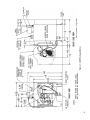
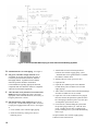
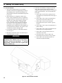
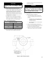
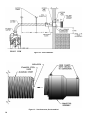
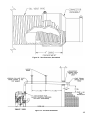
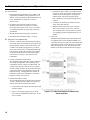
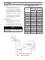
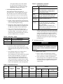
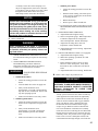
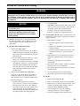
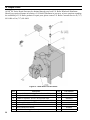
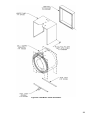
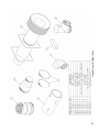
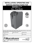
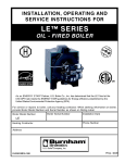
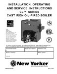
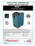
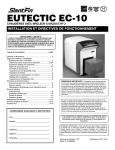
IN S TAL L AT ION , OP E R AT IN G AN D
S E R V IC E IN S T R U C T ION S F OR
L E ® D V S E R IE S
DIRECT VENT
OI L - F I R E D BOI L E R
As an ENERGY STAR® Partner, Burnham Hydronics has determined that the LEDV1, fired at the 0.60 GPH rate,
meets the ENERGY STAR guidelines for Energy efficiency established by the United States Environmental Protection Agency (EPA).
F o r s e rvi c e o r r e p a i rs to b o i le r, c a ll yo ur he a ti ng c o ntra c to r. W he n s e e k i ng i nfo rma ti o n o n
b o i le r, p ro vi d e B o i le r M o d e l Numb e r a nd S e ri a l Numb e r a s s ho wn o n Ra ti ng L a b e l.
B o i le r Mo d e l Num b e r
B o i le r S e ri a l Numb e r
Ins ta lla ti o n D a te
LE D V
He a ti ng C o ntra c to r
P ho ne Numb e r
A d d re s s
81433101R16-1/10
Price - $3.00
IMPORTANT INFORMATION - READ CAREFULLY
All boilers must be installed in accordance with National, State and Local Plumbing, Heating
and Electrical Codes and the regulations of the serving utilities. These Codes and Regulations
may differ from this instruction manual. Authorities having jurisdiction should be consulted
before installations are made.
In all cases, reference should be made to the following Standards:
USA BOILERS
A. Current Edition of American National Standard ANSI/NFPA 31, “Installation of Oil
Burning Equipment”, for recommended installation practices.
B. Current Edition of American National Standard ANSI/NFPA 211, “Chimneys, Fireplaces, Vents, and Solid Fuel Burning Appliances”, For Venting requirements.
C. Current Edition of American Society of Mechanical Engineers ASME CSD-1, “Controls and Safety Devices for Automatically Fired Boilers”, for assembly and operations of controls and safety devices.
D. All wiring on boilers installed in the USA shall be made in accordance with the National Electrical Code and/or Local Regulations.
CANADIAN BOILERS
A. Current Edition of Canadian Standards Association CSA B139, “Installation Code for Oil Burning Equipment", for recommended Installation Practices.
B. All wiring on boilers installed in Canada shall be made in accordance with the Canadian Electrical Code and/or Local Regulations.
The following terms are used throughout this manual to bring attention to the presence of hazards of various risk levels, or to
important information concerning product life.
DANGER
CAUTION
Indicates an imminently hazardous situation
which, if not avoided, will result in death, serious
injury or substantial property damage.
Indicates a potentially hazardous situation which,
if not avoided, may result in moderate or minor
injury or property damage.
WARNING
NOTICE
Indicates a potentially hazardous situation which,
if not avoided, could result in death, serious injury
or substantial property damage.
Indicates special instructions on installation,
operation, or maintenance which are important
but not related to personal injury hazards.
NOTICE
This boiler has a limited warranty, a copy of which is printed on the back of this manual.
It is the responsibility of the installing contractor to see that all controls are correctly installed and are operating
properly when the installation is complete. The warranty for this boiler is valid only if the boiler has been
installed, maintained and operated in accordance with these instructions.
DANGER
DO NOT store or use gasoline or other flammable vapors or liquids in the vicinity of this or any other
appliance.
If you smell gas vapors, DO NOT try to operate any appliance - DO NOT touch any electrical switch or use
any phone in the building. Immediately, call the gas supplier from a remotely located phone. Follow the gas
supplier's instructions or if the supplier is unavailable, contact the fire department.
WARNING
Boiler materials of construction, products of combustion and the fuel contain alumina, silica, heavy metals,
carbon monoxide, nitrogen oxides, aldehydes and/or other toxic or harmful substances which can cause
death or serious injury and which are known to the state of California to cause cancer, birth defects and
other reproductive harm. Always use proper safety clothing, respirators and equipment when servicing
or working nearby the boiler.
This boiler contains very hot water under high pressures. Do not unscrew any pipe fittings nor attempt
to disconnect any components of this boiler without positively assuring the water is cool and has no
pressure. Always wear protective clothing and equipment when installing, starting up or servicing this
boiler to prevent scald injuries. Do not rely on the pressure and temperature gauges to determine the
temperature and pressure of the boiler. This boiler contains components which become very hot when
the boiler is operating. Do not touch any components unless they are cool.
This boiler must be properly vented and connected to an approved vent system in good condition. Do
not operate boiler with the absence of an approved vent system.
This boiler needs fresh air for safe operation and must be installed so there are provisions for adequate
combustion and ventilation air.
The interior of the venting and air intake systems must be inspected and cleaned before the start of the
heating season and should be inspected periodically throughout the heating season for any obstructions.
Clean and unobstructed venting and air intake systems are necessary to allow noxious fumes that could
cause injury or loss of life to vent safely and will contribute toward maintaining the boiler's efficiency.
This boiler is supplied with controls which may cause the boiler to shut down and not re-start without
service. If damage due to frozen pipes is a possibility, the heating system should not be left unattended in
cold weather; or appropriate safeguards and alarms should be installed on the heating system to prevent
damage if the boiler is inoperative.
This boiler is designed to burn No. 2 fuel oil only. Do not use gasoline, crankcase drainings, or any oil
containing gasoline. Never burn garbage or paper in this boiler. Do not convert to any solid fuel (i.e.
wood, coal). Do not convert to any gaseous fuel (i.e. natural gas, LP/propane). All flammable debris,
rags, paper, wood scraps, etc., should be kept clear of the boiler at all times. Keep the boiler area clean
and free of fire hazards.
All boilers equipped with burner swing door have a potential hazard which if ignored can cause severe
property damage, personal injury or loss of life. Before opening swing door, turn off service switch to
boiler and disconnect two halves of Burner Swing Door Interlock wiring harness to prevent accidental
firing of burner outside the combustion chamber. Be sure to tighten swing door fastener completely and
reconnect two halves of Burner Swing Door Interlock when service is completed.
WARNING
Improper installation, adjustment, alteration, service or maintenance can cause property damage, personal
injury or loss of life. Failure to follow all instructions in the proper order can cause personal injury or
death. Read and understand all instructions, including all those contained in component manufacturers
manuals which are provided with the appliance before installing, starting-up, operating, maintaining or
servicing this appliance. Keep this manual and literature in legible condition and posted near appliance
for reference by owner and service technician.
This boiler requires regular maintenance and service to operate safely. Follow the instructions contained
in this manual.
Installation, maintenance, and service must be performed only by an experienced, skilled and knowledgeable
installer or service agency.
All heating systems should be designed by competent contractors and only persons knowledgeable in
the layout and installation of hydronic heating systems should attempt installation of any boiler.
Installation is not complete unless a pressure relief valve is installed into the tapping located on top of
appliance - See Water Piping and Trim Section of this manual for details.
It is the responsibility of the installing contractor to see that all controls are correctly installed and are
operating properly when the installation is completed.
This boiler is suitable for installation on combustible flooring. Do not install boiler on carpeting.
Do not tamper with or alter the boiler or controls.
Inspect flueways at least once a year - preferably at the start of the heating season. The inside of
the combustion chamber, the vent system and boiler flueways should be cleaned if soot or scale has
accumulated.
Oil Burner and Controls must be checked at least once a year or as may be necessitated.
Do not operate unit with jumpered or absent controls or safety devices.
Do not operate unit if any control, switch, component, or device has been subject to water.
Table of Contents
I. Pre-Installation.............................................................6
II. Unpack Boiler...............................................................7
III. Water Piping and Trim..................................................9
IV. Venting/Air Intake Piping...........................................12
V. Electrical and Sequence of Operations........................18
VI. Oil Piping...................................................................21
VII. System Start-up...........................................................23
VIII. Service and Cleaning...................................................29
IX. Repair Parts................................................................32
X. Appendix
Low Water Cut Off......................................................39
Figure 1: LEDV Packaged Boiler
Water Content: 6.1 gallons
I. Pre-Installation
A. INSPECT SHIPMENT carefully for any signs of
damage.
1. ALL EQUIPMENT is carefully manufactured,
inspected and packed. Our responsibility ceases
upon delivery of crated boiler to the carrier in good
condition.
2. ANY CLAIMS for damage or shortage in shipment
must be filed immediately against the carrier by the
consignee. No claims for variances from, or shortage
in orders, will be allowed by the manufacturer
unless presented within sixty (60) days after receipt
of goods.
B. LOCATE BOILER in front of final position before
removing crate. See Figure 1. Boiler's approximate
shipping weight is 325 pounds.
1. LOCATE so that vent pipe will be short and direct.
Refer to Section V. A., General Venting Guidelines.
2. BOILER IS SUITABLE FOR INSTALLATION
ON COMBUSTIBLE FLOOR. Boiler cannot be
installed on carpeting.
3. FOR BASEMENT INSTALLATION, provide a
solid base, such as concrete, if floor is not level, or if
water may be encountered on floor around boiler.
4. PROVIDE SERVICE CLEARANCE of at least 24”
at front of boiler for servicing.
5. For minimum clearances to combustible materials,
see Figure 2.
C. PROVIDE COMBUSTION AIR SUPPLY to
accommodate proper combustion of oil. Local and
national codes may apply and should be referenced.
1. In unconfined spaces (basement) in buildings of
conventional frame, brick, or stone construction,
infiltration normally is adequate to provide air for
combustion. An unconfined space is a space whose
volume is greater than or equal to 50 cubic feet
per 1000 BTUH of the combined input of all air
consuming appliances in the space.
2. In a confined space, combustion air may be ducted
directly from the outdoors to the burner. Refer to
Section IV for installation of air intake duct to the
burner.
D. VENTILATION AIR must be provided to maintain the
ambient temperature at safe limits. Local and national
codes may apply and should be referenced.
1. In unconfined spaces (basement) in buildings of
conventional frame, brick, or stone construction,
infiltration normally is adequate to provide air for
ventilation.
2. In confined spaces (closet, etc.) two permanent
openings, one near the top of the enclosure and one
near the bottom, shall be provided. Each opening
shall have a free area of not less than 1 sq. inch per
1000 BTUH of the total input of all appliances in the
space.
E. Do not install boiler where gasoline or other flammable
vapors or liquids, or sources of hydrocarbons (i.e.
bleaches, cleaners, chemicals, sprays, paint removers,
fabric softeners, etc.) are used or stored.
II. Unpack Boiler
CAUTION
Do not drop boiler. Do not bump boiler jacket
against floor.
A. REMOVE CRATE
1. Remove all fasteners at crate skid.
2. Lift outside container and remove all other inside
protective spacers and bracing. Remove vacuum
relief valve and miscellaneous trim bag containing
safety/relief valve, and pipe fittings.
B. REMOVAL OF BOILER FROM SKID
1. Boiler is secured to base with 2 bolts, 1 at left front
and 1 at right rear. Remove both bolts.
2. Tilt boiler, "walk" boiler backward, and set rear
legs down on floor. Tilt boiler backward, pull skid
forward and set front legs down on edge of skid.
Install close nipple, tee, and plug in return coupling.
See Section III and Figure 5. Point tee toward
permanent return location.
3. Tilt boiler backward and remove skid. Be careful not
to damage Burner or Jacket.
C. DETERMINE PROPER HINGE LOCATION FOR
BURNER SWING DOOR. Boiler is shipped with
hinges on left side. Approximately 12 inches are
required on the hinge side for burner clearance. If there
will be less than 12 inches from left side of boiler to
wall, move hinges to right side (refer to Paragraph D).
D. HINGE LOCATION CHANGE (if required) (refer to
Figure 3).
1. Pull 2 halves of Burner Swing Door Interlock apart.
Swing Door Interlock is connected to T-T terminals
on R7184P Control. Lift Honeywell R7184P Control
off of Burner Junction Box and disconnect wiring
harness from burner.
2. Remove 8 sheet metal screws from jacket. Remove
rear jacket box and bend both sides of Jacket
Wrapper up, see Figure 22.
3. Remove 2 (two) 5/16" - 18 x 3" long hex head cap
screws and flat washers from right side of door.
Remove 2 hairpin cotter pins and 2 hinge pins
from hinges on left side of door and remove Door
Assembly from boiler. Inspect Front and Rear Door
Insulation Pieces and Combustion Chamber Liner,
see Paragraph G.
4. Remove 4 hex nuts from bolts that attach hinges and
hinge spacers to left side of Tubesheet. Remove 4
hex head cap screws that attach hinges to door.
5. Attach 2 hinge brackets & spacers to Tubesheet and
2 hinge brackets to Door on right side of boiler. 3
Holes in each Hinge Bracket must line up with 3
matching holes in Spacer, Tubesheet or Door. See
Figure 3. Tighten hex nuts, bolts and screws by
hand only.
6. Replace door assembly. Hinge brackets attached to
door must rest on top of hinge brackets attached to
tubesheet. See Figure 3. Slide hinge pins through
hinges from top and install cotter pins. Close door
and install 5/16" - 18 x 3" long hex head cap screws
through flat washers and left side of door and into
tapped holes in tubesheet. Tighten all hex nuts,
bolts and screws. When door is installed properly, it
is parallel to Tubesheet when viewed from top and
sides.
7. Bend sides of Jacket Wrapper down and attach 2
Jacket Straps to 4 slots at bottom of Jacket Wrapper
sides with sheet metal screws. Install Rear Jacket
Box with 4 sheet metal screws. See Figure 22.
8. Connect wiring harness to burner Junction Box
and install Honeywell R7184P Control, see Wiring
Diagram, Figure 15 or 15A.
Reconnect Swing Door Interlock.
E. INSTALL BOILER CONTROL.
1. Pull bulb and capillary tube out of hole in back of
control. Insert bulb in immersion well on top of
boiler and secure control with set screw in control.
2. Secure flexible conduit to Jacket Wrapper side with
conduit clamp and sheet metal screw. Conduit must
be on same side of boiler as Swing Door hinges.
F. MOVE BOILER TO PERMANENT POSITION by
sliding or walking.
G. INSPECT FRONT AND REAR DOOR INSULATION AND COMBUSTION CHAMBER LINER
1. OPEN BURNER SWING DOOR on front of boiler.
Use flashlight to inspect insulation secured to
front and rear doors. Inspect ceramic fiber blanket
secured to bottom of combustion chamber. Inspect
inner and outer door gaskets. Replace any damaged
pieces.
Figure 2: Minimum Clearances to Combustible Materials
Figure 3: Proper Hinge Bracket Installation and Assembly
III. Water Piping and Trim
WARNING
Failure to properly pipe boiler may result in improper operation and damage to boiler or building.
Oxygen contamination of boiler water will cause corrosion of iron and steel boiler components, and
can lead to boiler failure. U.S. Boiler’s Standard Warranty does not cover problems caused by oxygen
contamination of boiler water.
A. Design and install boiler and system piping to
prevent oxygen contamination of boiler water.
1.
2.
3.
1.
2.
3.
4.
5.
There are many possible causes of oxygen
contamination such as:
Addition of excessive make-up water as a result of
system leaks.
Absorption through open tanks and fittings.
Oxygen permeable materials in the distribution
system.
In order to insure long product life, oxygen sources
should be eliminated. This can be accomplished by
taking the following measures:
Repairing system leaks to eliminate the need for
addition of make-up water.
Eliminating open tanks from the system.
Eliminating and/or repairing fittings which allow
oxygen absorption.
Use of non-permeable materials in the distribution
system.
Isolating the boiler from the system water by
installing a heat exchanger.
B. Connect System supply and return piping to boiler. See
Figures 5 and 7. Also consult I=B=R Installation and
Piping Guides. Maintain minimum ½ inch clearance
from hot water piping to combustible materials.
1. If this boiler is used in connection with refrigeration
systems, the boiler must be installed so that the
chilled medium is piped in parallel with the heating
boiler using appropriate valves to prevent the chilled
medium from entering the boiler, see Figure 6. Also
consult I=B=R Installation and Piping Guides.
2. If this boiler is connected to heating coils located
in air handling units where they may be exposed
to refrigerated air, the boiler piping must be
equipped with flow control valves to prevent gravity
circulation of boiler water during the operation of
the cooling system.
3. If boiler is used with an Alliance™ SL IndirectFired Domestic Water Heater, install the Alliance™
SL as a separate heating zone. Refer to the
Alliance™ SL Installation, Operating, and Service
Instructions for additional information.
4. Use a system bypass if the boiler is to be operated
in a system which has a large volume or excessive
radiation where low boiler water temperatures may
be encountered (i.e. converted gravity circulation
system, etc.).
CAUTION
Do not operate boiler
temperatures below 120°F.
with
return
water
The bypass should be the same size as the supply
and return lines with valves located in the bypass
and return line as illustrated in Figures 5 and 7 in
order to regulate water flow for maintenance of
higher boiler water temperature.
Set the by-pass and return valves to a half throttle
position to start. Operate boiler until the system
water temperature reaches its normal operating
range.
Adjust the valves to maintain 180°F to 200°F boiler
water temperature and greater than 120°F return
temperature. Adjust both valves simultaneously.
Closing the boiler return valve while opening
the by-pass valve will raise the boiler return
temperature. Opening the boiler return valve while
closing the by-pass valve will lower the boiler return
temperature.
5. A hot water boiler installed above radiation level
must be provided with a low water cutoff device as
part of the installation.
If a low water cut-off is required, it must be
mounted in the system piping above the boiler.
The minimum safe water level of a hot water boiler
is just above the highest water containing cavity of
the boiler; that is, a hot water boiler must be full of
water to operate safely.
WARNING
Safety (relief) valve discharge piping must be
piped near floor to eliminate potential of severe
burns. Do not pipe in any area where freezing
could occur. Do not install any shut-off valves,
plugs or caps.
C. Install Safety Relief Valve. See Figures 5 and 7.
Safety Relief Valve must be installed with spindle in
vertical position. Installation of the relief valve must
be consistent with the ANSI/ASME Boiler and Pressure
Vessel Code, Section IV.
Figure 5: Recommended Water Piping for Zone Valve Zoned Heating Systems
D. Install Drain Valve in return piping. See Figure 5.
E. Oil, grease, and other foreign materials which
accumulate in new hot water boilers and a new or
reworked system should be boiled out, and then
thoroughly flushed. A qualified water treatment
chemical specialist should be consulted for
recommendations regarding appropriate chemical
compounds and concentrations which are compatible
with local environmental regulations.
F. After the boiler and system have been cleaned and
flushed, and before refilling the entire system add
appropriate water treatment chemicals, if necessary, to
bring the pH between 7 and 11.
G. Fill entire heating system with water and vent air
from system. Use the following procedure on a Series
Loop System equipped with zone valves. (See Figure
5).
1. Close isolation valve in boiler supply piping.
2. Isolate all circuits by closing zone valves or balancing valves.
3. Attach a hose to hose bib located just below isolation valve in boiler supply piping. (Note
- Terminate hose in five gallon bucket at a suitable
floor drain or outdoor area).
4. Starting with one circuit, open zone valve.
5. Open hose bib.
6. Open fill valve (Make-up water line should be located directly above isolation valve in boiler supply piping).
7. Allow water to overflow from bucket until discharge
from hose is bubble free for 30 seconds.
8. Open zone valve to the second zone to be purged, then close the first. Repeat this step until all zones have been purged, but always have one zone open. At completion, open all zone valves.
9. Close hose bib, continue filling the system until the pressure gauge reads 12 psi. Close fill valve.
(Note - If make-up water line is equipped with
pressure reducing valve, system will automatically
fill to 12 psi.
10.Open isolation valve in boiler supply piping.
11.Remove hose from hose bib.
10
Figure 6: Recommended Piping for Combination Heating &
Cooling (Refrigeration) Systems
Figure 7: Recommended Water Piping for Circulator Zoned Heating Systems
11
IV. Venting / Air Intake Piping
A. General Guidelines
1. Vent system installation must be in accordance
with these instructions and applicable provisions of
local building codes. Contact local building or fire
officials about restrictions and installation inspection
in your area.
2. The LE®DV Series is designed as a Direct Vent
boiler. In this configuration, all air for combustion
is supplied directly to the burner from outdoors and
flue gases are vented directly outdoors (through
wall). See Figures 10 and 11. The LEDV may
be side-wall vented with combustion air supplied
from indoors. This configuration may be used in
installations where infiltration provides adequate air
for combustion and ventilation. Flue gases are still
vented directly outdoors (through wall).
3. For minimum clearances to combustible materials
refer to Figure 2.
4. Maximum wall thickness that vent terminal may be
installed through is 10 inches.
WARNING
DO NOT locate vent terminal where exposed to
prevailing wind. Moisture and ice may form on
surfaces around vent termination. To prevent
deterioration, surfaces should be in good repair
(sealed, painted, etc.).
12
5. Locate the vent terminal so vent pipe is short and
direct, and at a place on the exterior wall that
complies with the minimum distances as specified in
Figure 8 and listed below. The vent terminal must
be located:
a. Not less than 12 inches above grade plus snow
accumulation (as measured to the nearest edge of
terminal).
b. Not less than 3 feet to center of terminal above
any forced air inlet located within 10 feet.
c. Not less than 1 foot to center of terminal
horizontally from any door, window or gravity
air inlet.
d. Not less than 7 feet to center of terminal above a
public walkway.
e. Not less than 3 feet to center of terminal from an
inside corner of an L-shaped structure.
f. Not less than 1 foot from nearest surface of
terminal to a roof soffit.
g. Not directly above, or not less than 6 feet
horizontally from an oil tank vent or gas meter.
h. Not less than 2 feet from nearest surface of
terminal to an adjacent building.
Figure 8: Vent Terminal Location
Components of this kit are listed in the Repair Parts
Section of this manual.
CAUTION
Operation of boiler with improperly adjusted
burner may result in soot damage to side of
house.
6. Intake Terminal Location (Direct Vent only) Locate Air Intake Terminal not less than 12 inches
to the left, right, or bottom of the vent terminal. Do
not locate air intake terminal above vent terminal.
Intake terminal must be at least 12 inches above
grade plus snow accumulation; at least 1 foot from a
roof soffit; at least 3 feet from an inside corner of an
L-shaped structure. See Figure 9.
7. The LEDV must be vented with 4" Z-Flex Direct
Oil™ Vent. 20 feet is the maximum vent length
allowed. The vent pipe is available in 5, 10, 15, and
20 foot lengths. Table 1 lists vent part numbers.
Table 1: Vent Pipe Part Numbers
DANGER
Vent pipe may not be spliced. Do not drill through
vent pipe. Do not operate boiler if vent pipe has
been crushed. Vent pipe must be completely
sealed. Do not operate boiler if vent pipe insulation
sleeve is damaged, frayed or missing.
B. Vent Installation (Direct Vent and Side-Wall Vent)
1. Install Vent Terminal. See Figure 10.
a. After determining the location from previous
Section, cut an opening in the wall for the vent
terminal.
• Combustible wall: 8 inches diameter hole
is required to maintain a 1 inch clearance to
combustible materials.
• Non-combustible wall: 6½ inches diameter
4" Direct Oil™ Vent Pipe
hole is required.
Pipe Length
Part No.
5 Ft.
8113302
b. Secure 10" square trim plate to outside wall.
10 Ft.
8113303
15 Ft.
8113304
c. Insert the vent terminal through the opening until
the stop bead rest against the trim plate.
20 Ft.
8113305
d. Slide the 10" square inside trim plate assembly
(fitted with gear clamp) onto the terminal pipe.
8. The vent system must be completed with the Direct
Oil™ Vent Kit, which is shipped with the boiler.
Figure 9: Intake Terminal Location
13
Figure 10: Vent Installation
Figure 11: Vent Connector, Un-Assembled
14
Figure 12: Vent Connector, Assembled
Figure 13: Air Intake Installation
15
e. Secure the inside trim plate to inside wall.
f. Tighten the gear clamp to the terminal pipe.
g. Seal all external joints with a weatherproof
caulk.
b. Avoid any sags or dips in vent pipe.
C. Air Intake Installation (Direct Vent only)
See Figure 13.
WARNING
2. Cut vent pipe to length with a hack saw.
3. Install Vent Connector/Appliance Adaptor. See
Figures 11 and 12.
a. Apply a continuous bead of high temperature
adhesive/sealant (supplied with boiler) around
outside of corrugated pipe of vent connector.
b. Twist vent connector into end of vent pipe.
Turn the connector counter-clockwise until it is
engaged approximately 4 inches into the inner
vent pipe and the outer collar of the connector
overlaps the outside of the vent pipe.
c. Tighten the gear clamp on the outer collar of the
connector.
d. Repeat steps a. through c. with the appliance
adapter.
4. Connect vent pipe to boiler.
a. Apply a continuous bead of high temperature
adhesive/sealant (supplied with boiler) to inside
of appliance adapter (approximately ½ inch from
end).
b. Slip appliance adapter over boiler flue collar and
tighten gear clamp.
5. Connect vent pipe to terminal.
a. Carefully slide insulation sleeve over vent
connector and vent pipe until gear clamp on
small end of connector can be accessed.
WARNING
Do not operate LEDV with barometric damper in
vent. Do not connect venting to chimney.
b. Apply a continuous bead of high temperature
adhesive/sealant (supplied with boiler) on inside
of cent connector (approximately ½ inch from
end).
Read, understand and follow combustion air
instruction restrictions contained in the PreInstallation Section of this manual.
1. General
a. Use 4 inch diameter single wall metal pipe and
fittings available at most heating distributors.
Maximum allowable air intake length is 40
equivalent feet. Each elbow is equal to 6
equivalent feet.
b. Start at Burner. Work toward air intake terminal.
c. Maintain minimum of ¼ inch per foot slope in
horizontal run to air intake terminal. Slope down
toward air intake terminal.
d. Seal all joints gas-tight, using silicone caulk or
self-adhesive aluminum tape.
2. After determining location, cut a hole in the wall to
accept 4 inch air intake pipe.
3. Remove the black plastic inlet cover from the right
side of the Beckett AFII burner.
4. Mount the vacuum relief valve tee assembly or 90°
elbow into the burner inlet ring. See Figure 13.
a. Secure with at least three (3) sheet metal screws
evenly spaced around the burner inlet ring.
b. Assemble the vacuum relief valve balance
weight onto the gate. Refer to the vacuum relief
valve manufacturer's instructions.
c. Mount the vacuum relief valve into the tee and
fasten with a screw and nut in collar tabs. To
ensure proper operation, the gate must be level
across the pivot point and plumb. Refer to
vacuum relief valve manufacturer's instructions.
c. Clip connector over vent terminal until it is fully
engaged. Then tighten gear clamp.
5. Install remainder of air intake, securing each joint
with at least three (3) sheet metal screws evenly
spaced.
d. Slide insulation sleeve over terminal connection
so that connector is completely covered.
WARNING
e. Secure each end of insulation sleeve with the
gear clamps provided.
6. Secure vent pipe in position with pipe straps.
a. All horizontal runs must rise at least ¼ inch per
foot toward vent terminal.
16
Do not reduce size of air intake pipe.
Do not locate air intake termination where natural
convention or wind conditions may cause the
boiler exhaust gases to be drawn into the air
intake.
6. Install air intake terminal. See Figure 13.
7. Seal all external joints with weatherproof caulk.
WARNING
Do not locate air intake where petroleum distillates,
CFC's, detergents, volatile vapors or any other
chemicals are present. Severe boiler corrosion
and failure will result.
D. Air Intake Installation (Indoor Air for Combustion)
1. Remove the black plastic inlet cover from the right
side of the Beckett AFII burner.
2. Attach the Air Intake Terminal directly to the burner
intake collar.
3. Discard the Vacuum Relief Valve.
Alternate to 1., 2. and 3.:
Keep the black plastic inlet cover in place and
discard the Air Intake Terminal and the Vacuum
Relief Valve.
WARNING
Do not locate air intake termination into a crawl
space or under a deck that also includes the
vent termination, regardless of distance between
terminations.
17
V. Electrical and Sequence of Operations
A. ELECTRICAL
1. Install wiring and ground boiler in accordance with
requirements of authority having jurisdiction, or in
absence of such requirements the National Electrical
Code, ANSI/NFPA 70, and/or the CSA C22.1
Electric Code.
2. A separate electrical circuit must be run from
the main electrical service with an over-current
device/disconnect in the circuit. A service switch is
recommended and may be required by some local
jurisdictions.
3. Wiring should conform to Figures 15 and 15A.
4. Thermostat heat anticipator setting = 0.3 amp.
B. SEQUENCE OF OPERATIONS
1. General. A call for heat by the thermostat energizes
the L7248C limit control which in turn energizes the
R7184P primary control to turn on the burner. The
circulator will operate as long as there is a call for
heat. If the call for heat is not satisfied and the high
limit setting is reached, the circulator will continue
to operate, and the burner will stop until the high
limit circuit is closed by a drop in boiler water
temperature.
c. If the burner ignites within 15 seconds from the
time the oil valve opens and the CAD cell senses
a flame, the electronic ignitor is de-energized
and the burner will operate until the call for
heat is satisfied or the setting of the high limit is
reached.
d. A manual reset button is provided to reset the
safety switch after lockout.
e. When the call for heat ends, or the CAD cell
fails to sense a flame, the oil valve will close.
The combustion blower will continue to operate
for a postpurge period of approximately two (2)
minutes.
4. CAD Cell.
The Beckett AFII burners used on the LEDV Series
are supplied with a C554A Cadmium Sulfide (cad
cell) Flame Detector to monitor the burner flame and
shut down the burner on ignition failure or on flame
failure during the run cycle. On either failure, the
manual reset button on the R7184P will be tripped.
2. L7248C Combination Limit control.
The switching action within the L7248C control has
one setting, the high limit. The switching relay is
controlled by the low voltage room thermostat. On
a call for heat, the relay contacts close to complete
the line voltage circulator circuit and also the burner
circuit if the boiler water temperature is below the
high limit setting. The high limit switch shuts off
the burner if boiler water temperature exceeds the
high limit setting. See Figure 14.
3. R7184P Oil Primary Control.
The R7184P operates the oil burner motor, solenoid
oil valve, and the electronic ignitor in response to a
call for heat from the L7248C limit control.
a. A call for heat will energize the burner motor and
electronic ignitor.
b. After a 15 second pre-purge period, in which
time a draft is established in the flueways, the oil
valve is opened.
18
Figure 14: L7248/L7224 Setpoint and Differential
Switching Action
19
Figure 15: Beckett Burner Schematic Wiring Diagram
Figure 15A: Riello BF Burner Schematic Wiring Diagram
Refer to the information supplied by the burner manufacturer for any additional burner information.
20
VI. Oil Piping
A. General
1. Use flexible oil line(s) so that Swing Door can be
opened without disconnecting oil supply.
2. A supply line fuel oil filter is recommended as a
minimum for all firing rates but a pleated paper fuel
oil filter is recommended for the lowest (.6 GPH)
firing rate application to prevent nozzle fouling.
Table 2: Single-Stage Units (3450 RPM) Two Pipe Systems
Lift "H"
Maximum Length of Tubing
"H" + "R"
3/8" OD
1/2" OD
Tubing (3 GPH) Tubing (3 GPH)
3. Use Flared fittings only. Do not use compression
fittings.
0'
84'
100'
1'
78'
100'
4. Use of a high efficiency micron oil filter (Garber
or equivalent) in addition to conventional filter is
highly recommended.
2'
73'
100'
3'
68'
100'
4'
63'
100'
5'
57'
100'
6'
52'
100'
7'
47'
100'
8'
42'
100'
9'
36'
100'
10'
31'
100'
11'
26'
100'
12'
21'
83'
13'
---
62'
14'
---
41'
B. Single-pipe Oil Lines.
1. Standard burners are provided with single-stage
3450 rpm fuel units with the bypass plug removed
for single-pipe installations.
2. The single-stage fuel unit may be installed singlepipe with gravity feed or lift. Maximum allowable
lift is 8 feet. See Figure 16.
NOTICE
Single-pipe installations must be absolutely airtight
or leaks or loss of prime may result. Bleed line and
fuel unit completely.
Figure 16: Single-Pipe Installation
21
Figure 17: Two-Pipe Installation
C. Two-Pipe Oil Lines.
1. For two-pipe systems where more lift is required,
the two-stage fuel unit is recommended. Table
2 (single-stage) and Table 3 (two-stage) show
allowable lift and lengths of 3/8-inch and ½-inch
OD tubing for both suction and return lines. Refer
to Figure 17.
22
Table 3: Two-Stage Units (3450 RPM) Two Pipe Systems
Lift "H"
Maximum Length of Tubing
"H" + "R"
3/8" OD
1/2" OD
Tubing (3 GPH) Tubing (3 GPH)
0'
93'
100'
2'
85'
100'
4'
77'
100'
6'
69'
100'
8'
60'
100'
10'
52'
100'
12'
44'
100'
14'
36'
100'
16'
27'
100'
18'
---
76'
VII. System Start-up
WARNING
All boilers equipped with burner swing door have a potential hazard which can cause severe property damage,
personal injury or loss of life if ignored. Before opening swing door, turn off service switch to boiler to
prevent accidental firing of burner outside the combustion chamber. Be sure to tighten swing door fastener
completely when service is completed.
A. ALWAYS INSPECT INSTALLATION BEFORE
STARTING BURNER.
B. FILL HEATING SYSTEM WITH WATER. Refer to
Section III, G.
C. CHECK CONTROLS, WIRING AND BURNER to be
sure that all connections are tight and burner is rigid,
that all electrical connections have been completed and
fuses installed, and that oil tank is filled and oil lines
have been tested.
D. LUBRICATION — Follow instruction on burner and
circulator label to lubricate, if oil lubricated. Most
motors currently used on residential type burners
employ permanently lubricated bearings and thus do
not require any field lubrication. Water lubricated
circulators do not need field lubrication.
Figure 18: L7248 Circuit Board Layout Horizontal Mount
· °F -- °C (Toggle)
Then press the UP and/or DOWN buttons
to move the set point to the desired value.
After 60 seconds without any button inputs,
the control will automatically return to the
READ mode.
ii. Display:
In the RUN mode, the Aquastat will
flash “bt” (boiler temp.) followed by the
temperature (i.e., 220), followed by °F or
°C.
To read boiler settings, press the ‘I’ key to
read the parameter of interest. For example,
press I (HL) High Limit is displayed,
followed by a three-digit number, i.e., 220,
followed by °F or °C.
See Figure 19 for Display Readout
Definitions.
Do not over-lubricate. This can cause as much trouble
as no lubrication at all.
E. Adjust control settings with burner
service switch turned “ON” and room thermostat set
10° below room temperature.
1. Adjustment and display modes of the L7248/
L7224 Oil Electronic Aquastat Controller.
a. On the L7248/L7224, the overall range of the
High Limit is from 180°F to 240°F (82°C to
116°C).
b. Set the High Limit (designated HL) on the
L7248/L7224 Aquastat Control at 180°F. This
temperature setting may be varied to suit
requirements of installation. Differential is fixed
at 15°F.
i.
Adjusting Settings:
To discourage unauthorized changing of
Aquastat settings, a procedure to enter the
adjustment mode is required. To enter the
adjustment mode, press the UP, DOWN,
and I buttons (see Figure 18) simultaneously
for three (3) seconds. Press the ‘I’ button
until the feature requiring adjustment is
displayed (press the “I” button again and
will display LL (Low Limit on L7224):
· High Limit
Text
bt
HL err f
c LL
Display
Description
Shows
Boiler Temperature
High Limit
Error Code
Degrees Fahrenheit
Degrees Celsius
Low Limit
Figure 19: Display Readout Definitions
23
After approximately 60 seconds without
any key pressed, the display will enter a
dim display mode. To return to the bright
display mode, simply press any key.
2. Control Operating Characteristics
The L7248/L7224 can be in any three (3)
operational states: Normal, High-Limit and Error.
The controller moves back and forth from HighLimit to Normal state as part of normal operation.
The controller will enter the Error state when there
is an abnormal condition. The operating states are:
a. Normal: Boiler temperature has gone below the
high limit setting (minus the differential) and has
not exceeded the high limit setting.
Table 5: L7248/L7224 Controller Operating Sequence
A c ti o n
The rmos ta t
ca lls fo r
he at
C i rcula to r a nd burner turn o ff.
E rro r
co nd i ti o n
If a n e rror co nd i ti o n i s d e te cte d , a ll outp uts
a re shut d o wn. B urner i s o ff. C o ntro l
co nti nue s to functi o n and re starts whe n
e rro r i s co rre cte d .
D uri ng the e rro r che ck se q ue nce , the
syste m che cks for d ri ft i n the se nso r a nd
co rro si o n i n the connecti o ns.
setting. The high limit switch shuts off the burner
if boiler water temperature exceeds the high limit
setting. The circulator will continue to operate
as long as the thermostat is calling for heat. The
high limit automatically resets after the water
temperature drops past the setpoint and through
the differential.
Table 4: LED Error Codes
Cause/Action
Sensor fault; check sensor.
Err2
ECOM fault; check EnviraCom™ wiring.
Err3
Hardware fault’ replace control.
d. Low-Limit: Boiler temperature has gone
below the low limit setting (minus the low limit
differential) and has not gone above the low limit
setting.
F. BURNER START-UP
WARNING
Do not attempt to start the burner when excess
oil has accumulated in the chamber, when boiler
is full of vapor or when combustion chamber is
very hot.
e. The operating sequence for L7248/L7224 is
described below and shown in Table 5.
C i rcula to r sta rts.
B o i le r te mp e ra ture i s check ed . B urne r
re sta rts whe n the water te mp e ra ture i s
b e lo w hi gh li mi t se tti ng .
The rmos ta t
i s sa ti sfi e d
c. Error: The controller has detected an error
condition (e.g., open sensor) and has shut down
the burner output. The controller continues to
monitor the system and automatically restarts if
the error condition clears. See Table 4.
Err1
S ys te m Re s p o ns e
B o i le r
B urne r i s turne d off. B urner re sta rts whe n
e xce e ds the the wa te r te mp e ra ture d ro ps be lo w the
hi g h li mi t
hi g h li mi t s etti ng mi nus the d i ffe re nti a l.
b. High-Limit: Boiler temperature has gone above
the high limit setting and has not dropped below
the high limit setting (minus the differential).
Error Code
1. VERIFY burner settings.
a. Refer to Table 6 for Beckett Burner Settings.
Refer to Table 6A for Riello BF Burner Settings.
The switching action in the L7248/L7224 control
has one setting, the high limit, see Figure 14.
The switching relay is controlled by the low
voltage room thermostat. On a call for heat, the
relay contacts make to complete the line voltage
circulator circuit and also the burner circuit if the
boiler water temperature is below the high limit
b. Check electrodes to comply with dimensions
shown in Figure 20A. For adjustment, loosen the
electrode clamp screw and slide/rotate electrodes
as needed. Securely re-tighten the clamp screw
when finished.
Table 6: Beckett AFII Burner
Boiler
Model
Firing Rate
(GPH)
Burner
Model
Air Tube
Combination
Delavan
Nozzle
LEDV1
0.60
AFII 85
HLX50HD
LEDV2
1.00
AFII 150
LEDV3
1.25
AFII 150
24
Settings
Air
Head
(stop screw)
Pump Pressure
(PSIG)
0.50 x 70°B
2.5
#2
140
HLX50HE
0.85 x 60°B
3.5
#3
140
HLX50HE
1.00 x 60°B
4.0
#5
140
Table 6A: Riello BF Burner Settings
Settings
Boiler
Model
Firing Rate
(GPH)
Burner
Model
Delavan Oil
Nozzle
Air Gate
Pump Pressure
(PSIG)
Turbulator
LEDV1
0.60
BF3
0.50 - 60° A
4.0
145
0
LEDV2
1.00
BF5
0.85 - 60° A
5.0
145
1.0
LEDV3
1.25
BF5
1.00 - 60° A
6.5
145
3.0
Figure 20A: Electrode Tip Gap & Spacing
c. Upon reinstallation of the nozzle line assembly,
check that head/air plate setting number pointer
lines up with a number on the scale, which
matches a value shown in Table 6 for a particular
boiler/burner model.
2. Open all shut-off valves in the oil supply line to the
burner.
8. INSTALL PRESSURE GAUGE
a. Either, remove plastic hose and oil pump vent
fitting, then, install a reliable pressure gauge
into vent fitting port, or install the gauge into the
nozzle port. See Figure 20B.
3. Attach a plastic hose to fuel pump vent fitting and
provide a container to catch the oil.
4. REMOVE GAUGE PORT PLUG from fuel pump
and install pressure gauge.
5. REMOVE TEST PLUG IN FLUE COLLAR.
6. Close the service switch to start the burner. If the
burner does not start immediately, check the manual
overload switch on the motor, if so equipped, and
the safety switch of the burner primary control.
WARNING
Very hot flue gases come out of sight hole when
boiler is operated without sight plug installed.
Always wear proper eye protection.
7. Bleed the fuel unit when the burner motor starts
rotating. To bleed, loosen the vent fitting (with
plastic hose attached) and catch the oil in an empty
container. Continue to bleed for 15 seconds after oil
is free of air bubbles. Tighten the vent fitting when
all the air is purged. NOTE: Bleeding might not be
necessary with a two pipe system. When vent fitting
is closed, burner flame should start immediately.
Figure 20B: Checking / Adjusting Fuel
Pump Pressure
9. CHECK / ADJUST OIL PRESSURE
a. Check oil pressure to correspond to a specified
value for a particular LEDV boiler model. Refer
to Table 6.
25
b. For adjustment, locate oil pressure adjusting
screw and turn screw to obtain oil pressure
specified.
10. ADJUST AIR SETTING on burner for alight orange
colored flame. Flame should be solid and compact.
Use smoke tester and adjust air for a minimum
smoke (not to exceed #1) with a minimum excess
air. Make final check using suitable instrumentation
to obtain CO2 of 11.5% to 12%. These settings
will assure a safe and efficient operating condition.
If flame appears stringy instead of solid fire, try
another nozzle of the same type.
11. TURN "OFF" BURNER BY OPENING SERVICE SWITCH. Remove pressure gauge. Install gauge port plug and tighten. Re-start burner.
12. HINTS ON COMBUSTION
iii. Filter connection leaks.
iv. Tank connection leaks.
There are various test kits available to trace
air leaks, such as electronic sight glasses.
Follow the manufacturers' instructions to
find air leaks.
The following actions can eliminate air leaks:
i.
Bleed pump as detailed in System Start-Up
Section of this manual.
ii. Replace flare fittings.
iii. Replace oil supply line.
iv. Repair oil filter leaks.
v. Replace or repair tank fittings.
a. NOZZLES — Although the nozzle is a relatively
inexpensive device, its function is critical to
the successful operation of the oil burner. The
selection of the nozzle supplied with the LEDV
boiler is the result of extensive testing to obtain
the best flame shape and efficient combustion.
Other brands of the same spray angle and spray
pattern may be used but may not perform at the
expected level of CO2 and smoke. Nozzles are
delicate and should be protected from dirt and
abuse. Nozzles are mass-produced and can vary
from sample to sample. For all of those reasons a
spare nozzle is a desirable item for a serviceman
to have.
e. GASKET LEAKS — If 11.5 to 12.5% CO2 with
a #1 smoke cannot be obtained in the breeching,
look for air leaks around the flue collar. Such
air leaks will cause a lower CO2 reading in the
breeching. The smaller the firing rate the greater
effect an air leak can have on CO2 readings.
b. FLAME SHAPE — Looking into the
combustion chamber through the flame plug
hole, the flame should appear straight with
no sparklers rolling up toward the top of the
chamber. If the flame drags to the right or left,
sends sparklers upward or makes wet spots on
the rear door insulation piece, the nozzle should
be replaced. If the condition persists look for
fuel leaks, air leaks, water or dirt in the fuel as
described below.
g. WATER — Water in the fuel in large amounts
will stall the fuel pump. Water in the fuel in
smaller amounts will cause excessive wear on
the pump, but more importantly water doesn’t
burn. It chills the flame and causes smoke and
unburned fuel to pass out of the combustion
chamber and clog the flueways of the boiler.
c. FUEL LEAKS — Any fuel leak between the
pump and the nozzle will be detrimental to good
combustion results. Look for wet surfaces in the
air tube, under the transformer, and around the
air inlet. Any such leaks should be repaired as
they may cause erratic burning of the fuel and in
the extreme case may become a fire hazard.
d. AIR LEAKS — Any such leaks should be
repaired, as they may cause erratic burning of
the fuel and in extreme cases may become a fire
hazard.
There are many possible causes of air leaks in oil
lines such as:
i. Fitting leaks due to mis-flared tubing or
damaged fitting.
26
ii. Fuel line leak due to crushed or bent tubing.
f. DIRT — A fuel filter is a good investment.
Accidental accumulation of dirt in the fuel
system can clog the nozzle or nozzle strainer and
produce a poor spray pattern from the nozzle.
The smaller the firing rate, the smaller the slots
become in the nozzle and the more prone to
plugging it becomes with the same amount of
dirt.
h. COLD OIL — If the oil temperature approaching
the fuel pump is 40°F or lower poor combustion
or delayed ignition may result. Cold oil is harder
to atomize at the nozzle. Thus, the spray droplets
get larger and the flame shape gets longer. An
outside fuel tank that is above grade or has fuel
lines in a shallow bury is a good candidate for
cold oil. The best solution is to bury the tank and
lines deep enough to keep the oil above 40°F.
i. HIGH ALTITUDE INSTALLATIONS — Air
settings must be increased at higher altitudes.
Use instruments and set for 11.5 to 12.5% CO2.
j. START-UP NOISE — Late ignition is the
cause of start-up noises. If it occurs recheck for
electrode settings, flame shape, air or water in
the fuel lines.
k. SHUT DOWN NOISE — If the flame runs out
of air before it runs out of fuel, an after burn
with noise may occur. That may be the result
of a faulty cut-off valve in the fuel pump, or it
may be air trapped in the nozzle line. It may take
several firing cycles for that air to be fully vented
through the nozzle. Water in the fuel or poor
flame shape can also cause shut down noises.
NOTICE
CHECK TEST PROCEDURE. A very good test for
isolating fuel side problems is to disconnect the
fuel system and with a 2 foot length of tubing, fire
out of an auxiliary five gallon pail of clean, fresh,
warm #2 oil from another source. If the burner runs
successfully when drawing out of the auxiliary
pail then the problem is isolated to the fuel or fuel
lines being used on the jobsite.
G. TEST CONTROLS
WARNING
Before installation of the boiler is considered
complete, the operation of all boiler controls must
be checked, particularly the primary control and
high limit control.
c. Simulate power failure:
• Follow the starting procedure to turn on the
burner.
• With the burner running, turn off the power
to the system by tripping the circuit breaker
or removing the fuse.
• Burner should stop.
• Restore power. Burner should start.
d. If system does not operate as described, go to the
TROUBLESHOOTING AND MAINTENANCE
section.
3. VERIFY HIGH LIMIT OPERATION.
a. Adjust thermostat to highest setting.
b. Observe temperature gauge. When temperature
is indicated, adjust limit to setting below
observed temperature. Burner should stop.
c. Adjust limit to setting above observed
temperature. Burner should start.
d. Adjust thermostat to lowest setting. Adjust limit
to desired setting.
4. CHECK LOW WATER CUTOFF (if so equipped).
1. CHECK THERMOSTAT OPERATION. Raise and
lower thermostat setting as required to start and stop
burner.
a. Adjust thermostat to highest setting.
2. VERIFY PRIMARY CONTROL SAFETY
FEATURES using procedures outlined in
Instructions furnished with control (See back of
Control Cover) or Instructions as follows:
c. Burner should stop when water level drops
below low water cutoff probe. Verify limit,
thermostat or other controls have not shut off
boiler.
WARNING
FOR HEATING SERVICEMAN
ONLY
a. Simulate flame failure:
b. With boiler operating, open drain valve and
slowly drain boiler.
d. Adjust thermostat to lowest setting. Refill boiler.
H. Boiler is now ready to be put into service.
• Follow the starting procedure to turn on the
IMPORTANT
• Close the hand valve in the oil supply line.
• Safety switch should lock out in
IF, DURING NORMAL OPERATION, IT IS
NECESSARY TO ADD WATER MORE FREQUENTLY
THAN ONCE A MONTH, CONSULT A QUALIFIED
SERVICE TECHNICIAN TO CHECK YOUR
SYSTEM FOR LEAKS.
burner.
approximately 15 seconds. Ignition should
stop and oil valve should close. Blower will
stop after postpurge period.
• Push red reset button to reset safety switch.
b. Simulate ignition failure:
• Follow the starting procedure to turn on the
burner, but do not open the oil supply hand
valve.
• Safety switch should lock out in
approximately 15 seconds. Ignition and
motor should stop and oil valve should
close.
• Push red reset button to reset safety switch.
A leaky system will increase the volume of make-up
water supplied to the boiler which can significantly
shorten the life of the boiler. Entrained in make-up
water are dissolved minerals and oxygen. When the
fresh, cool make-up water is heated in the boiler
the minerals fall out as sediment and the oxygen
escapes as a gas. Both can result in reduced boiler
life. The accumulation of sediment can eventually
isolate the water from contacting the steel. When this
happens the steel in that area gets extremely hot and
eventually cracks. The presence of free oxygen in the
boiler creates a corrosive atmosphere which, if the
concentration becomes high enough, can corrode the
27
steel through from the inside. Since neither of these
failure types are the result of a manufacturing defect
the warranty does not apply. Clearly it is in everyone’s
best interest to prevent this type of failure. The
maintenance of system integrity is the best method to
achieve this.
28
Section VIII: Service and Cleaning
WARNING
All boiler cleaning must be completed with burner service switch turned off. Boilers equipped with burner
swing door have a potential hazard which can cause severe property damage, personal injury or loss of
life if ignored. Before opening swing door, turn off service switch to boiler to prevent accidental firing of
burner outside the combustion chamber. Be sure to tighten swing door fasteners completely when service
is completed.
NOTICE
BURNER SHUTDOWN: Open Service Switch
to turn off burner.
Manual Oil Supply Valve should be closed
and Electric Service to boiler turned off if
boiler will not be operated for an extended
period of time.
A. General. Inspection, service and cleaning should
be conducted annually. Turn off electric power and
close oil supply valve while conducting service or
maintenance.
B. Firetubes and Combustion Chamber.
1. CLEAN THE FIRETUBES
a. For access to fireside of boiler, pull two halves
of Burner Swing Door Interlock wiring harness
apart, remove fasteners holding door closed and
open swing door.
b. Prior to cleaning boiler, lay a protective cloth or
plastic over combustion chamber liner.
c. Using a 1 1/2" diameter wire brush (30" handle),
clean firetubes. Measure 15" from end of brush
opposite handle, and mark handle. DO NOT
allow this mark to go past front end of firetube
during cleaning, or brush will hit rear door
insulation piece.
2. CLEAN THE COMBUSTION CHAMBER
Using wire or fiber bristle brush, clean inside of
combustion chamber. DO NOT let brush hit rear
door insulation piece or combustion chamber liner.
3. AFTER CLEANING
a. Vacuum debris inside bottom of rear door,
remove protective cloth, and vacuum remaining
fireside of boiler as necessary. BE CAREFUL
not to damage liner or rear door insulation piece.
Inspect front and rear door insulation pieces,
front door gaskets and combustion chamber liner
for damage. Replace any damaged pieces.
4. CLOSE BOILER
CAUTION: Do not start burner unless burner swing
door is securely closed. Close door, install fasteners,
and tighten securely. Door should be parallel
to tubesheet when viewed from top and sides.
Reconnect two halves of Swing Door Interlock.
C. Vent/Air Intake System. Inspect for obstructions, soot
accumulation, proper support, and deterioration of pipe,
fittings, and joints.
1. Inspect inside of vent pipe.
a. Disconnect appliance adapter from boiler flue
collar.
b. Remove any obstructions and clean with a wire
brush as required.
c. Reconnect appliance adapter to boiler flue collar
as detailed in Section IV: Venting/Air Intake
Piping.
2. Clean terminal screens. Terminals must be free of
obstruction, undamaged, with screens securely in
place.
3. Terminal and wall thimbles (if used) must be
weather-tight.
4. Pipe must be full round shape, and show no damage
from impact or excessive temperature.
5. Pipe must be supported at minimum 5 foot intervals
and must not sag.
6. All vent joints must be secure and watertight.
7. All air intake joints must be secure and airtight.
D. Burner.
1. Replace the oil supply line filter.
2. Remove and clean the pump strainer (if applicable).
3. Replace the nozzle with an equivalent nozzle. Refer
to Table 6 for Beckett Burner Settings. Refer to
Table 6a for Riello BF Burner Settings.
4. Clean and inspect the electrodes for damage,
replacing any that are cracked or chipped.
5. Clean the combustion head of all lint and soot.
29
6. Inspect the transformer cables and connectors.
7. Remove and clean the cad cell.
8. Clean the blower wheel and the air control of any
lint.
9. Check all wiring for secure connections or insulation
breaks.
10.Re-adjust the burner as detailed in Section VII:
System Start-up, Paragraph F.
E. Controls. Test Controls for proper operation as
detailed in Section VII: System Start-up, Paragraph G.
F. Low water cutoff (if so equipped).
1. Float Type
a. Monthly Blowoff. During the heating season, if
an external float type low water cutoff is on the
boiler, the blow off valve should be opened once
a month (use greater frequency where conditions
warrant), to flush out the sediment chamber so
the device will be free to function properly.
30
b. Annual Service. Float type low water cutoffs
should be dismantled annually by qualified
personnel, to the extent necessary to insure
freedom from obstructions and proper
functioning of the working parts. Inspect
connecting lines to boiler for accumulation of
mud, scale, etc., and clean as required. Examine
all visible wiring for brittle or worn insulation
and make sure electrical contacts are clean
and that they function properly. Give special
attention to solder joints on bellows and float
when this type of control is used. Check float
for evidence of collapse and check mercury bulb
(where applicable) for mercury separation or
discoloration.
2. Probe Type (Annual Service). Probe type LWCO
should be removed once a year, examined and
cleaned of any dirt accumulations to assure proper
operations. Do not attempt to repair mechanisms
in the field. Complete replacement mechanisms,
including necessary gaskets and installation
instructions, are available from the manufacturer.
Important Product Safety Information
Refractory Ceramic Fiber Product
Warning:
The Repair Parts list designates parts that contain refractory ceramic fibers
(RCF). RCF has been classified as a possible human carcinogen. When
exposed to temperatures about 1805°F, such as during direct flame contact,
RCF changes into crystalline silica, a known carcinogen. When disturbed as a
result of servicing or repair, these substances become airborne and, if inhaled,
may be hazardous to your health.
AVOID Breathing Fiber Particulates and Dust
Precautionary Measures:
Do not remove or replace RCF parts or attempt any service or repair work
involving RCF without wearing the following protective gear:
1. A National Institute for Occupational Safety and Health (NIOSH)
approved respirator
2. Long sleeved, loose fitting clothing
3. Gloves
4. Eye Protection
•
•
•
•
Take steps to assure adequate ventilation.
Wash all exposed body areas gently with soap and water after contact.
Wash work clothes separately from other laundry and rinse washing
machine after use to avoid contaminating other clothes.
Discard used RCF components by sealing in an airtight plastic bag. RCF
and crystalline silica are not classified as hazardous wastes in the United
States and Canada.
First Aid Procedures:
•
•
•
•
If contact with eyes: Flush with water for at least 15 minutes. Seek
immediate medical attention if irritation persists.
If contact with skin: Wash affected area gently with soap and water.
Seek immediate medical attention if irritation persists.
If breathing difficulty develops: Leave the area and move to a location
with clean fresh air. Seek immediate medical attention if breathing
difficulties persist.
Ingestion: Do not induce vomiting. Drink plenty of water. Seek
immediate medical attention.
31
IX. Repair Parts
All LE®DV Series Repair Parts may be obtained through your local U.S. Boiler Wholesale Distributor.
Should you require assistance in locating a U.S. Boiler Distributor in your area, or have questions regarding
the availability of U.S. Boiler products or repair parts, please contact U.S. Boiler Customer Service at (717)
481-8400 or Fax (717) 481-8408.
Figure 21: LEDV Boiler Trim & Controls
Item
32
Description
Qty.
Part Number
1
Honeywell L7248C1014 High Limit & Circulator Relay
1
100059-01
2
Honeywell 123871A, 3/4 NPT x 3
1
80160452
3
Conbraco 10-408-05, 3/4 FPT, 30 PSI Relief Valve
1
81660319
4
Temperature/Pressure Gauge 1-1/2 DIA (Long Shank)
1
100282-02
5
Conbraco 35-302-03, 3/4 FPT Drain Valve
1
806603061
6
Beckett R7184 Oil Primary Control
1
80160847
7
Burner Disconnect Harness
1
8133302
8
Strain Relief Bushing (Not Shown)
1
8136029
Figure 22: LEDV Boiler Jacket & Insulation
33
34
Figure 23: LEDV Bare Boiler Assembly
35
Figure 24: Vent Kit Repair Parts
36
Figure 25: Beckett AFII Oil Burner Repair Part
For replacement oil burner parts, contact your wholesaler or the burner manufacturer: R.W. Beckett Co.,
P.O. Box 1289, Elyria, OH 44036 (216) 327-1060 or (800) OIL BURN(645-2876)
BECKETT AFII BURNER REPLACEMENT PARTS
Part Description
LEDV1
BCB5406
Air Tube Combination
HLX50HD
Air Tube Screws
BCB5407
HLX50HE
21439
21438
21437
Electrodes (Replacement Kit)
51484U
Escutcheon Plate
31623
3166502
3166503
Fuel Line
5394
Fuel Pump (Single Stage, with Solenoid Valve)
21757
Fuel Pump (Two Stage, with Solenoid Valve)
21941
Gasket, Flange
31658
Head Assembly (AFII)
51671 (6 Slot)
2139
Inlet Air Scoop
51485
Splined Nut
3666
Motor
Nozzle Adapter
51584
51476
21444
213
Nozzle Line Heater
51621
Rear Access Door
51424GY
Electronic Ignitor
3166505
51672 (9 Slot)
Hole Plug
Main Housing Assembly
BCB5408
4352
Coupling (Motor to Pump)
Stop Screw
LEDV3
Beckett Part Number
Complete Burner (without Primary Control)
Blower Wheel
LEDV2
7440
4 x 4 Electrical Box
31613BK
Electrical Box Extension
21821BK
37
SERVICE RECORD
DATE
38
SERVICE PERFORMED
X. Low Water Cut Off (LWCO) on Hot Water Boilers
WARNING
DO NOT ATTEMPT to cut factory wires to install an aftermarket Low Water Cut Off (LWCO). Only use
connections specifically identified for Low Water Cut Off.
In all cases, follow the Low Water Cut Off (LWCO) manufacturer's instructions.
When
A low water cutoff is required to protect a hot water
boiler when any connected heat distributor (radiation)
is installed below the top of the hot water boiler (i.e.
baseboard on the same floor level as the boiler). In
addition, some jurisdictions require the use of a LWCO
with a hot water boiler.
draining the heating system. Many probe LWCO
manufacturers recommend an annual inspection of the
probe.
How to Wire
Where
The universal location for a LWCO on both gas and oil
hot water boilers is above the boiler, in either the supply
or return piping. The minimum safe water level of a
water boiler is at the uppermost top of the boiler; that is,
it must be full of water to operate safely.
What Kind
Typically, in residential applications, a probe type
LWCO is used instead of a float type, due to their
relative costs and the simplicity of piping for a probe
LWCO.
LWCO’s are available in either 120 VAC or 24 VAC
configurations. The 120 VAC configuration can be
universally applied to both gas and oil boilers by wiring
it in the line voltage service to the boiler (after the
service switch, if so equipped).
The presence of water in a properly installed LWCO
will cause the normally open contact of the LWCO to
close, thus providing continuity of the 120 VAC service
to the boiler.
It is recommended to supply power to the probe LWCO
with the same line voltage boiler service as shown
below.
How to Pipe
A “tee” is commonly used to connect the probe LWCO
to the supply or return piping, as shown below.
LWCO Location
Select the appropriate size tee using the LWCO
manufacturer’s instructions. Often, the branch
connection must have a minimum diameter to
prevent bridging between the probe and the tee. Also,
the run of the tee must have a minimum diameter to
prevent the end of the probe from touching or being
located too close to the inside wall of the run of the tee.
Ideally, manual shutoff valves should be located
above the LWCO and the boiler to allow for servicing.
This will allow probe removal for inspection without
Wiring of Typical LWCO
A 24 VAC LWCO is used primarily for gas fired
boilers where a 24 volt control circuit exists within the
boiler. However, a 24 VAC LWCO can only be used
if the boiler manufacturer has provided piping and
wiring connections and instructions to allow for this
application.
How to Test
Shut off fuel supply. Lower water level until water
level is BELOW the LWCO. Generate a boiler demand
by turning up thermostat. Boiler should not attempt to
operate. Increase the water level by filling the system.
The boiler should attempt to operate once the water
level is above the LWCO.
39
Limited Warranty
For Residential Grade Water and Steam Boilers
Subject to the terms and conditions set forth below, U.S. Boiler Company, Inc.
Lancaster, Pennsylvania hereby extends the following limited warranties to the original
owner of a residential grade water or steam boiler or U.S. Boiler Company, Inc. supplied
parts and/or accessories manufactured and shipped on or after July 1, 2008:
ONE YEAR LIMITED WARRANTY ON RESIDENTIAL GRADE BOILERS
AND PARTS / ACCESSORIES SUPPLIED BY U.S. BOILER COMPANY, INC.
U.S. Boiler Company, Inc. warrants to the original owner that its residential grade
water and steam boilers and parts/accessories comply at the time of manufacture with
recognized hydronic industry standards and requirements then in effect and will be
free of defects in material and workmanship under normal usage for a period of one
year from the date of original installation. If any part of a residential grade boiler or
any part or accessory provided by U.S. Boiler Company, Inc. is found to be defective
in material or workmanship during this one year period, U.S. Boiler Company, Inc.
will, at its option, repair or replace the defective part.
HEAT EXCHANGER WARRANTIES
U.S. Boiler Company, Inc. warrants to the original owner that the heat exchanger of its
residential grade boilers will remain free from defects in material and workmanship
under normal usage for time period specified in the chart below of the original owner at
the original place of installation. If a claim is made under this warranty during the “No
Charge” period from the date of original installation, U.S. Boiler Company, Inc. will, at its
option, repair or replace the heat exchanger. If a claim is made under this warranty after
the expiration of the “No Charge” period from the date of original installation, U.S. Boiler
Company, Inc. will, at its option and upon payment of the pro-rated service charge set
forth below, repair or replace the heat exchanger. The service charge applicable to a
heat exchanger warranty claim is based upon the number of years the heat exchanger
has been in service and will be determined as a percentage of the retail price of the heat
exchanger model involved at the time the warranty claim is made as follows:
Service Charge as a % of Retail Price
Years in Service 1-5 6 7 8 9 10 11 12 13 14 15 16 17 18 19 20 21 22 23 24 25+
Cast Iron Water
No Charge
5
10
15 20 25 30 40 45 50 55 60 65 70 75
No Charge
100
Cast Iron Steam*
No Charge
10
Carbon Steel
5
15 20 25 30 40 45 50 55 60 65 70 75
No Charge
100
Cast Aluminum
30 40 50 60 70
100
Stainless Steel No Charge 30 40 50 60 70
NOTE: If the heat exchanger involved is no longer available due to product obsolescence
or redesign, the value used to establish the retail price will be the published price as
shown in the Burnham Repair Parts Pricing where the heat exchanger last
appeared or the current retail price of the then nearest equivalent heat exchanger.
*MegaSteam Waterside Corrosion Warranty: U.S. Boiler Company, Inc. warrants the
cast iron sections of the MegaSteam boiler to resist Temperature Induced Chloride
Activated Graphitic Corrosion for a period of five years from the date of original
installation. In the event that any cast iron section of a Mega Steam boiler fails due to
this corrosion mechanism during this period, U.S. Boiler Company, Inc. will repair or
replace, at its option, the cast iron section assembly.
LIFETIME NIPPLE LEAKAGE WARRANTY
U.S. Boiler Company, Inc. warrants the cast iron and steel nipples that join the cast iron
boiler sections to be free of defects in material and workmanship for the lifetime of the
original owner at the original place of installation. In the event that such nipples are
found to be defective in material and workmanship during this period, U.S. Boiler
Company, Inc. will repair or replace at its option, the cast iron section assembly.
ADDITIONAL TERMS AND CONDITIONS
1. Applicability: The limited warranties set forth above are extended only to the
original owner at the original place of installation within the United States and
Canada. These warranties are applicable only to boilers, parts, or accessories
designated as residential grade by U.S. Boiler Company, Inc. and installed in a
single or two-family residence and do not apply to commercial grade products.
2. Components Manufactured by Others: Upon expiration of the one year limited
warranty on residential grade boilers, all boiler components manufactured by
others but furnished by U.S. Boiler Company, Inc. (such as oil burner, circulator
and controls) will be subject only to the manufacturer’s warranty, if any.
3. Proper Installation: The warranties extended by U.S. Boiler Company, Inc.
are conditioned upon the installation of the residential grade boiler, parts, and
accessories in strict compliance with U.S. Boiler Co., Inc. installation
instructions. U.S. Boiler Company, Inc. specifically disclaims liability of any
kind caused by or relating to improper installation.
4. Proper Use and Maintenance: The warranties extended by U.S. Boiler Company,
Inc. conditioned upon the use of the residential grade boiler, parts, and
accessories for its intended purposes and its maintenance accordance with U. S.
Boiler Company, Inc. recommendations and hydronics industry standards. For
proper installation, use, and maintenance, see all applicable sections of the
Installation and Operating, and Service Instructions Manual furnished with the unit.
5. This warranty does not cover the following:
a. Expenses for removal or reinstallation. The homeowner will be responsible
for the cost of removing and reinstalling the alleged defective part or its
replacement and all labor and material connected therewith, and
transportation to and from U.S. Boiler Company, Inc.
b. Components that are part of the heating system but were not furnished by
U.S. Boiler Company, Inc. as part of the residential boiler.
c. Improper burner adjustment, control settings, care or maintenance.
40
Pub. No. HYDW07083
Using Cast Iron, Carbon Steel, Cast Aluminum,
or Stainless Steel Heat Exchangers
and Parts / Accessories
d. This warranty cannot be considered as a guarantee of workmanship of an
installer connected with the installation of the U.S. Boiler Company, Inc.
boiler, or as imposing on U.S. Boiler Company, Inc. liability of any nature for
unsatisfactory performance as a result of faulty workmanship in the
installation, which liability is expressly disclaimed.
e. Boilers, parts, or accessories installed outside the 48 contiguous United
States, the State of Alaska and Canada.
f. Damage to the boiler and/or property due to installation or operation of the
boiler that is not in accordance with the boiler installation and operating
instruction manual.
g. Any damage or failure of the boiler resulting from hard water or scale
buildup in the heat exchanger.
h. Any damage caused by improper fuels, fuel additives or contaminated
combustion air that may cause fireside corrosion and/or clogging of the
burner or heat exchanger.
i. Any damage resulting from combustion air contaminated with particulate
which cause clogging of the burner or combustion chamber including but
not limited to sheetrock or plasterboard particles, dirt, and dust particulate.
j. Any damage, defects or malfunctions resulting from improper operation,
maintenance, misuse, abuse, accident, negligence including but not limited to
operation with insufficient water flow, improper water level, improper water
chemistry, or damage from freezing.
k. Any damage caused by water side clogging due to dirty systems or
corrosion products from the system.
l. Any damage resulting from natural disaster.
m. Damage or malfunction due to the lack of required maintenance outlined in
the Installation and Operating Manual furnished with the unit.
6. Exclusive Remedy: U.S. Boiler Company, Inc. obligation for any breach of
these warranties is limited to the repair or replacement of its parts in
accordance with the terms and conditions of these warranties.
7. Limitation of Damages: Under no circumstances shall U.S. Boiler Company, Inc.
be liable for incidental, indirect, special or consequential damages of any kind
whatsoever under these warranties, including, but not limited to, injury or damage
to persons or property and damages for loss of use, inconvenience or loss of time.
U.S. Boiler Company, Inc. liability under these warranties shall under no
circumstances exceed the purchase price paid by the owner for the residential
grade boiler involved. Some states do not allow the exclusion or limitation of
incidental or consequential damages, so the above limitation or exclusion may not
apply to you.
8. Limitation of Warranties: These warranties set forth the entire obligation of U.S.
Boiler Company, Inc. with respect to any defect in a residential grade boiler, parts,
or accessories and U.S. Boiler Company, Inc. shall have no express obligations,
responsibilities or liabilities of any kind whatsoever other than those set forth
herein. These warranties are given in lieu of all other express warranties.
ALL APPLICABLE IMPLIED WARRANTIES, IF ANY, INCLUDING ANY
WARRANTY OF MERCHANTABILITY OR FITNESS FOR A PARTICULAR
PURPOSE ARE EXPRESSLY LIMITED IN DURATION TO A PERIOD OF ONE
YEAR EXCEPT THAT IMPLIED WARRANTIES, IF ANY, APPLICABLE TO
THE HEAT EXCHANGER IN A RESIDENTIAL GRADE BOILER SHALL
EXTEND TO THE ORIGINAL OWNER FOR THE TIME SPECIFIED IN THE
HEAT EXCHANGER SECTION SHOWN ABOVE AT THE ORIGINAL PLACE
OF INSTALLATION. SOME STATES DO NOT ALLOW LIMITATION ON HOW
LONG AN IMPLIED WARRANTY LASTS, SO THE ABOVE LIMITATION MAY
NOT APPLY TO YOU.
PROCEDURE FOR OBTAINING WARRANTY SERVICE
In order to assure prompt warranty service, the owner is requested to complete
and mail the Warranty Card provided with the product or register product online
at www.burnham.com within ten days after the installation of the boiler, although
failure to comply with this request will not void the owner’s rights under these
warranties. Upon discovery of a condition believed to be related to a defect in
material or workmanship covered by these warranties, the owner should notify
the installer, who will in turn notify the distributor. If this action is not possible or
does not produce a prompt response, the owner should write to U.S. Boiler
Company, Inc., C/O Burnham, P.O. Box 3079, Lancaster, PA 17604, giving
full particulars in support of the claim. The owner is required to make available
for inspection by U.S. Boiler Company, Inc. or its representative the parts
claimed to be defective and, if requested by U.S. Boiler Company, Inc. to ship
these parts prepaid to U.S. Boiler Company, Inc. at the above address for
inspection or repair. In addition, the owner agrees to make all reasonable efforts
to settle any disagreement arising in connection with a claim before resorting to
legal remedies in the courts.
THIS WARRANTY GIVES YOU SPECIFIC LEGAL RIGHTS AND YOU MAY
ALSO HAVE OTHER RIGHTS WHICH VARY FROM STATE TO STATE.
July, 2008