1
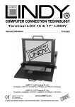
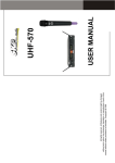
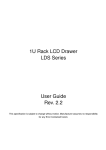
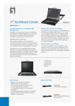
LINDY 15” & 17” LCD Terminals
User Manual
English
LINDY 17” LCD Terminal No’s:
21540(DE), 21541(IT), 21542(FR), 21543(UK), 21544(CH), 21545(US)
LINDY 15” LCD Terminal No’s:
21524(UK), 21526(DE), 21527(IT), 21528(FR), 21529(US), 21519(CH)
Tested to Comply with
FCC Standards
For Commercial Use
www.LINDY.com
© LINDY ELECTRONICS LIMITED & LINDY-ELEKTRONIK GMBH - SECOND EDITION (APRIL 2005)
User manual
15” & 17” LCD Terminals
Supplied Items
The LCD Terminal package consists of:
• 1 x 1U, 19” rack mount console with 17” or 15” LCD screen (according to part
number) and 2 locking keys
• 1 x 19” mounting kit with screws and multiple rear mounting brackets for
mounting to a depth of between 53cm and 100cm
• 1 x 1.8m, 3-in-1 KVM system cable (2 x PS/2 mouse & keyboard, HD15 VGA
at each end)
• 1 x Power cable
• 1 x User manual CD
• 1x Short Manual (printed)
Please check to make sure that the unit has not been damaged during shipping. If
you encounter a problem, please contact your dealer immediately.
Safety Information
• In order to avoid the risk of fire or electric shock, DO NOT expose this
device to liquid or a high humidity environment
• Operate the LCD only at temperatures between +5°C and +40°C
• No user serviceable parts. Refer servicing to qualified personnel
• Carefully read all notes and instructions before using this product
• This device should be securely mounted in a 19” rack enclosure
• Do not use liquid cleaning products or products containing abrasives.
Clean only with a soft damp cloth
• Ensure there is sufficient ventilation to prevent overheating
• Never obstruct or block the ventilation slots or other openings, and do
not position the device in any location where there is insufficient
ventilation
• Use the correct 19” mounting brackets as detailed in this manual!
2
User manual
15” & 17” LCD Terminals
Features
• The LINDY LCD Terminal is designed for use in standard 60cm to 120cm
depth, 19” cabinets. It requires a mounting depth of at least 50cm and a
distance between front and rear 19” rails of at least 43cm.
• The complete drawer can be fully slid in and out of the rack.
• It also offers the option to pull out the LCD tray only and flip it up so that the
screen can be viewed while the keyboard is hidden, and the cabinet doors
are closed and locked.
• 15” 1024 x 768 Active Matrix TFT LCD Screen with support for VGA, SVGA
and XGA OR
• 17” 1280 x 1024 Active Matrix TFT LCD Screen with support for VGA,
SVGA, XGA and SXGA. Also supports SUN resolution of 1152x900
• Built-in 5 language OSD for display adjustment
• Backlight lifetime of 50,000 hours
• PS/2 touch pad
• PS/2 keyboard and separate numeric keypad
• 100-240V AC wide range power supply
• Dimensions: 450/485 x 460 x44mm (WxDxH)
• Weight approx. 15kg, 17kg with packaging
• Environmental Specification – For indoor use only :
o Temperature: 5 ~ 40° C (Operating) 1~50° C (Storage)
o Relative Humidity: 10~90%, Non-Condensing
KVM LCD Terminal Installation and Use
Installing the drawer into a 19” cabinet
Important note: Because the complete
drawer provides the option to slide the
LCD screen out of the rack, allowing it to
be flipped up, you have to make sure that
the rear brackets:
1) can be slid over a distance up to 14cm
2) do not come apart from each other
when slid out 14cm
Distance between
19“ rails
Please measure the distance between front and rear 19” rails of your cabinet and
select the appropriate rear brackets.
3
User manual
15” & 17” LCD Terminals
Depending on the distance between the front and rear 19” mounting rails, the
following brackets should be used:
Between 43cm and 58cm, use rear single
slider brackets.
Between 52cm and 86cm: use short rear L-brackets plus
support brackets
Between 68cm and 83.5cm, use long rear
L-brackets plus support brackets
Note: if you require extended rear L- rackets for longer distances between the
front and rear 19” rails (not cabinet depth!), please contact LINDY support.
Installing the short rear brackets
Please install the brackets and
distance washers as per the
picture to the right. Secure the
washers firmly using the supplied
screws. The sliding distance of the
rear 19” brackets must be the
same as the sliding distance of the
front brackets, when mounted.
4
User manual
15” & 17” LCD Terminals
Installing the long rear brackets
Please select the appropriate brackets according to the distance between your 19”
rails (see Important note on page 3) and install them as per the pictures.
C
You will need the front support
brackets (A), outer slider brackets (B),
inner slider bracket (C).....
B
A
....and either the short or long Lbracket (DS and DL).
DS
DL
First, position the front support bracket
(A) with the outer and inner slider
brackets (B, C) to the back of the
drawer as shown in the picture to the
right.
Select the long or short L-brackets (DS or DL) to fit your cabinet’s 19” rail
distance. Make sure they can slide by an additional 14cm without falling off. Insert
the appropriate L-bracket (DS or DL) into the inner slider bracket (C) and fix it with
the central screw, ensuring the brackets cannot fall off each other when slid. Next,
adjust the inner (C) to the outer (B) slider bracket using one central screw in the
appropriate position. Make sure it can slide over the necessary distance of 14cm.
Central Screws to fix brackets
Long Rear brackets with shortest L-bracket installed
Long Rear brackets with long L-bracket installed and pulled out
5
User manual
15” & 17” LCD Terminals
Mounting the drawer into the cabinet
Fix the front 19” brackets of the drawer
onto the front side of your 19” cabinet. Fix
the screws only to the slider bracket - not
to both brackets!
To slide the complete
drawer out of the 19” rack,
unscrew the two
thumbscrews on the front
of the 19” bracket. This
allows the LCD panel to be
flipped up.
LCD ON/OFF SWITCH
Fix the screws on the back of the drawer onto the rear side of your 19” Cabinet.
Please note: You can hide the handle of the keyboard drawer inside the drawer.
6
User manual
15” & 17” LCD Terminals
Cable connections
1. Ensure the computer or KVM switch you are connecting to is switched
OFF!
2. Use the included ‘3-in-1 2 x PS/2 + 1 x VGA’ cable to connect to the
console ports of your computer or KVM switch
3. Connect the power cable to the mains and to the back of the KVM LCD
Terminal
4. Switch ON the power to the KVM LCD Terminal
5. Switch ON the power to the connected PC or KVM switch
LCD DISPLAY
For adjustment and configuration of the LCD please follow the LCD on screen
menu and select the appropriate language. Please note that an LCD display
requires a frame rate of around 60Hz only! Therefore please adjust the graphics
signal of all attached computers to a maximum of
• 1024x768 @ 60Hz if you are using the drawer with 15” LCD display or
• 1280x1024 @ 60Hz if you are using the drawer with 17” LCD display.
If any graphics card is set to a frame rate of above 72Hz the LCD may not show a
picture – this is not a fault of the LCD but a general feature of any LCD display. In
such cases connect a standard monitor to the computer and set the graphics card
to the correct resolution and frame rate as detailed above!
The 17” LCD display also supports SUN® resolution of 1152x900.
The LCD Drawer features a front power switch to switch off the LCD display. It
can be used to switch off the LCD when the screen is flipped up in front of the
cabinet. When the screen is flipped down (to slide the complete drawer into the
cabinet) the LCD is switched off automatically.
7
Radio Frequency Energy Certifications
Shielded cables must be used with this equipment to maintain compliance with radio frequency
energy emission regulations and ensure a suitably high level of immunity to electromagnetic
disturbances.
FCC Compliance Statement (United States)
This equipment generates, uses and can radiate
radio frequency energy and if not installed and used
properly, that is, in strict accordance with the
manufacturer’s instructions, may cause interference
to radio communication. It has been tested and
found to comply with the limits for a class A
computing device in accordance with the
specifications in Part 15 of FCC rules, which are
designed to provide reasonable protection against
such interference when the equipment is operated in
a commercial environment. Operation of this
equipment in a residential area may cause
interference, in which case the user at his own
expense will be required to take whatever measures
may be necessary to correct the interference. If this
equipment causes interference, what can be
determined by turning the equipment on and off, the
user is encouraged to try to correct the interference
by one or more of the following measures:
a) Reorient or relocate the receiving antenna.
b) Increase the separation between the equipment
and receiver.
c) Connect the equipment to an outlet on a circuit
different from that to which the receiver is
connected.
d) Consult the dealer or an experienced radio/TV
technician
FCC WARNING
Changes or modifications not expressly
approved by the manufacturer could void the
user’s authority to operate the equipment under
FCC Rules.
Canadian Department of Communications RFI
statement
This equipment does not exceed the class B limits
for radio noise emissions from digital apparatus set
out in the radio interference regulations of the
Canadian Department of Communications.
Le présent appareil numérique n’émet pas de
bruits radioélectriques dépassant les limites
applicables aux appareils numériques de la classe
A prescrites dans le règlement sur le brouillage
radioélectriques publié par le ministère des
Communications du Canada
European EMC Directive 89/336/EEC
CE statement
This equipment complies with the requirement
for CE mentioned in the European Directive
89/336/EC and Standards EN55022 and
EN55024.
© LINDY ELECTRONICS LIMITED & LINDY-ELEKTRONIK GMBH - SECOND EDITION (APRIL 2005)