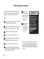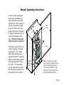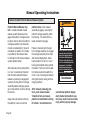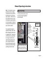
1
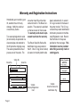
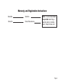
CJKA-**GB')
31937
Under-Vehicle Lift®
Ope
ra
Man tor'
ua s
l
DOT — Public Use Lift
“DOT — Public Use Lift” verifies that this platform lift meets the
“public use lift” requirements of FMVSS No. 403. This lift may be
installed on all vehicles appropriate for the size and weight of the
lift, but must be installed on buses, school buses, and multipurpose passenger vehicles other than motor homes with a gross
vehicle weight rating (GVWR) that exceeds 4,536 kg (10,000 lb).
International Corporate Hdqrs: P.O. Box 310 Winamac, IN 46996 USA
(574) 946-6153
FAX: (574) 946-4670
1-800-THE LIFT ®
www.braunlift.com
TM
TM
34407
October 2007
®
®
Read manual
before operating
lift. Failure to do
so may result in
serious bodily
injury and/or
property damage.
Keep manual in
lift storage pouch.
Braun UVL Series
Operator's Manual
Public Use Wheelchair Lifts
"Providing Access to the World"
WARNING
Operator's Manual
Operator's Manual for:
Congratulations
We at The Braun Corporation wish to express our fullest appreciation
on your new purchase. With you in mind, our skilled craftsmen have designed
and assembled the finest lift available.
This manual includes safety precautions, lift operating instructions, manual operating instructions, and instructions for maintenance and lubrication
procedures.
Your lift is built for dependability, and will bring you years of pleasure
and independence, as long as maintenance is performed regularly and the lift
is operated by an instructed person.
Sincerely,
THE BRAUN CORPORATION
Ralph W. Braun
Chief Executive Officer
Contents
Warranty/Registration Instructions .................. 2, 3
Handrail Operating Instructions ............................... 21
Lift Terminology
Lift Passengers
Lift Terminology Illustration ........................................ 4
Passenger Orientation (Boarding Direction) ..... 22
Introduction ................................................................ 5
Standees ........................................................... 22
Direction .................................................................... 5
Yellow Boundaries ...................................... 22, 23
Lift Components .................................................... 6, 7
Vehicle (Floor Level) Loading and
Vehicle and Lift Interlocks ......................................... 7
Unloading .................................................... 23, 24
Lift Actions and Functions .......................................... 8
Wheelchair-Equipped Occupant Seat Belts ..... 24, 25
Lift Operation Safety
Operation Procedure Review ................................. 25
Safety Symbols ......................................................... 9
Preventive Maintenance ......................................... 26
Lift Operation Safety Precautions ...................... 10-14
Lift Operating Instructions ............................. 27-29
Operation Notes and Details
NHTSA Operations Checklist .............................. 30
Introduction/Lift Access Doors and Interlocks ......... 15
Manual Operating Instructions ....................... 31-35
General Safety ......................................................... 16
Decals and Antiskid ........................................ 36-39
Control Switches ..................................................... 16
Maintenance and Lubrication ......................... 40-48
Lift Features
Inner Roll Stop ............................................ 17, 18
Outer Barrier ............................................... 18, 19
Barrier, Handrail and Belt Manual Operation ........... 20
Page 1
Warranty and Registration Instructions
Immediately upon receiving your
lift, examine the unit for any
damage. Notify the carrier at
once with any claims.
Two warranty/registration cards
(shown below) are protected in a
clear envelope and attached to
the lift protective shipping wrap.
The sales representative must
process one of the cards. The
consumer must fill out the other
card and mail it to The Braun Corporation. The warranty is provided
on the back cover of this manual.
The warranty cards must be processed to activate the warranty.
Two Braun Serial No./Series No.
identification tags are posted on
the lift. One I.D. tag (shown below)
is located on the left platform side
plate (outboard end). A second
I.D. tag is located on the base of
the pump module. This I.D. tag
contains the product identification
information provided on the Warranty/Registration card. Record
the information in the space
provided on the next page. This
information must be provided
when filing a warranty claim or
ordering parts.
Series No.
Model No.
The Braun Corporation
1-800-THE-LIFT TM
BRAUNLIFT.COM TM
Serial No.
DOT Private Use Lift MODEL#
OWNER'S WARRANTY REGISTRATION
NUVL855RM24
NUVL855RM24
Max. Lifting Capacity - 700Lbs.
01-00025
SERIAL NUMBER
01-00025
PURCHASED FROM
OWNER
DATE INSTALLED
MFG DATE
NAME
07/09/2007
ADDRESS
CITY
TELEPHONE
STATE
ZIP
TO VALIDATE WARRANTY
REGISTRATION CARDS MUST BE RETURNED TO THE BRAUN CORPORATION.
Page 2
Sample
Warranty/Registration
Card
Sample
Serial No./Series No.
Identification Tag
Warranty and Registration Instructions
Model No.
Serial No.
Series No.
Date of Manufacture
Note: This information must
be provided when filing a
warranty claim or ordering
parts. Keep for future use.
Page 3
Hydraulic
Cylinders
Lift Terminology
Illustration
Li
ft
H
ou
si
ng
Platform Cable-activated
Manual Release System
Lift Mounting
Bracket
Clamps(6)
WARN
ING
Push
manu T-hand
and ally le
lock out movein fully
to
Failurbefore
engagplatfo and
resulte to drivine rm
deplo in lock gplatfo in
uninteplatfovehiclrm
platfoyment
resultrm . nded rm e.
may
and/orin deploUninte platfo
seriouymentnded rm
prope
s
may
rty bodily
damag injury
Do
not
e.
remo
ve!
Hand-held Attendants
Control Box
81823
Ca
rria
ge
Inner
Roll Stop
Rolling
Horizontal Arms
Torque
Tube
Outer Barrier
Actuator
JK
A
Right
Outboard
P
Left
la
tfo
rm
Inboard
Lifting
Arms
Manual Fold Shield
Handrails with Belt
Page 4
Two-Stage
Outer Barrier
Lift Terminology
Introduction:
Braun NUVL Series lifts are
ADA compliant and comply
fully with National Highway
Traffic Safety Administration
(NHTSA) specifications. The
NUVL855RM24 is commercial
oriented (intended for operation
by an attendant).
Public Use NUVL lift models
provide fully automatic operation of deploy (extend), up,
down and stow (retract) lift
functions. The NUVL855RM24
can be interfaced for fully automatic operation of the power
door system. Manual operating
procedures are required for the
shield handrails and interlocking belt.
Refer to the Lift Terminology
Illustration for identification of
lift components.
Basic lift operation procedures
are identical for all NUVL Series lift models. The operating
instructions contained in this
manual address the lift control
switches and the corresponding lift functions. Operating
procedures for the shield
handrails and interlocking belt
are provided. Instructions are
provided for manual operation
of the lift in event of power or
equipment failure.
Terminology: Become familiar
with the terminology that will be
used throughout this manual.
Become familiar with the identification of lift components and
their functions. Contact your lift
sales representative or call The
Braun Corporation at 1-800THE LIFT® if any of this information is not fully understood.
Direction: The terms "left,"
"right," "inboard," and "outboard"
will be used throughout this
manual to indicate direction (as
viewed from outside the vehicle
looking directly at the lift). Refer
to the Lift Terminology Illustration for clarification of direction
terms.
Page 5
Lift Terminology
Lift Components
Refer to the Lift Terminology Illustration on page 4.
Pump Module: The remote
mounted pump module consists
of the main hydraulic pump, the
manual hand pump, the logic
control board and other electrical
components that power the lift
electric/hydraulic systems.
Hand-held Pendant Control: The hand-held pendant is
equipped with four push button
switches, (DOOR, STOW, DOWN
and UP). The momentary switches activate the automatic lift
functions. Simply press the switch
labled for the intended function.
The lift function labels illuminate
to identify the function(s). Details
Page 6
regarding the control switches
and their functions are provided in
the Lift Operation section.
Lift Housing: The lift housing
is the metal structure (casing)
mounted under the vehicle which
contains and protects the platform
carriage assembly. The housing contains all lift components
except the power (pump) module
when the lift is in the stowed position.
Platform Carriage Assembly:
The platform carriage assembly
includes the platform assembly,
the lifting arms, the rolling horizontal arms that carry the platform assembly in and out of the
housing and the electrical/hydraulic drive components that power
the lift.
Platform Assembly: The lift
platform assembly consists of the
flat aluminum plate upon which
the wheelchair is positioned, the
outer barriers, the inner roll stop
and shield handrails.
Outer Barrier: The two-stage
outer barrier system consists of a
spring-loaded tall barrier and an
electric actuator-driven short barrier. The two-stage outer barrier
provides a ramp for wheelchair
loading and unloading at ground
level. Photos and further details
are provided in the Operation
Notes and Details section (pages
18-21).
Inner Roll Stop: The NUVL855RM24 is equipped with an
automatic inner roll stop that also
serves as the bridge plate. The
Lift Terminology
inner roll stop bridges the gap
between the lift platform and the
vehicle floor. The inner roll stop
automatically rotates from the
horizontal position to the vertical position as the lift lowers and
raises. Further details regarding
the automatic mechanical inner
roll stop are provided on pages
17 and 18.
Platform Cable-activated Manual Release System: A cableactivated manual release system
releases the platform carriage
assembly drive chain to allow the
platform carriage assembly to be
manually moved out (extended)
or moved in (retracted), should it
be necessary. Complete details
and operating procedures are
provided on page 32.
Vehicle and Lift Interlocks
Braun Corporation NUVL Series
lifts comply fully with all NHTSA
vehicle and lift interlock specifications. Vehicle movement is
prohibited unless the lift is fully
stowed and the lift will not function unless the vehicle is parked
and secured.
cannot be stowed if occupied.
The lift platform cannot be raised
or lowered unless the roll stop
and outer barriers are deployed
(up).
The NUVL855RM24 features
a visible and audible threshold
warning system that will activate
if the threshold area is occupied
when the platform is one inch or
more below floor level.
The inner roll stop and outer barriers sense weight to prohibit lift
operation. The lift will not function
if the inner roll stop or outer barriers are occupied. The lift platform
Page 7
Lift Terminology
Lift Actions and Functions:
Deploy (Extend): Lift deployment is the action of the lift platform carriage assembly extending (moving outward) from the
housing and lowering to ground
level when the DOWN switch is
activated or raising to floor level
when the UP switch is activated.
Stow (Retract): Stow is the
action of the lift platform and carriage assembly retracting (moving
inward) into the lift housing. During the stow function, the platform
will automatically raise or lower to
stow level before retracting into
the housing.
DOWN - Platform Lower: Down
is the action of the platform lowering from stow or floor level posi-
Page 8
tion to fully-lowered (ground level)
position when the DOWN switch
is pressed.
DOWN - Outer Barrier Unfold (Down) - When the platform reaches the fully-lowered
(ground) position and the DOWN
switch is continued to be pressed,
the outer barriers rotate downward from vertical position to
ramp position.
UP - Outer Barrier Fold (Raise):
From ground level, the UP function automatically raises (rotates)
the actuator activated outer barriers to the upright (vertical) position before the platform raises.
UP - Platform Raise: Up is the
action of the platform raising from
stow level or ground level to floor
level (fully-raised) position when
the UP switch is pressed. When
the lift is fully lowered, pressing the UP switch first raises the
outer barrier.
Note: The lift platform will not
raise if the outer barriers are not
in the upright (vertical) position.
This is a built in safety feature.
Stow Level: Stow level is the
height that the platform and carriage assembly moves in and
moves out of the lift housing.
Floor Level: Floor level is the
height that the platfom and carriage assembly raises to in order
for the wheelchair passenger to
enter and exit the vehicle (fully
raised position).
Lift Operation Safety
Safety Symbols
SAFETY FIRST!
Know That....
All information contained
in this manual and
supplements (if included), is provided for your safety. Familiarity
with proper operation instructions
as well as proper maintenance
procedures are necessary to ensure safe, troublefree operation.
Safety precautions are provided
to identify potentially hazardous
situations and provide instruction
on how to avoid them.
A
D
B
WARNING
This symbol indicates
important safety
information regarding
a potentially hazardous situation that
could result in serious
bodily injury and/or
property damage.
C
CAUTION
This symbol indicates
important information
regarding how to
avoid a hazardous
situation that could
result in minor personal injury or property damage.
Note: Additional information provided to help clarify or detail a specific subject.
These symbols will appear throughout this manual as well as on the labels posted on your lift. Recognize
the seriousness of this information.
Page 9
Lift Operation Safety
Lift Operation Safety Precautions
WARNING
If the lift operating
instructions, manual
operating instructions
and/or lift operation
safety precautions are
not fully understood,
contact The Braun
Corporation immediately. Failure to do so
may result in serious
bodily injury and/or
property damage.
WARNING
Read manual and supplement(s) before operating lift. Read
and become familiar with all safety precautions, lift operation
notes and details, operating instructions and manual operating instructions before operating the lift. Note: Wheelchair
passengers and all transit agency personnel (drivers and
wheelchair lift attendants) must read and become familiar
with the contents of this manual and supplement(s) before
operation.
WARNING
Load and unload on level surface only.
WARNING
Engage vehicle parking brake before operating lift.
WARNING
Provide adequate clearance outside the vehicle to accommodate the lift before opening lift door(s) or operating lift.
WARNING Inspect lift before operation. Do not operate lift if you suspect lift damage, wear or any
abnormal condition.
WARNING Keep operator and bystanders clear of area in which the lift operates.
Page 10
Lift Operation Safety
WARNING
Whenever a wheelchair passenger (or standee) is on the platform, the:
• Handrail belt must be latched.
• Passenger must be positioned in the center of the platform.
• Wheelchair brakes must be locked
• Inner roll stop and outer barriers must be up (vertical)
• Passenger should grip both handrails (if able).
WARNING
Load and unload clear of vehicular traffic.
WARNING
Do not overload or abuse. The load rating applies to both the raising and lowering functions - continuous lifting capacity is 700 lbs.
WARNING
Discontinue lift use immediately if any lift or vehicle interlock does not operate properly.
WARNING
Do not operate or board the lift if you or your lift operator are intoxicated.
WARNING
Do not raise front wheelchair wheels (pull wheelie) when loading (boarding) the platform.
WARNING
Open lift door(s) fully and secure before operating lift.
WARNING
Position and secure (buckle, engage, fasten, etc.) the wheelchair-equipped occupant
seat belt (torso restraint) before loading onto the wheelchair lift platform.
WARNING
Fold outer barrier and handrails down to platform before stowing lift.
Page 11
Lift Operation Safety
Lift Operation Safety Precautions (continued)
WARNING
If the lift operating
instructions, manual
operating instructions
and/or lift operation
safety precautions are
not fully understood,
contact The Braun
Corporation immediately. Failure to do so
may result in serious
bodily injury and/or
property damage.
WARNING Lift attendants must ensure that lift occupants keep hands,
arms and all other body parts within the lift occupant area
and clear of moving parts.
WARNING Platform must be positioned at floor level (bridging position)
when loading or unloading in and out of vehicle.
WARNING Do not use platform inner roll stop or outer barriers as a
brake. Stop and brake wheelchair when loading onto the
platform (manually stop and brake manual wheelchairs
— stop powered wheelchairs with the wheelchair controls).
WARNING Turn powered (electric) wheelchairs off when on lift platform.
WARNING
Press the DOWN switch until the entire platform rests on
ground level (lowered fully) and the outer barriers are fully
unfolded (ramp position) before loading or unloading a passenger at ground level.
WARNING Both outer barriers must be fully unfolded (ramp position) until front and rear wheelchair
wheels cross the barriers when loading or unloading at ground level.
Page 12
Lift Operation Safety
WARNING
Accidental activation of control switch(es) may cause unintended operation(s).
WARNING
After manually releasing platform, stow platform and push manual release T-handle in fully
and move platform in and out to engage platform lock before driving vehicle. Failure to
lock platform may result in unintended platform deployment.
WARNING
Insert manual relaese T-handle fully before manually lowering or raising platform and
manually move platform in and out to engage platform lock.
WARNING
Maintenance and lubrication procedures must be performed as specified in this manual by
authorized (certified) service personnel.
WARNING
Replace missing, worn or illegible decals.
WARNING
Keep owner’s (operator's) manual in lift vehicle at all times.
WARNING
Never modify (alter) a Braun Corporation lift.
WARNING
Do not use accessory devices not authorized by The Braun Corporation.
WARNING
Do not remove any guards or covers.
Page 13
Lift Operation Safety
Lift Operation Safety Precautions (continued)
WARNING
If the lift operating
instructions, manual
operating instructions
and/or lift operation
safety precautions are
not fully understood,
contact The Braun
Corporation immediately. Failure to do so
may result in serious
bodily injury and/or
property damage.
Page 14
WARNING
Keep clear of any hydraulic leak.
WARNING
Failure to follow these safety precautions may result in
serious bodily injury and/or property damage.
Operation Notes and Details
WARNING
Read and become
familiar with all lift
operation safety
precautions, operation notes and details,
operating instructions
and manual operating instructions prior
to operating the lift.
If this information is
not fully understood,
contact The Braun
Corporation immediately. Failure to do so
may result in serious
bodily injury and/or
property damage.
NUVL “Public Use” lift models are
specifically designed to be operated by an attendant. The Lift
Operating Instructions contained
in this manual and appearing on
the lift operating instructions decal
provide instructions for operation
of the lift only. Read and become
familiar with all lift operation safety
precautions, operation notes and
details, operating instructions and
manual operating instructions
before attempting lift operation
procedures.
procedures to operate them vary.
Instructions for operation of vehicle interlocks and door securement systems are not addressed
in this manual or on lift-posted operating instructions decals due to
the variety of procedures required
for operating them. Braun Corporation NUVL Series lifts comply
fully with all NHTSA vehicle and lift
interlock specifications (detailed
on pages 18-23). Infringement
of any lift interlock will prohibit lift
operation.
Lift Access Doors and Interlocks: Attendants must become
familiar with the vehicle lift access
door system and vehicle interlock
system(s). Transit vehicles and
lift access door configurations
vary. Door securement devices
(latches, hooks, cables, etc.) and
It is the responsibility of the lift
operator (attendant) to properly
open, secure and close the vehicle
lift door(s), to activate the vehicle
interlock(s), to load and unload the
wheelchair passenger (or standee)
on and off the lift platform, and to
properly activate all lift functions.
Page 15
Operation Notes and Details
General Safety: The lift operator
(attendant) and bystanders must
keep clear of the area in which
the lift operates and clear of all
moving parts. Lift attendants
must ensure that lift occupants
(passengers) keep hands, arms
and all other body parts within
the lift occupant area and clear of
moving parts.
Control Switches
Lift Power ON/OFF Switch:
This switch must be in the ON
position in order to activate the
lift. The green Power Indicator
Light illuminates to signal power
to the lift.
tions. Simply press the switch
labeled for the intended function. When there is power to
the lift, the lift function labels
illuminate to identify the functions.
DOOR
STOW
DOWN
UP
Hand-held Pendant Control:
The hand-held attendent's
pendant control is equipped
with four push button switches
(DOOR, STOW, DOWN and
UP). The momentary switches
activate the automatic lift funcHand-held Pendant
Page 16
Operation Notes and Details
Lift Features
Inner Roll Stop: The NUVL855RM24 is equipped with an
automatic inner roll stop that also
serves as a bridge plate. The
spring loaded inner roll stop automatically deploys (rotates) to the
vertical position when the platform
extends from the stow position.
When the UP switch is pressed
and the platform raises to floor
level, this mechanical roll stop is
automatically rotated to the bridging (horizontal) position to provide
a bridge plate between the plat-
form and the vehicle floor. The
inner roll stop must rest solidly
on the vehicle floor (minimum
1½" overlap). The roll stop automatically deploys (rotates) to the
vertical (roll stop) position as the
platform lowers (DOWN switch is
pressed).
Fully Deployed Fully Unfolded
(vertical)
(horizontal)
Inner
Inner Roll Stop
Roll Stop
(bridging position)
Inner Roll Stop
The inner roll stop must rest
solidly on the vehicle floor
(minimum 1½" overlap).
Page 17
Operation Notes and Details
WARNING
Discontinue lift use
immediately if any
lift component does
not operate properly. Failure to do so
may result in serious
bodily injury and/or
property damage.
The inner roll stop automatically
folds down to the platform surface (horizontal) during the stow
function (as platform retracts).
Interlock Feature: The inner roll
stop senses weight (pressure) to
prohibit lift operation. The lift will
not function if the inner roll stop
is occupied.
Page 18
Discontinue lift operation immediately if the inner roll stop
does not operate properly.
Outer Barrier: The two-stage
outer barrier provides a ramp for
wheelchair loading and unloading at ground level (see photos
on following page). When the
platform lowers fully to ground
level, the electric actuator unfolds
(rotates) the barriers to the ramp
position (fully unfolded).
The tall outer barrier is spring
loaded but driven by the electric
actuator-powered short outer barrier to rotate from the ramp (horizontal) position to the deployed
(vertical) position.
Note: The tall outer barrier must
be manually raised and lowered
from the platform surface when
extending and retracting the
platform. Details are provided on
pages 20 and 21.
Although the outer barriers are
lift-powered, the activation of the
barriers are controlled by the lift
operator (attendant). Pressing
the DOWN switch unfolds the
barriers. The actuator-powered
two-stage outer barriers fold (rotate) to the vertical position when
the UP swiitch is pressed.
Note: The lift platform will not
raise if the outer barriers are not
fully deployed (up).
Interlock Features: The outer
barriers sense weight to prohibit lift operation. The lift will not
function if the outer barriers are
Operation Notes and Details
occupied. Lift platform movement shall be interrupted unless
the outer barrier is fully deployed
(up).
The attendant must view the
platform as it lowers to be certain
the entire platform reaches and
rests safely on the ground. Stop
pressing the DOWN switch if any
portion of the platform is obstructed while descending or the entire
platform does not reach ground
level for any reason (contact
with an obstruction, mechanical
failure, exceeding the lift "floor-toground" capacity, etc.). After the
platform is fully lowered, the attendant should continue to press
the DOWN switch to unfold the
outer barrier fully (ramp poition).
Note: The barrier must be fully
unfolded until the entire wheelchair (or standee) has crosed the
barrier when loading or unloading
at ground level. Discontinue lift
operation immediately if the
outer barriers do not operate
properly.
Outer Barrier
Fully-Deployed Fully-Unfolded
Outer Barriers
Barriers
(Up-vertical)
(Ramp position)
Page 19
Operation Notes and Details
Barrier, Handrail and Belt Manual Operation
The folding handrails and tall outer barrier are manually operated.
The spring-loaded outer barrier
(tall barrier) and the handrails rest
on the platform when the lift is not
in use. The outer barrier must be
raised to the vertical position and
the handrails must be lifted to the
vertical position whenever a passenger is on the platform.
The tall outer barrier and the
handrails must be folded down
to the platform (horizontal) position before stowing the lift. The
handrails fold down onto the
outer barrier to secure the barrier
in the horizontal position. Each
handrail is secured with a latch
handle.
Page 20
The latch handles must be lifted
before the handrails can be
folded or unfolded and must be
lowered after folding or unfolding the handrails.
Interlocking Handrail Belt: The
NUVL855RM24 is equipped with
an interlocking handrail belt.
Once the lift platform has extended fully from the stowed position,
the belt must be latched in order
to raise or lower the platform.
During the Stow function, the
belt must be unfastened after the
platform raises or lowers to stow
level and stops. With the belt
unlatched, pressing the STOW
switch then retracts the platform
fully.
WARNING
Before stowing lift:
• Lower outer barrier
down to platform.
• Lower handrails down
to platform.
• Lower latch handles
down to platform.
Failure to follow these
precautions may result
in serious bodily injury
and/or property damage.
Refer to the procedures on the
following page for operation of
the barrier and handrails.
Operation Notes and Details
Handrail Operating Instructions
1. Fold tall (yellow) outer barrier
down.
2. a. Lift latch handle.
b. Deploy / Stow handrail.
c. Lower latch handle.
3. a. Lift latch handle.
b. Deploy / Stow handrail.
c. Lower latch handle.
a.
JK
Latch
Handle
Detail
JK
A
b.A
c.
b.
Note: Order of procedures
shown is for stowing lift. To
deploy handrails and barrier
after extending the platform,
reverse order of procedures.
c.
a.
JK
A
Latch
Handle
Detail
Page 21
Operation Notes and Details
Lift Passengers
If you are an attendant operating
the lift, it is your responsibility to
perform safe loading and unloading procedures. Wheelchair lift
attendants should be instructed
on any special needs and/or procedures required for safe transport of wheelchair passengers.
The lift operator and bystanders
must keep clear of the area in
which the lift operates. Observe
your passenger at all times during
lift operation.
Do not attempt to load or unload
a passenger in a wheelchair or
other apparatus that does not fit
on the platform area. Do not exceed the 700 pound load capacity
Page 22
of the lift. The lift attendant should
not ride on the platform with the
passenger.
Passenger Orientation (Boarding Direction): Braun "Public
Use" NUVL Series wheelchair lifts
accommodate both inboard and
outboard facing wheelchair passengers or standees. Inboard facing of wheelchair lift passengers is
not prohibited, but outboard facing of passengers is recommended by The Braun Corporation.
Braun "Public Use" NUVL Series lifts permit both inboard and
outboard facing of wheelchair and
mobility aid users and accommodate persons using walkers,
crutches, canes or braces or who
otherwise have difficulty using
steps.
Standees: Lift Operating Instructions apply to wheelchair passengers and standees. Standees
should stand in the center of the
platform (fully inside the yellow
boundaries) and grip both handrails (if able) when on platform.
Yellow Boundaries: The passenger must be positioned in the
center of the platform to prevent side-to-side load imbalance.
The lift attendant (operator)
should not ride on the platform
with the passenger.
Yellow platform loading boundaries are identified in the following
manner. The yellow powdercoated inner roll stop and tall
outer barrier identify the inboard
and outboard ends of the platform.
Operation Notes and Details
Platform side plates and handrail
bases are powder coated yellow
also.
parts within the lift occupant area
and clear of all moving parts.
Threshold Warning: The vehicle
-mounted black threshold warning
mats identify the platform threshold area. Interlock: A visible and
audible threshold warning system
will activate if the threshold area
is occupied when the platform
is one inch or more below floor
level.
Vehicle (Floor Level) Loading
and Unloading: The platform
must be fully raised (at floor level)
and the inner roll stop must be
properly positioned when loading
or unloading passengers in or out
of the vehicle. It is the responsibility of the lift attendant to ensure the platform and the inner
roll stop are properly positioned
at floor level when loading and
unloading passengers.
The attendant must always be
certain the wheelchair passenger
or standee is properly positioned
on the platform (fully inside yellow boundaries) and the wheelchair brakes are locked when a
passenger is on the lift platform.
The lift passenger must keep
hands, arms and all other body
The wheelchair brakes must be
locked, the outer barriers must be
in the fully-deployed (up) position
and the handrail belt must be
latched whenever a passenger
is on the platform.
WARNING
Whenever a
passenger is on the
platform, the:
• Handrail belt must
be latched
• Passenger must be
positioned in the
center of the
platform.
• Wheelchair brakes
must be locked
• Inner roll stop and
outer barriers must
be UP
Failure to follow these
rules may result in
serious bodily injury
and/or property
damage.
Page 23
Operation Notes and Details
Lift Passengers
Do not use the outer barriers as a brake. Stop and
brake the wheelchair when
fully loaded on the platform. Manually stop and
brake manual wheelchairs.
Stop powered wheelchairs
WARNING
Discontinue lift use
immediately if any
lift component does
not operate properly. Failure to do so
may result in serious
bodily injury and/or
property damage.
Page 24
Wheelchair-Equipped
Occupant Seat Belts
with the wheelchair controls.
Turn powered (electric) wheelchairs off when on the platform.
If the outer barriers, inner roll
stop, handrails, handrail belt
or any other lift component
does not operate as outlined in
this manual, discontinue lift
use immediately and contact
The Braun Corporation sales
representative in your area or
call The Braun Corporation at
1-800-THE LIFT®. One of our
national Product Support representatives will direct you to an
authorized service technician
who will inspect your lift.
The Braun Corporation recommends wheelchair passengers
position and buckle their wheelchair-equipped seat belt (torso
restraint) before loading onto a
wheelchair lift.
Different types of disabilities
require different types of wheelchairs and different types of
wheelchair-equipped occupant
restraint belt systems (torso
restraints). It is the responsibility of the wheelchair passenger
to have his or her wheelchair
equipped with an occupant
restraint (seat belt) under the
direction of their health care
professional.
Operation Notes and Details
Operation Procedure Review
Wheelchair lift attendants
should be instructed on any
special needs and/or procedures required for safe transport of wheelchair passengers.
WARNING
Position and secure
(buckle, engage,
fasten, etc.) the
wheelchair-equipped
occupant seat belt
before loading onto
the wheelchair lift
platform. Failure to
do so may result in
serious bodily injury
and/or property
damage.
The Braun Corporation recommends that transit agency supervisors and wheelchair lift attendants review the safety precautions and operation procedures
appearing in this manual and on
lift operating instruction decals
with your wheelchair lift sales
representative (dealer), before
attempting lift operation.
Any questions or concerns can
be answered by the sales representative at that time. Operate
the lift through all functions with
your sales representative on
hand to ensure the proper use
and operation of the wheelchair
lift is understood.
Transit agency supervisors
should train and educate their
lift attendants on the proper use
and operation of the wheelchair
lift if it is not possible for the
attendants to review the safety
precautions and operation procedures with the wheelchair lift
sales representative.
The lift operator's manual must
be stored in the lift vehicle at
all times.
Page 25
Operation Notes and Details
Preventive Maintenance:
Maintenance is necessary to
ensure safe and troublefree
lift operation. General preventive lift maintenance consisting
of careful inspections of the
lift system and cleaning the lift
should be a part of your transit
agency's daily lift service program. Simple inspections can
detect potential lift operational
problems.
Keeping the lift platform and
housing area clean is one of
the most effective preventive
maintenance practices to exercise. Dirt, mud, snow, ice and
other debris entering the housing could result in potential lift
problems.
Page 26
WARNING
Regular preventive maintenance
will reduce potential lift operation
downtime and increase the service life of the lift, as well as possibly detecting potential hazards.
Exposure to harsh weather elements, environmental conditions,
or heavy usage may require
more frequent maintenance and
lubrication procedures.
Preventive maintenance visual inspections do not take the
place of the procedures specified
in the Maintenance and Lubrication Schedule provided on pages
40-48 of this manual. Refer to
the Maintenance and Lubrication
section for further details.
Maintenance and
lubrication procedures
must be performed
by authorized service
personnel as specified
in this manual. Failure
to do so may result in
serious bodily injury
and/or property
damage.
Lift Operating Instructions
WARNING
Whenever a
passenger is on the
platform, the:
• Handrail belt must
be latched
• Passenger must be
positioned in the
center of the
platform.
• Wheelchair brakes
must be locked
• Inner roll stop and
outer barriers must
be UP
Failure to follow these
rules may result in
serious bodily injury
and/or property
damage.
WARNING
Read and become
familiar with all lift
operation safety
precautions, operation notes and details,
operating instructions
and manual operating instructions prior
to operating the lift.
If this information is
not fully understood,
contact The Braun
Corporation immediately. Failure to do so
may result in serious
bodily injury and/or
property damage.
Before lift operation, park the
vehicle on a level surface, away from
vehicular traffic. Place the vehicle
transmission in "Park" and engage
the parking brake.
Instructions and procedures are
applicable for the NUVL855RM24.
Warnings and Lift Operating Instructions decal 34270 provides lift
operating instructions. Replace any
missing, worn or illegible decals.
If your lift does not function as intended or a visual or audible warning
signal is activated, review the NHTSA
Operations Checklist on page 30.
Follow the Manual Operating Instructions on pages 31-35 in the event of
a power or equipment failure.
Page 27
Lift Operating Instructions
OPEN DOOR(S) AND SECURE
TO DEPLOY PLATFORM:
1. Stand clear and press the UP switch until the
platform extends fully. Release switch.
2. Lift handrail latch handles, deploy (lift) handrails
up to vertical position and lower handrail latch
handles fully.
3. Lift outer barrier to vertical position.
4. Latch handrail belt.
5. Press the UP switch until the platform stops
(raises to floor level) and inner roll stop unfolds to
floor level. Release switch.
TO UNLOAD PASSENGER:
1. Read Note below! Load passenger onto platform and lock wheelchair brakes.
Note: Passenger must be positioned fully inside
yellow boundaries, outer barrier must be UP
and handrail belt must be latched.
2. Press DOWN switch until the entire platform
reaches ground level and the outer barrier unfolds fully (ramp position). Release switch.
3. Unlatch handrail belt, unlock wheelchair brakes
and unload passenger from platform.
Note: Outer barrier must be fully unfolded
(ramp position) until the entire wheelchair (or
standee) has crossed the outer barrier.
Page 28
Lift Operating Instructions
TO LOAD PASSENGER:
1. Read Notes below! Load passenger onto platform, lock wheelchair brakes and latch handrail
belt.
Note: Outer barrier must be fully unfolded
(ramp position) until the entire wheelchair (or
standee) has crossed the outer barrier.
Note: Passenger must be positioned fully inside
yellow boundaries.
2. Press UP switch to fold outer barrier UP fully
(vertical), raise the platform to floor level and unfold inner roll stop to floor level. Release switch.
3. Unlock wheelchair brakes and unload passenger
from platform.
TO STOW PLATFORM:
1. Latch handrail belt.
2. Press STOW switch until platform stops at stow
level. Release switch.
3. Unlatch handrail belt.
4. Fold outer barrier down to platform (horizontal)
position.
5. Lift handrail latch handles, stow (fold) handrails
down to platform (horizontal) position and lower
handrail latch handles fully.
6. Press STOW switch until platform stops (retracts
fully). Release switch.
CLOSE DOOR(S)
Page 29
NHTSA Operations Checklist
The following operations have been verified upon
installation. This operational checklist can be used
at any time to verify the lift is fully functional.
Verified:
Vehicle movement is prevented unless the lift door
is closed, ensuring the lift is stowed.
Lift operation shall be prevented unless the vehicle
is stopped and vehicle movement is prevented.
The platform will not fold/stow if occupied.
Platform movement is prohibited
beyond the position
where the inner roll
stop is fully deployed (up).
Lift platform movement shall be
interrupted unless
the outer barrier is
deployed (up).
WARNING
Discontinue lift use
immediately if any lift
or vehicle interlock
does not operate
properly. Failure to
do so may result in
serious bodily injury
and/or property
damage.
The inner roll stop will not raise if occupied.
Verify platform lighting when lift is deployed and
pendant illumination when lift is powered.
The outer barrier will not raise if occupied.
A visual and audible warning will activate if the
threshold area is occupied when the platform is at
least one inch below floor level.
Page 30
Public use vehicle manufacturers are responsible
for complying with the lift lighting requirements in
Federal Motor Vehicle Safety Standard No. 404,
Platform Lift Installations in Motor Vehicles (49 CFR
571.404).
Manual Operating Instructions
In event of power or equipment
failure, refer to the Manual Operating Instructions to manually
operate the lift. Step-by-step procedures are provided on pages
34 and 35. Refer to the Lift Operating Instructions for all normal
lift operation procedures (such as
loading and unloading passengers). Follow all Lift Operation
Safety Precautions at all times!
Familiarize yourself with the components necessary to manually
operate the lift. The T-handle
release cable releases and engages the lift platform to allow the
platform to be manually extended
and retracted (details on Pages
32 and 33). The manual backup pump (hand pump) is used to
manually lower and raise the extended platform (see Page 33).
Hand
Pump
Valve
T-Handle
Release
Cable
Note: The location of the power
pack and release cable varies from
vehicle to vehicle (depending on
your particular installation). Standard NUVL pump module shown in
Manual Operating Instructions.
Page 31
Manual Operating Instructions
Cable-Activated Platform Manual Release System
Platform Manual Release System: A cable-activated manual
release system releases and engages the platform carriage assembly drive chain to allow the platform
carriage assembly to be manually
moved out (extended) or moved in
(retracted) as needed. A T-handle
is provided on the release cable
for activation of the manual release
system (details follow).
After manually moving the platform
in or out, it is extremely important
that the cable-activated manual
release is positively re-engaged to
secure (lock) the platform carriage
assembly before loading a passenger on the platform or before driving
the vehicle.
Grasp the outer barrier and move
the platform in and out until the
Page 32
WARNING
platform locks (chain release
assembly engages), securing the
platform carriage assembly within
the housing. You will feel the release mechanism engage.
Failure to manually lock the platform carriage assembly (re-engage
the carriage assembly drive chain)
after manual deployment, will allow the platform to roll in or out of
housing unhindered during vehicle
movement. Failure to lock the platform will also allow the platform to
roll in or out of housing unhindered
during hand pump raising and lowering procedures.
After manually releasing platform, push manual release
T-handle in fully and ensure
platform is locked before driving
lift vehicle. Uncontrolled and
Push T-handle in fully and
manually move platform in
and out to engage platform
lock before driving vehicle.
Failure to lock platform may
result in unintended platform
deployment. Unintended
platform deployment may
result in serious bodily injury
and/or property damage.
81823
Do not remove!
unintentional platform deployment (inadvertent platform ejection) may result in serious bodily
injury and/or property damage.
Manual Operating Instructions
The manual hand pump is used
to lower and raise the platform
and outer barrier.
Release Valve
A
Note: Close backup pump
release valve securely before operating electric pump.
Valve
Tightening
Specification:
Once valve
seats (stops),
tighten 15 to 30
inch pounds as
shown.
approximate
1/16” intervals
maximum
30 inch lbs
minimum
15 inch lbs
seats
(stops)
OSE
CL
If you experience power or
equipment failure, refer to the
Manual Operating Instructions
to operate the lift. Instructions
and illustrations are provided
for all steps that differ from
standard lift operation procedures. Manual Instructions
Decal 31409 (posted in pump
module box) provides manual
operating instructions also.
Manual Hand Pump
OPEN
Note: The lift platform must be
pushed back into its carriage
compartment all the way before
reverting back to normal (powered) operation. When the lift is
fully extended manually, it does
not activate the proper switches
for normal operation. Returning
(moving) the lift in fully allows for
proper switch activation.
Release Valve
Page 33
Manual Operating Instructions
Refer to Figures A-C for the Manual Operating Instructions on page 35.
Figure A
Figure C
Figure B
Figure D
Ac
tua
Ha
irp
Co in
tter
tor
AT
F
O
R
M
OPEN
OSE
CL
OSE
CL
VALVE
OPEN
VALVE
t re
mo
ve!
Page 34
818
23
OPEN
O
U
TE
R
Pus
manh Tha
an ually ndle
d
lock out mov in fu
Fa befoto en e platlly an
ilu
ga
resu re tore dr ge form d
de lt in lockivingplatfo in
pl
plat oym unin plat vehi rm
te form cle.
resuform ent. nded
an lt in depl Unint platmay
d/or se oy en fo
propriou men ded rm
ertys bo t may
da dily in
Do
mag ju
no
e. ry
B
A
R
R
IE
R
PL
WA
RN
ING
CLOSE
t
ten
De n
Pi
Manual Operating Instructions
OUT (To Extend Platform):
1. Pull T-Handle (see Figure A).
2. Turn T-Handle to lock platform
in released position.
3. Pull platform out.
4. Turn T-Handle.
5. Push T-Handle in.
6. Turn T-Handle to lock platform
in engaged position.
DOWN (To Lower Platform):
Using hand pump handle, open
hand pump valve (turn counterclockwise). See Figure B. Open
1/2 turn only.
DOWN (Unfold Outer Barrier):
1. Remove hairpin cotter from
detent pin (see Figure D).
2. Remove detent pin.
3. Unfold (rotate) barrier down.
UP (To Fold Outer Barrier):
1. Fold (rotate) barrier up.
2. Insert detent pin.
3. Insert hairpin cotter in detent
pin.
UP (To Raise Platform):
Using hand pump handle:
1. Close hand pump valve (turn
clockwise).
2. Insert handle in pump and
stroke. See Figure C.
IN (To Stow Platform):
1. Raise or lower platform to
stow level (follow UP or
DOWN procedures).
2. Pull T-Handle.
3. Turn T-Handle to lock platform
in released position.
4. Push platform in.
5. Turn T-Handle.
6. Push T-Handle in.
7. Turn T-Handle to lock platform
in engaged position.
Note: Close valve before
operating electric pump.
Page 35
Decals and Antiskid
Decal Placement
WARNING
81819,
12377 and
29440
81823
29059
and
29060
WARN
ING
Push
manual
T-hand
and ly le
lock out movein fully
to
before
Failure
platform
engage
and
result to driving
platform
in
deploym
in lock
vehicle
platform
platform uninten
result ent.
.
ded may
Unintenplatform
and/orin deploy
serious
propert ment ded
may
bodily
y damag
Do
injury
not
e.
remo
ve!
81823
81819
81819
R
GE
DAN
S
PART
ING
R
CLEA
OF
MOV
KEEP
KEEP
OF
GER
DAN
CLEAR
G PARTS
MOVIN
12377
81819
PAR
TS
CLE
AR
OF
MOV
ING
DAN
GER
81819
34430
and
34431
P
The lift is only as safe as
the operator. Replace
any missing, worn or
illegible decals! Part
numbers are provided for
decals. Inspect your lift for
missing, worn or illegible
decals. Call 1-800-THE
LIFT® for replacements.
29058
(not visible)
29064
and
29065
KEE
Replace missing, worn
or illegible decals.
Failure to do so may
result in serious bodily
injury and/or property
damage.
JK
A
WA
RN
ING
• Fold
beforhandr
• Hand
e stowi
ails
be rail
insert deten
ng down
excep
lift.
unfoldt ed
whenin t pins
handr
Failur ing
foldin must
handr
ails
preca e
Befor
g
to
stowi e
in
follow ails. and
utions
seriou
and/o
lift:ng
(Steps
maythese
s bodily
r prope
1-3)
result
rty injury
dama
After
deplo
ge.
ying
lift:
(Reverse
HA
ND
RA
IL
JKA
procedur
es)
1.
Fold
outer
barrie
r down
INS
TR
UC
c.
TIO
.
NS
a.
JKA
c.
a.
c.
b.
c.
a.
JKA
a.
b. Pull
c. Folddetena.
Insert/ Unfold
t pins.
deten
handr
t pins.
ail.
3.
deten
handr a.
t pins.
ail.
81768
Page 36
1-800-THE LIFT™
BRAUNLIFT.COM™
NUVL855R
SERIAL NUMBER
01-00025
DOT Public Use Lift MODEL#
MFG DATE
Max. Lifting Capacity - 750 lbs.
The Braun Corporation
31937 and 27061
(not visible)
09/16/05
33602
e5*72/245*95/54*0102*00
81819
U.S. PATENT 4958979
Note: Clean surfaces as
detailed on page 37 before
posting decals.
b.
a.
b. Pull
c.
c. Folddeten
Insert/ Unfold
t pins.
32240
2.
Decals and Antiskid
Decals
30787
81823
81819
CAUTION
29440
DANGER
WARNING
WARNING
KEEP CLEAR OF MOVING PARTS
12377
Push T-handle in fully and
manually move platform in
and out to engage platform
lock before driving vehicle.
Failure to lock platform may
result in unintended platform
deployment. Unintended
platform deployment may
result in serious bodily injury
and/or property damage.
Improper handling
and/or servicing
procedures may
result in
electrostatic
discharge (ESD)!
ESD may result in
electronic module
damage.
Face outward and lock wheelchair
brakes before operating lift.
29440
THIS WHEELCHAIR LIFT
CONFORMS TO THE CALIFORNIA
CODE OF REGULATIONS
REQUIREMENTS IN EFFECT ON
THE DATE OF MANUFACTURE. 12377
81823
Do not remove!
30787
29064
29065
Lift Out
Full Out
29065
Increase
Out
Travel
29064
27061
Full
Out
29058
29058
Decrease
Out
Travel
81819
34430
Lower
Close Door
Height
Switch
0
34430
34431
Raise
Close Door
Height
Lower
Open Door
Height
29059
Decrease
Stow
Level
Stow
Start
29059
Switch
1
34431
Raise
Open Door
Height
29060
Increase
Stow
Level
Decrease
Floor
Level
Floor
Level
Increase
Floor
Level
29060
27061
81768
Page 37
Decals and Antiskid
Decals
WARNING
• Read manual before operating lift.
• Load and unload on level surface only.
• Engage vehicle parking brake before
operating lift.
• Provide adequate clearance outside of
vehicle to accommodate lift.
• Do not operate lift if you suspect lift
damage, wear or any abnormal condition.
• Keep operator and bystanders clear of
area in which lift operates.
• Handrail latch handles must be down
except when stowing and deploying
handrails.
Whenever a wheelchair passenger
is on the platform, the:
• Handrail belt must be latched.
• Passenger must be positioned fully
inside yellow boundaries
• Wheelchair brakes must be locked
• Inner roll stop and outer barrier
must be up.
Failure to follow these rules may result
in serious bodily injury and/or property
damage.
34270
29884
31409
MANUAL OPERATION
OUT (TO EXTEND PLATFORM):
12375
1. Pull T-Handle.
2. Turn T-Handle to lock platform
in released position.
3. Pull platform out.
4. Turn T-Handle.
5. Push T-Handle in.
6. Turn T-Handle to lock platform
in engaged position.
TO DEPLOY PLATFORM:
31937
DOWN (TO LOWER PLATFORM):
Using hand pump handle, open
hand pump valve (turn counterclockwise). Open 1/2 turn only.
"Providing Access to the World"
TO UNLOAD PASSENGER:
1-800-THE LIFT
31937
Parking Courtesy
Requested
www.braunlift.com
LIFT POWER
ON
1. Stand clear and press UP switch until
platform extends fully. Release switch.
2. Lift handrail latch handles, deploy
handrails up to vertical position and
lower latch handles fully.
3. Lift outer barrier to vertical position.
4. Latch handrail belt.
5. Press UP switch until platform stops
(raises to floor level), and inner
roll stop unfolds to floor level.
®
OFF
remo
ve!
21494
81823
VALVE
OSE
CL
21494
OPEN DOOR(S) AND SECURE
WARN
ING
Push
manuaT-hand
and lly le
lock out movein fully
to
before
Failure
engagplatforand
result to driving
e platfor
m
in
deployin lock
uninteplatfor
vehiclem
platfor ment.
nded m .
result m
may
Uninte platfor
and/orin deploy
seriou
nded m
proper ment
s
may
ty bodily
damag injury
Do
not
e.
OPEN
LIFT OPERATING
INSTRUCTIONS
OPEN
CLOSE
DOWN (TO UNFOLD
OUTER BARRIER):
1. Remove hairpin cotter
from detent pin.
2. Remove detent pin.
3. Unfold (rotate) barrier
down.
Hai
rp
Co in
tter
Act
uat
or
ent
Det
Pin
AT
F
O
R
M
www.braunlift.com
PL
12375
1. Load passenger onto platform and
lock wheelchair brakes.
2. Press DOWN switch until the entire
platform reaches ground level and
outer barrier unfolds fully.
3. Unlatch handrail belt, unlock
wheelchair brakes and unload
passenger from platform.
1. Latch handrail belt.
2. Press STOW switch until platform
stops at stow level.
3. Unlatch handrail belt.
4. Fold outer barrier down to platform
(horizontal) position.
5. Lift handrail latch handles, stow
handrails down to platform (horizontal)
position and lower latch handles fully.
6. Press STOW switch until platform
stops (retracts fully).
CLOSE DOOR(S)
DOT — Public Use Lift
34270
Before stowing lift:
• Lower outer barrier
down to platform.
• Lower handrails down
to platform.
• Lower latch handles
down to platform.
Failure to follow these
precautions may result
in serious bodily injury
and/or property damage.
O
U
TE
R
Using hand pump handle:
1. Close hand pump valve (turn
clockwise).
2. Insert handle in pump and stroke.
HANDRAIL INSTRUCTIONS
WARNING
TO STOW PLATFORM:
UP (TO RAISE PLATFORM):
1. Fold outer barrier down.
Before
stowing
lift:
(Steps 1-3)
Note: Close valve before
operating electric pump.
3. a. Lift latch handle.
b. Deploy / Stow handrail.
c. Lower latch handle.
2. a. Lift latch handle.
b. Deploy / Stow handrail.
c. Lower latch handle.
Latch Handle Detail
IN (TO STOW PLATFORM):
1. Raise or lower platform to stow
level (follow UP or DOWN
procedures).
2. Pull T-Handle.
3. Turn T-Handle to lock platform
in released position.
4. Push platform in.
5. Turn T-Handle.
6. Push T-Handle in.
7. Turn T-Handle to lock platform
in engaged position.
a.
JK
b.A
b.
c.
JK
A
After
deploying
lift:
(Reverse
procedures)
c.
OSE
CL
33602
1. Load passenger onto platform, lock
wheelchair brakes and latch handrail
belt.
2. Press UP switch to fold outer barrier
up, raise platform to floor level, and
unfold inner roll stop to floor level.
3. Unlock wheelchair brakes and unload
passenger from platform.
OPEN
1. Fold (rotate) barrier up.
2. Insert detent pin.
3. Insert hairpin cotter
in detent pin.
TO LOAD PASSENGER:
Page 38
B
A
R
R
IE
R
UP (TO FOLD
OUTER BARRIER):
a.
JK
A
Latch Handle Detail
WARN
ING
Push
manuaT-hand
and lly le
lock out movein fully
to
before
Failure
engagplatfor
and
result to driving
e platfor
m
in
deployin lock
uninteplatfor
vehicle
m
platfor ment.
nded m .
result m
may
Uninte platfor
and/orin deploy
seriou
nded m
proper ment
s
may
ty bodily
damag injury
Do
not
e.
remo
ve!
81823
Read operator's manual for further details.
DOT — Public Use Lift
33602
31409
Decals and Antiskid
Anitskid
WARNING
Replace missing or
worn antiskid.
Failure to do so may
result in serious
bodily injury and/or
property damage.
Inspect your lift for any missing or worn antiskid. Order as needed.
Note: Clean surfaces with isopropyl alcohol before decal or antiskid
application. Use a clean cloth or paper towels. Do not use oily shop
rags. Wipe surface free of residue with dry portion of cleaning cloth.
Available Antiskid
Size
Color
Part No.
2" x 12"
2" x 12"
3" x 8"
3" x 12"
3" x 12"
6" x 12"
6" x 12"
Black
Yellow
Black
Black
Yellow
Black
Yellow
#24172-BK
#24172-YL
#31188-BK
#24173-BK
#24173-YL
#24174-BK
#24174-YL
Page 39
Maintenance and Lubrication
Proper maintenance is necessary to ensure safe,
troublefree operation. Inspecting the lift for any
wear, damage or other abnormal conditions should
be a part of all transit agencies’s daily service
program. Simple inspections can detect potential
problems. The maintenance and lubrication procedures specified in the following schedule must be
performed by a Braun authorized service representative at the scheduled intervals according to the
number of cycles. NHTSA NUVL Series lifts are
equipped with a cycle counter (digital display built
into the electronic control board).
NUVL Series lifts are equipped with hardened pins
and self-lubricating bushings to decrease wear,
provide smooth operation and extend the service
life of the lift.
When servicing the lift at the recommended intervals, inspection and lubrication procedures specified in the previous sections should be repeated.
Clean the components and the surrounding area
before applying lubricants. LPS2 General Pur-
Page 40
pose Penetrating
Oil is recommended
where Light Oil is
called out. Use of
improper lubricants
can attract dirt or
other contaminants
which could result
in wear or damage
to the components.
Platform components
exposed to contaminants when lowered
to the ground may
require extra attention.
WARNING
Maintenance and
lubrication procedures must be performed as specified
by an authorized
service technician.
Failure to do so may
result in serious
bodily injury and/or
property damage.
Lift components requiring grease are lubricated
during assembly procedures. When these components are replaced, grease must be applied during
installation procedures. Specified lubricants are
available from The Braun Corporation (part numbers provided on page 41).
Maintenance and Lubrication
All listed inspection, lubrication and maintenance
procedures should be repeated at “750 cycle”
intervals following the scheduled “4500 Cycles”
maintenance. These intervals are a general
guideline for scheduling maintenance procedures
and will vary according to lift use and conditions.
Lifts exposed to severe conditions (weather,
environment, contamination, heavy usage, etc.)
may require inspection and maintenance procedures to be performed more often than specified.
Maintenance Indicator: The Lift Ready green
LED, mounted on the hand-held pendant storage
bracket, will change color to yellow after every
750 cycles. The yellow LED will not affect the
functions of the lift, but is a reminder to complete
necessary maintenance and lubrication procedures. Once the lift has been serviced, press the
CYCLE button (located below LCD display on the
control board) until the Lift Ready LED changes
back to green. The CYCLE button also clears
the lift cycle count (since last service) but not the
lifetime cycle count.
Discontinue lift use immediately if maintenance
and lubrication procedures are not properly performed, or if there is any sign of wear, damage
or improper operation. Contact your sales representative or call The Braun Corporation at 1-800THE LIFT®. One of our national Product Support
representatives will direct you to an authorized
service technician who will inspect your lift.
See the Maintenance/Lubrication Schedule for recommended applications per number of cycles.
Lubricant
LO - Light Oil
DE - Door-Ease
SG - Synthetic Grease
Type
Light Penetrating Oil
(30 weight or equivalent)
Stainless Stick
Style (tube)
Synthetic Grease
(Multipurpose)
Specified (recommended)
Lubricant
Available
Amount
Braun
Part No.
LPS2, General Purpose
Penetrating Oil
11 oz.
Aerosol Can
15807
Door-Ease
Stick (tube)
1.68 oz.
15806
Mobiltemp SHC32
12.5 oz.
Tube
28598
Page 41
Drive Chain and Rollers
LO
Drive Chain
Release Latch
SG
Hydraulic
Cylinder
Pivot
Points
LO
Hydraulic
Cylinder
Pivot
Points
LO
Eccentric
Shaft
Rollers
(bearings)
LO
Platform Cable-activated
Manual Release System
Torque Tube
Pivot Points
LO
Lifting Arm
Pivot Points
LO
Rolling
Horizontial
Carriage Tube
Slot Area
DE
Eccentric
Shaft and
Carriage
Rollers
(bearings)
LO
Torque Tube
Pivot Points
LO
Outer
Barrier (tall)
Pivot Points
LO
Outer Barrier
Detent Pin
LO
Lifting Arm
Pivot Points
LO
Lubrication
Diagram
Page 42
Inner Roll Stop
Linkage
Pivot Points
LO
Inner Roll Stop
Hinge
Pivot Points
and
Eccentric
Inner Roll
Shaft and
Stop Catch
Carriage
LO
Rollers
(bearings)
LO
Outer Barrier (short)
and
Lower Closure
Pivot Points
LO
Maintenance and Lubrication Schedule
750
Cycles
Outer barrier and lower closure pivot points (2)
Apply Light Oil - See Lubrication Diagram
Outer barrier detent pin pivot points (2)
Apply Light Oil - See Lubrication Diagram
Inner roll stop hinge pivot points
Apply Light Oil - See Lubrication Diagram
Inner roll stop linkage pivot points
Apply Light Oil - See Lubrication Diagram
Lifting arm center and platform pivot points (bearings at all points)
Apply Light Oil - See Lubrication Diagram
Inspect outer barrier and lower closure for proper
operation
Correct or replace damaged parts.
Inspect outer barrier seal and lower closure gasket
Resecure, replace or correct as needed
Inspect outer barrier detent pin hairpin cotter
Ensure hairrpin cotter is present and can be removed
and inserted easily. Resecure, replace or correct as
needed.
Inspect lift for wear, damage or any abnormal
condition
Correct as needed.
Inspect lift for rattles
Correct as needed.
Check drive chain tension.
Pull out and lock manual release cable. Adjust chain
tension as needed. See Drive Chain Adjustment.
Page 43
Maintenance and Lubrication Schedule
750
Cycles
Inspect inner roll stop and linkage for:
• Proper operation. Roll stop should rest solidly
on floor providing smooth transition.
• Positive securement
• Wear or damage
Resecure, replace or correct as needed. See Inner
Roll Stop Adjustment Instructions.
Check carriage ride height in housing
Adjust as needed. See Carriage Ride Height Adjustment.
Check stow height/lifting arm alignment
Lifting arms should be horizontal, aligned with each
other and aligned with carriage. Adjust as needed.
See Switch Adjustment (Below Stow Switch).
Inspect wiring harnesses for securement, wear
or other damage
Resecure, replace or correct as needed
Check lower pan securement
Resecure, replace damaged parts or correct as
needed.
Torque tube pivot bearings (4 places)
Apply Light Oil - See Lubrication Diagram
Perform all procedures listed in previous section also
1500
Cycles
Page 44
Carriage and eccentric shaft rollers (bearings)
Apply Light Oil - See Lubrication Diagram
Maintenance and Lubrication Schedule
1500
Cycles
Lifting arm slots in rolling horizontial carriage
arm tubes
Apply Door Ease - See Lubrication Diagram.
Apply to the surface area around both slots and
wipe off excess
Hydraulic cylinder pivot points (4 per cylinder)
Apply Light Oil - See Lubrication Diagram
Drive chain and chain rollers
Apply Light Oil - See Lubrication Diagram
Drive chain release latch mechanism
Apply Synthetic Grease - See Lubrication Diagram
Deploy lift, remove inboard and outboard lower
pans and blow out housing. Blow off platform
also.
Use compressor and nozzle to remove all debris
from housing. Clean outboard lower pan slot
and apply Antisieze to slot before reinstalling
pan.
Deploy lift, remove inboard and outboard lower
pans and clean housing tracks
Use clean cloth and solvent to clean tracks.
Clean outboard lower pan slot and apply Antisieze to slot before reinstalling pan.
Check drive chain tensioner, jam nuts and connecting link for securement and/or misalignment.
Correct or replace damaged parts and/or relubricate. See Drive Chain Adjustment.
Inspect drive chain release latch mechanism for
proper operation, positive securement, wear or
other damage
Correct or replace damaged parts and/or relubricate.
Page 45
Maintenance and Lubrication Schedule
1500
Cycles
Page 46
Inspect platform cable-activated manual release
system (T-handle/cable assembly and carriage movement)
Ensure T-handle release and cable assembly
operate properly (see Manual Operation).
Ensure carriage can be manually extended and
retracted freely.
Inspect limit switches for securement and proper
adjustment
Resecure, replace or adjust as needed. See
Switch Adjustment.
Inspect carriage, lifting arm and eccentric shaft rollers
(bearings) for wear or damage, positive securement
and proper operation
Correct, replace damaged parts and/or
relubricate.
Inspect external snap rings (e-clips):
• Carriage roller bearings (4)
• Lower lifting arm pins (5)
• Upper lifting arm pins (2)
• Outer race bearings (2)
• Inner roll stop shaft (2)
Resecure, replace or correct as needed.
Inspect lower lifting arm pins for wear or damage,
positive securement and proper adjustment
Resecure, replace damaged parts, lubricate or
correct as needed.
Inspect eccentric shaft pins, bearing mounting screw,
washers and securement hardware for wear or damage, positive securement and proper operation
Resecure, replace damaged parts, lubricate or
correct as needed. See Carriage Ride Height
Adjustment.
Maintenance and Lubrication Schedule
1500
Cycles
Inspect torque tube cams for securement, wear or
damage
Resecure, replace or correct as needed.
Inspect housing cam brackets for securement,
wear or damage
Resecure, replace or correct as needed.
Inspect cylinder(s), hoses, fittings and hydraulic
connections for wear, damage or leaks
Tighten, repair or replace if needed.
Inspect power cable
Resecure, repair or replace if needed.
Perform all procedures listed in previous section also
4500
Cycles
Hydraulic Fluid (Pump) - Check level. Note: Fluid
should be changed if there is visible contamination.
Inspect the hydraulic system (cylinder, hoses, fittings, seals, etc.) for leaks if fluid level is low.
Use 5606 aviation fluid only (part 87010R-MILL).
Check fluid level with platform lowered fully. Fill
to within 1-1/2" of the bottom of the fill tube (neck).
Inspect lifting arm bushings and pivot pins for visible wear or damage
Replace if needed.
Inspect outer barrier pivot pin mounting bolts (2)
Tighten or replace if needed
Mounting
Check to see that the lift is securely anchored to
the vehicle and there are no loose bolts, broken
welds, or stress fractures.
Page 47
Maintenance and Lubrication Schedule
4500
Cycles
Decals and Antiskid
Consecutive Repeat all previously listed inspection, lubrica750 Cycle tion and maintenance procedures at 750 cycle
intervals.
Intervals
Page 48
Replace decals if worn, missing or illegible. Replace
antiskid if worn or missing. See Decals and Antiskid
section on pages 36-37.
"Providing Access to the World"
®
Over 300 Braun
Dealers Worldwide
CJKA-**GB')
Under-Vehicle Lift®
Braun “Worry-Free”
Three-Year Limited Warranty
TM
TM
Braun UVL Series
The Braun Corporation of Winamac, Indiana, warrants its wheelchair lift against
defects in material and workmanship for three years, providing the lift is operated and
maintained properly and in conformity with this manual. This warranty is limited to the
original purchaser and does not cover defects in the motor vehicle on which it is installed,
or defects in the lift caused by a defect in any part of the motor vehicle.
This warranty commences on the date the lift is put in service, providing the
warranty registration card is completed and received by The Braun Corporation within 20
days of purchase.
This warranty also covers the cost of labor for the repair or replacement of most
parts for one year when performed by an authorized Braun Representative. (A Braun labor
schedule determines cost allowance for repairs.)
This warranty does not cover normal maintenance, service, or periodic adjustments
necessitated by use or wear. The Braun Corporation will not, under any circumstances, pay
for loss of use of lift or vehicle in which it is installed or loss of time.
This warranty will become null and void if the lift has been damaged through
accident, misuse, or neglect, or if the lift has been altered in any respect.
All illustrations, descriptions and specifications in this manual are based on the latest product information available
at the time of publication. The Braun Corporation reserves the right to make changes at any time without notice.
34407 October 2007
© The Braun Corporation
Public Use Wheelchair Lifts
Operator's Manual
Operator's Manual