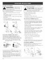
1
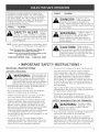
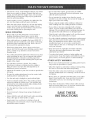
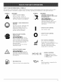
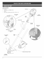
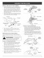
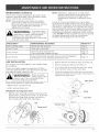
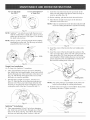
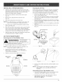
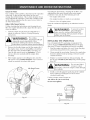
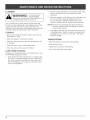
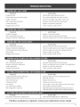
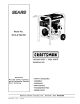
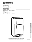
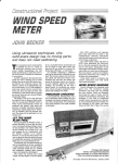
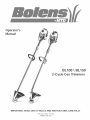
BL100
BL150
2-Cycle Gas Trimmers
iMPORTANT:
READ SAFETY RULES AND iNSTRUCTiONS
PiN 769-01464 (11/04)
PRINTED IN USA
CAREFULLY
THANK
YOU
TABLE OF CONTENTS
Thank you for buying this quality product. This modern
outdoor power tool will provide many hours of useful
service. You will find it to be a great labor-saving device.
This operator's
manual provides you with easy-tounderstand
operating
instructions.
Read the whole
manual and follow all the instructions to keep your new
outdoor power tool in top operating condition.
Service Information
.........................
Rules for Safe Operation
Know Your Unit
............................
Assembly Instructions
Oil and Fuel Information
PRODUCT REFERENCES,
AND SPECmFmCATmONS
mLLUSTRATmONS
All information, illustrations, and specifications
in this
manual are based on the latest product information
available at the time of printing. We reserve the right to
make changes at any time without notice.
Copyright¢_ 2004 MTD SOUTHWEST INC, All Rights
Reserved.
Bump Head TM is a trademark of MTD SOUTHWEST INC.
SplitLine TM is a trademark of MTD SOUTHWEST INC.
.....................
Starting/Stopping
6
7
......................
8
.................
......................
9
10
Maintenance and Repair Instructions ...........
11
Cleaning and Storage .......................
16
Troubleshooting
17
Specifications
Chart ......................
.............................
Warranty Information
18
.......................
Parts List ....................
SERVICE
3
.......................
Instructions
Operating Instructions
2
20
inside Back Cover
iNFORMATiON
Service on this unit both within and after the warranty
period should be performed only by an authorized and
approved service dealer.
For service call 1-800-520-5520
to obtain
authorized service dealers near you.
a list of
DO NOT RETURN THE UNiT TO THE RETAILER.
PROOF OF PURCHASE WiLL BE REQUIRED FOR
WARRANTY SERVICE.
Before beginning, locate the unit's model plate. It lists
the model and serial numbers of your unit. Refer to the
sample plate below and copy the information for future
reference.
S ....
Me_ei Number
erlai mumuer
--_
\
\MODEL:
ParentPart Number
/
S/N :
SPARK ARRESTOR
NOTE
NOTE: For users on U.S. Forest Land and in the
states of California, Maine, Oregon and Washington.
All U.S. Forest Land and the state of California (Public
Resources
Codes 4442 and 4443), Oregon and
Washington
require,
by law that certain
internal
combustion
engines operated on forest brush and/or
grass-covered areas be equipped with a spark arrestor,
maintained in effective working order, or the engine be
constructed,
equipped
and maintained
for the
prevention
of fire. Check with your state or local
authorities
for regulations
pertaining
to these
requirements. Failure to follow these requirements could
subject you to liability or a fine. This unit is factory
equipped
with a spark
arrestor,
if it requires
replacement, ask your LOCAL SERVICE DEALER to install
the Accessory Part #753-04689 Spark Arrestor Kit.
CALiFORNiA
PROPOSiTiON
65 WARNING
Copy the model and parent
part number here:
Copy the serial number
here:
Make sure you carefully read and understand this manual
before starting or operating this equipment.
THiS PRODUCT IS COVERED BY ONE OR MORE U.S.
PATENTS. OTHER PATENTS PENDING.
THE ENGINE EXHAUST FROM THiS
PRODUCT CONTAINS CHEMICALS
KNOWN TO THE STATE OF CALiFORNiA
TO CAUSE CANCER, BIRTH DEFECTS
OR OTHER REPRODUCTmVE HARM.
The purpose of safety symbols is to attract your
attention to possible dangers, The safety symbols,
and their explanations, deserve your careful attention
and understanding. The safety warnings do not by
themselves eliminate any danger, The instructions or
warnings they give are not substitutes for proper
accident prevention measures,
SYMBOL
SYMBOL
DANGER:
Failure to obey a
safety warning will
result in serious injury to yourself or to
others. Always follow the safety precautions
to reduce the risk of fire, electric shock and
personal injury,
MEANING
SAFETY ALERT: Indicates
danger,
WARNING:
NOTE: Advises you of information or instructions vital to
the operation or maintenance of the equipment.
, Failure to obey a
• safety warning may
result in property damage or personal injury
to yourself or to others, Always follow the
safety precautions to reduce the risk of fire,
electric shock and personal injury,
Read the Operator's Manual(s) and follow all
warnings and safety instructions.
Failure to do so can result in serious injury to the
operator and/or bystanders.
CALL
1o800o520o5520
,, iMPORTANT
READ
BEFORE
Fa,ure
to obey a
safetywarning can
resultininjury
to yourselfand others,
Always followthe safetyprecautionsto
reduce the riskof fire,
electric
shock and
personal injury,
warning or caution. Attention is required in
order to avoid serious personal injury. May
be used in conjunction with other symbols
or pbtographs.
FOR QUESTIONS,
MEANING
SAFETY
ALL iNSTRUCTiONS
OPERATING
WARNING:
When using the unit,
you must follow the
safety rules, Please read these instructions
the unit in order to ensure
operator and any bystanders,
Please keep these instructions for later use,
Read the instructions carefully. Be familiar with the
controls and proper use of the unit.
• Do not operate this unit when tired, ill or under the
influence of alcohol, drugs or medication,
Children under the age of 15 must not use the unit;
teens may operate the unit with adult guidance,
• Inspect the unit before use, Replace damaged parts,
Check for fuel leaks. Make sure all fasteners are in
place and secure, Replace cutting attachment parts
that are cracked, chipped or damaged in any way,
Make sure the cutting attachment is properly installed
and securely fastened, Be sure that the cutting
attachment shield is properly attached, and positioned
as recommended, Failure to do so can result in
personal injury to the operator and bystanders, as well
as damage to the unit.
Use only 0,080 inch (2,03 mm) diameter original
equipment manufacturer replacement line. Never use
metal-reinforced line, wire, chain or rope, These can
break off and become dangerous projectiles,
INSTRUCTIONS
o
Be aware of risk of injury to the head, hands and feet,
Clear the area to be cut before each use. Remove
rocks, broken glass, nails, wire, string and other
objects which may be thrown or become entangled in
the cutting attachment, Clear the area of children,
bystanders and pets; keep them outside a 50-foot
(15 m,) radius, at a minimum, Even then, they are still
at risk from thrown objects, Encourage bystanders to
wear eye protection, If you are approached, stop the
unit immediately,
Squeeze the throttle control and check that it returns
automatically to the idle position, Make all adjustments
or repairs before using the unit.
This unit was not designed to be used as a
brushcutter, Do not attach or operate this unit with any
type of brushcutting blade or brushcutting attachment,
SAFETY
WARNINGS
FOR GAS TRIMMERS
WARNING:
Gasoline is highly
flammable, and its
vapors can explode if ignited, Take the
following precautions:
• Store fuel only in containers specifically designed and
approved for the storage of such materials,
Always stop the engine and allow it to cool before
filling the fuel tank, Never remove the fuel tank cap or
add fuei when the engine is hot. Never operate the unit
without the fuel cap securely in place, Loosen the fuel
tank cap siowiy to relieve any pressure in the tank.
• Add fuel in a clean, welPventilated outdoor area where
there are no sparks or flames. Remove the fuel cap
slowly, and only after the engine stops. Do not smoke
while fueling or mixing fuel. Wipe up any spilled fuel
from the unit immediately.
• Avoid creating a source of ignition for spilled fuel. Do
not start the engine until fuel vapors dissipate.
• Move the unit at least 30 feet (9.1 m) from the fueling
source and site before starting the engine. Do not
smoke. Keep sparks and open flames away from the
area while adding fuel or operating the unit.
WHmLE OPERATmNG
• Never start or run the unit inside a closed room or
building. Breathing exhaust fumes can be fatal.
Operate this unit only in a well-ventilated outdoor area.
• Wear safety glasses or goggles that meet ANSI Z87.1
standards and are marked as such. Wear ear/hearing
protection when operating this unit. Wear a face or
dust mask if the operation is dusty.
• Wear heavy long pants, boots, gloves and a long
sleeve shirt. Do not wear loose clothing, jewelry, short
pants, sandals or go barefoot. Secure hair above
shoulder level.
The cutting attachment shield must always be in place
while operating the unit. Do not operate unit without
both trimming lines extended, and the proper line
installed. Do not extend the trimming line beyond the
length of the shield.
• This unit does not have a clutch. The cutting
attachment continues rotating when the engine is
idling. If it does not, have the unit adjusted by an
authorized service technician.
• Adjust the D-handb to your size in order to provide the
best grip.
• Be sure the cutting attachment is not in contact with
anything before starting the unit.
• Use the unit only in daylight or good artificial light,
• Avoid accidental starting. Be in the starting position
whenever pulling the starter rope. The operator and
unit must be in a stable position while starting. Refer
to Starting/Stopping Instructions.
• Use the right tool. Only use this tool for its intended
purpose.
• Do not overreach. Always keep proper footing and
balance.
Always hold the unit with both hands when operating.
Keep a firm grip on both handles or grips.
• Keep hands, face, and feet at a distance from all
moving parts. Do not touch or try to stop the cutting
attachment when it rotates.
• Do not touch the engine, gear housing or muffler.
These parts get extremely hot from operation, even
after the unit is turned off.
Do not operate the engine faster than the speed
needed to cut, trim or edge. Do not run the engine at
high speed when not cutting.
Always stop the engine when cutting is delayed or
when walking from one cutting location to another.
If you strike or become entangled with a foreign
object, stop the engine immediately and check for
damage. Do not operate before repairing damage. Do
not operate the unit with loose or damaged parts.
Stop the unit, switch the engine to off, and disconnect
the spark plug for maintenance or repair.
Use only original equipment manufacturer replacement
parts and accessories for this unit, These are available
from your authorized service dealer, Use of any
unauthorized parts or accessories could lead to
serious injury to the user, or damage to the unit, and
void your warranty,
Keep unit clean of vegetation and other materials.
They may become lodged between the cutting
attachment and shield.
To reduce fire hazard, replace a faulty muffler and
spark arrestor, Keep the engine and muffler free from
grass, leaves, excessive grease or carbon build up.
OTHER SAFETY
WARNmNGS
• Never store a fueled unit inside a building where fumes
may reach an open flame or spark,
Allow the engine to cool before storing or transporting.
Be sure to secure the unit while transporting.
Store the unit in a dry area, locked up or up high to
prevent unauthorized use or damage, out of the reach
of children.
Never douse or squirt the unit with water or any other
liquid. Keep handles dry, clean and free from debris.
Clean after each use, see Cleaning and .Storage
instructions.
Keep these instructions. Refer to them often and use
them to instruct other users. If you loan someone this
unit, also loan them these instructions.
SAVE THESE
SAFETY
AND
_NTERNAT_ONAL
SYMBOLS
This operator's manual describes safety and international symbols and pictographs that may appear on this product.
Read the operator's manual for compHete safety, assemMy, operating and maintenance and repair information.
SYMBOL
MEANING
MEANING
SYMBOL
SAFETY ALERT SYMBOL
,, THROWN OBJECTS AND
ROTATING CUTTER CAN CAUSE
SEVERE iNJURY
Indicates danger, warning, or
caution. May be used in conjunction
with other symboHs or pictographs.
WARNmNG:
WARNING - READ OPERATOR'S
MANUAL
Read the Operator's Manual(s) and
follow aH warnings and safety
instructions. FaiHureto do so can
resuHtin serious injury to the
operator and/or bystanders.
WEAR EYE AND HEARING
PROTECTION
WARNING: Thrown
Donot
operate without the cutting
attachment shieHd in pHace. Keep
away from the rotating cutting
attachment.
I
0
ON/OFF STOP CONTROL
ON / START / RUN
ON/OFF STOP CONTROL
OFF or STOP
objects and loud noise can cause
severe eye injury and hearing loss.
Wear eye protection meeting ANSI
Z87.1-1989 standards and ear
protection when
operating this unit. Use a full face
shield when needed.
,, HOT SURFACE WARNING
Do not touch a hot muffler or
cylinder. You may get burned. These
parts get extremely hot from
operation. When turned off they
remain hot for a short time.
', KEEP BYSTANDERS AWAY
WARNmNG: Keepa,
bystanders,
especially
children
and
pets,atleast
50 feet(I5 m.)fromthe
operating
area.
UNLEADED
FUEL
Alwaysuse clean,freshunleadedfuel.
1
2
1',1
• CHOKE
3
CONTROL
I ,, FULL choke position
2, PARTIAL choke position
3 o RUN position
', OIL
Refer to operator's
proper type of oil.
manual for the
APPUCAT_ONS
As a trimmer:
•
Cutting
FuemCap
grass and Hight weeds
Decorative
trimming
around
trees, fences,
etc.
Blue Choke
Lever
Starter
Rope Grip
Shaft
Grip "_
//
Primer
/
Bumb
D-Handle
Throttme
ControJ
On/Off
Stop
Controm
Spark Plug
Muffler
Air Filter/Muffler
Cover
Line Cutting
Blade
Shaft
Tube
Cutting Attachment
Cutting
Attachment
ShieH
INSTALL
AND ADJUST
THE D-HANDLE
Shaft Housing
3.
The squared boHthoHein the handHe is to the right.
2.
3.
Insert the shouHder boHt into the squared hoHein the
handHeand push through, On the Heftside of the
handHe, pHacethe washer on the boHt,then screw the
wing nut onto the boHt.Do not tighten untiHyou make
the handHeadjustment.
Cutting
Attachment
Cutting
Attachment
Shield
\
ShieJd
Mount
F_g. 2
Rotate the D-handHe to pHacethe grip above the top
of the shaft housing, Mace it a minimum of 6 inches
(15.24 cm) from the end of the shaft grip.
_He×
/
__
Lock Nut
Shaft Grip
Shaft Hous ,rig
_ DoHandle
Recessed
1.__
[nstammon a Curved
Bolt-------_f
v
4. While holding the unit in the operating position
(Fig, 2), position the D-handJe to the Jocation that
provides you the best grip.
Tighten the wing nut untiJ the D-handJe is secure.
THE CUTTING
SHIELD
Use the following instructions if the cutting attachment
shield on your unit is not installed or if you ever need to reinstall it,
WARNING:
Shaft (BL100)
1.
F_g.1
INSTALLING
Mace the cutting attachment shieHdonto the shaft
housing, Be sure the guard mounting bracket sHides
into the shot on the edge of the cutting shieHd.Rotate
the shieHdinto pHace,countercHockwise (Fig, 4). The
holies in the guard mounting bracket and cutting
attachment shieHdwill[ [ine up.
2. From inside the cutting attachment shieHd, push the
square boHtthrough the hoHeunti[ the threaded end
protrudes through the guard mounting bracket (Fig, 5),
3. Put the washer on the boHt,then screw the wing nut
onto the boHt and tighten.
Sha_ Housing_
Toprevent serious
personal injury,
Guard
Mounting
Bracket
never operate the trimmer without the
cutting attachment shield in place.
[nstammon a Straight
Shaft (BL150)
1. SHidethe cutting attachment shieHd into the shieHd
mount on the cutting attachment, AHignthe screw
holes in the shield with the holes in the cutting
attachment shieHd mount (Fig. 2).
2.
Homes
Tighten
Mace one of the three (3) suppHied hex Hocknuts into
one of the three recessed holies on the top of the
cutting attachment shieHd (Fig 3),
3.
[nstaHH
a screw into the hoHefrom the bottom of the
cutting attachment shieHd.Screw it into the nut instaHHed
in step 2 untiHit is started (Fig 3). Do not tighten.
4.
Repeat steps 2 and 3 untiH aHH
three screws have been
started. Then tighten aHH
screws secureHy with a
PhiHHipshead screwdriver.
Cutting
Attachment
Shield
F_g. 4
Guard
Mounting
Bracket
FTV_
\
• •
\
Wing Nut
Square Bolt
F_g.5
OraLAND
FUEL
MmXH_G
H_STRUCTmONS
ON and/or improperly mixed fuel are the main reasons
for the unit not running properly. Be sure to use fresh,
cban unleaded fuel. Follow the instructions carefully for
the proper fue%il mixture.
Definition
of Bmended Fuels
Today's fueis are often a bbnd of gasoiine and
oxygenates such as ethanol, methanol, or MTBE (ether).
AIcohol-bbnded fuel absorbs water. As littb as 1%
water in the fue[ can make rue[ and oi[ separate, it forms
acids when stored. When using alcohol-bbnded fuel,
use fresh rue[ (Hessthan 60 days oid).
ThorougHy mix the proper ratio of 2-cycb engine oil
with unleaded gasoline in a separate fuel can. Use a 40:1
fuel/oil ratio. Do not mix them directly in the engine fuel
tank. See the table below for specific gas and oil mixing
ratios.
NOTE: One gabn (3.8 liters) of unleaded gasoline mixed
with one 3.2 oz. (95 ml.) bottle of 2-cycb oil
makes a 40:1 fuel/oil ratio.
÷
Using Bmended Fuems
if you choose to use a bbnded fuel or its use is
unavoidabb, follow recommended precautions:
• AJways use the fresh fuel mix explained in your
operator's manual
• Always agitate the fuel mix before fueling the unit
, Drain the tank and run the engine dry before storing
the unit
Using
UNLEADED GAS
2 CYCLE OiL
1 GALLON US
(3.8 LITERS)
3.2FL OZ.
1 LITER
25 mm
MiXiNG
Fuem Additives
The bottle of 2-cycb oil that came with your unit
contains a fuel additive which will help inhibit corrosion
and minimize the formation of gum deposits, it is
recommended that you use our 2-cycb oil with this unit.
if unavailable, use a good 2-cycle oil designed for
air-coobd engines along with a fuel additive, such as
STA-B[L" Gas Stabilizer or an equivalent. Add 0.8 oz.
(23 ml.) of fuel additive per gallon of fuel according to the
instructions on the container. NEVER add fuel additives
directly to the unit's fuel tank.
, For proper engine
• operatbn and
maximum reliability, pay strict attentbn to
the oil and fuel mixing instructions on the
2-cycle oil container. Using improperly mixed
fuel can severely damage the engine.
(95rnm)
RATIO - 40:1
WARNING:
Gasoline
extremely
flammable, ignited Vapors may explode.
Always stop the engine and allow it to cool
the fuel tank. Do not smoke
WARNING:
Remove fuel cap
slowly to avoid injury
from fuel spray. Never operate the unit
without the fuel cap securely in place.
WARNING:
outdoor
Add fuel in a cban,
well ventilated
area. Wipe up any spilled fuel
until fuel vapors dissipate.
NOTE: Dispose of the old fuel/oil mix in accordance to
Federal, State and Local regulations.
_AIAD!_|
|_,|_,
Operate
thisunitonlyina
• well-ventilated
outdoor
area.Carbonmonoxide
exhaustfumescanbelethalin
a confined
area.
WARNING"•
On/Off Stop
Control
Avoid acddental starting.
Make sure you are in the
starting position when pulling the starter rope (Fig. 8).
To avoid serious injury, the operator and unit must be
in a stable position while starting.
STARTING
\
INSTRUCTIONS
Start/On
1,
Mix gas with oil. Fill fuel tank with fuel/oil mixture. See
Off and Fuel Mixing Instructions.
2.
Make sure the On/Off Stop Control in the ON ( I )
position (Fig. 6).
Fully press and release the primer bulb 10 times,
slowly. Some amount of fuel should be visible in the
primer bulb and fuel lines (Fig. 7). If you can't see fuel in
the bulb, press and release the bulb as many times as it
takes before you can see fuel in it.
4.
(I)
F_g. 6
Position 2
Position 1
Position
Place the blue choke lever in Position 1 (Fig. 7).
5. Crouch in the starting position (Fig. 8) and squeeze the
throttle control. Pull the starter rope out with a
controlled and steady motion 5 times.
NOTE: The unit uses E-Pull Version 3TM, which significantly
reduces the effort required to start the engine. You
must pull the starter rope out far enough to hear the
engine attempt to start. There is no need to pull the
rope briskly-- there is no harsh resistance when
pulling. Be aware that this starting method is vastly
different from (and much easier than) what you may
be used to.
6.
Place the blue choke lever in Position 2.
7.
While squeezing the throttle control, pull the starter
rope out with a controlled and steady motion until the
engine starts.
8.
Keep
warm
Place
ready
9.
_F,,,
__
the throttle squeezed and allow the engine to
up for 15 to 30 seconds.
the blue choke lever in Position 3. The unit is
for use.
Blue Choke
Lever
Primer Bulb
F_g. 7
Starting
Position
The engine does not start, go back to step 3.
IF... The engine fails to start after a
__
the blue choke lever in Position
throttle control. Pull the starter
times. The engine should start.
few attempts, place
3 and squeeze the
rope briskly 3 to 8
If not, repeat.
IF WARM...
If the engine is already warm, make sure the
On/Off Stop control is in the ON position and start the
unit with the blue choke lever in Position 2. After the
unit starts, move the blue choke lever to Position 3.
STOPPING
Starter Rope
iNSTRUCTIONS
1. Release your hand from the throttle control. Allow the engine
to cool down by idling.
2.
Put the On/Off Stop Control in the OFF (O) position.
Throttle Controt
F_g. 8
3
HOLDING
THE TRIMMER
WARNING:
NOTE: Do not rest the Bump Head TM on the ground
while the unit is running.
AHways wear eye,
hearing, foot and
body protection to reduce the risk of injury
when operating this unit,
Before operating the unit, stand in the operating position
(Fig. 9). Check for the following:
The operator is wearing eye protection and proper
clothing
• With a sHightHy-bent right arm, the operator's right hand
is hoHding the shaft grip
The operator's
the D-handHe
Heftarm is straight, the Hefthand hoHding
Some line breakage will occur from:
• Entanglement with foreign matter
Normal line fatigue
Attempting to cut thick, stalky weeds
• Forcing the line into objects such as walls or fence posts
• The unit is at waist HeveH
The cutting attachment is paraHeHto the ground and
easiHycontacts the grass without the need to bend over
BL150
personal inJury or damage to the unit,
BL100
TiPS
FOR BEST TRiMMiNG
• Keep the cutting attachment
RESULTS
parallel to the ground,
• Do not force the cutting attachment, Allow the tip of the
line to do the cutting, especially along walls. Cutting with
more than the tip will reduce cutting efficiency and may
overload the engine,
• Cut grass over 8 inches (200 mm) by working from top
to bottom in small increments to avoid premature line
wear or engine drag,
Cut from right to left whenever possible. Cutting to the left
improves the unit's cutting efficiency, Clippings are
thrown away from the operator,
Slowly move the trimmer into and out of the cutting
area at the desired height. Move either in a forwardbackward or side-to-side motion. Cutting shorter
lengths produces the best results,
Fig. 9
ADJUSTING
TRiMMiNG
• Trim only when grass and weeds are dry,
LiNE LENGTH
The Bump Head TM cutting attachment allows you to
release trimming line without stopping the engine. To
release more line, lightly tap the cutting attachment on the
ground (Fig, 10) while operating the trimmer at high speed,
NOTE: Always keep the trimming line fully extended,
Line release becomes more difficult as cutting
line becomes shorter
BL100
• The life of your cutting line is dependent upon;
Adherence of the listed trimming techniques
What
vegetation
is cut
Where vegetation is cut
For example, the line will wear faster when trimming against
a foundation wall as opposed to trimming around a tree,
DECORATIVE
TRiMMiNG
Decorative trimming is accomplished by removing all
vegetation around trees, posts, fences, etc,
Rotate the whole unit so that the cutting attachment
a 30 ° angle to the ground (Fig, 11),
BL150
Fig. 10
Each time the head is bumped, about 1 inch (25,4 mm)
of trimming line releases, A blade in the cutting
attachment shield will cut the line to the proper length if
any excess line is released,
For best results, tap the bump knob on bare ground or
hard soil, If you attempt a line release in tall grass, the
engine may stall, Always keep the trimming line fully
extended, Line release becomes more difficult when the
cutting line gets shorter,
10
\\
Fig. 11
is at
MAmNTENANCE
SCHEDULE
Perform these required maintenance procedures at the
frequency stated in the tame, These procedures shouHd
also be a part of any seasonaHtune-up,
NOTE: Some maintenance procedures may require
spedd tooHsor skills, If you are unsure about
these procedures take your unit to any non-road
engine repair estaMishment, individuaH or
authorized service dealer.
WARNING:
To prevent serious
injury, never perform
maintenance or repairs with unit running,
AHways service and repair a coo] unit,
Disconnect the spark phg wire to ensure that
the unit cannot start.
NOTE: Maintenance, rephcement, or repair of the
emission controH devices and system may be
performed by any non-road engine repair
establishment, individual or authorized service
dealer,
In order to assure peak performance of your engine,
inspection of the engine exhaust port may be necessary'
after 50 hours of operation. If you notice lost RPM, poor
performance or general lack of acceleration, this service
may be required, If you feel your engine is in need of this
inspection, refer service to any non-road engine repair
establishment, individual or authorized service dealer for
repair, DO NOT attempt to perform this process yourself
as engine damage may result from contaminants
involved in the cleaning process for the port,
FREQUENCY
MNNTENANCE
REQUIRED
Before starting engine
Fi[[ fuel tank with fresh fuel
Page 8
Every 10 hours
Clean and re-oil air filter
Page 13
Every 25 hours
Check and clean spark arrestor
Check spark plug condition and gap
Page 14
Page 15
Every 50 hours
Inspect exhaust port and spark arrestor screen for clogging or
obstruction to assure maximum performance levels
Page 14
UNE mNSTALLATmON
This section covers both SpHitLineTM and standard single
line installation,
Always use original equipment manufacturer 0,080 in,
(2.03 mm) replacement line, Line other than the specified
may make the engine overheat or fail,
WARNING:
Never
use
metalreinforced line, wire,
REFER
TO
2.
Remove the inner reel from the outer spool (Fig. 13),
3.
Remove spring from the inner reel (Fig, 13),
4.
Use a clean cloth to clean the the inner reel, spring,
shaft, and inner surface of the outer spool,
Check the indexing teeth on the inner reel and outer
spool for wear (Fig, 14). If necessary, remove burrs or
replace the reel and spool,
chain or rope. These can break off and
become dangerous projectiles.
Outer SpooJ
There are two methods to replace the trimming line:
Wind the inner reel with new line
• Install a prewound inner reel
Winding the Existing _nner Reel
1, Hold the outer spool with one hand and unscrew the
Bump Knob TM counterclockwise (Fig, 12). Inspect the
bolt inside the Bump Knob to make sure it moves
freely, Replace the Bump Knob if damaged,
Spring
\
\
Inner Reem
Fig. 13
Bolt
Indexing Teeth
Bump Knob TM
Fig. 12
Fig. 14
11
ForUsewithSingme
LineONLY
For Use with SplitLine TM
or SingmeLine
9.
Insert the end of the line into the open hole in the
inner reel and pull the line tight to make the loop as
small as possible (Fig. 18).
10. Before winding, split the line back about 6 inches.
11. Wind the line in tight even layers in the direction
indicated on the inner reel.
NOTE: Failure to wind the line in the direction indicated wi[[
cause the cutting attachment to operate incorrectly.
FWg.15
NOTE: SpHitLineTM can onHy be used with the unner tee[
with the shotted hones. SingHe[ine can be used on
either type of inner reel Use Figure 15 to identify
the inner tee[ you have.
Loop
NOTE: AHways use the correct [ine [ength when installing
trimming [ine on the unit. The [ine may not reHease
properHy if the [ine is too [ong.
Fig. 18
12. Insert the ends of the line into the two holding
(Fig. 19).
Loop
slots
13. Insert the ends of the line through the eyelets in the
outer spool and place inner reel with spring inside the
outer spool (Fig. 20). Push the inner reel and outer
spool together. While holding the inner reel and outer
spool, grasp the ends and pull firmly to release the
line from the holding slots in the reel.
Fig. 16
Single Line installation
Go To .Step 8 for 5pfitLine 7MInstallation
6. Take approximately 20 feet (6 m) of new trimming
line, loop it into two equal lengths, insert each end of
the line through one of the two holes in the inner reel
(Fig. 16). Pull the line through the inner reel so that
the loop is as small as possible.
7. Wind the lines in tight even layers, onto the reel
(Fig. 17). Wind the line in the direction indicated on
the inner reel. Place your index finger between the
two lines to stop the lines from overlapping. Do not
overlap the ends of the line. Proceed to step 11.
HoNing Slots
Fig. 19
NOTE: The spring must be assembled on the inner reel
before reassembling the cutting attachment.
14. Hold the inner reel in place and install the bump knob
by turning clockwise. Tighten securely.
Spring
Fig. 17
SpiitLine TM installation
8. Take approximately 10 feet (3 m) of new trimming
line. Insert one end of the line through one of the two
holes in the inner reel (Fig. 18). Pull the line through
the inner reel until only about 4 inches is left out.
12
"\\\
Fig. 20
mNSTALUNG
A PREWOUND
REEL
1. Hold the outer spool with one hand and unscrew the
bump knob counterclockwise (Fig. 12). Inspect the boHt
inside the bump knob to make sure it moves freeHy.
RepHacethe bump knob if damaged.
2.
Remove the oHdinner reeHfrom the outer spooH
(Fig. 13).
3.
Remove the spring from the oHdinner reeH
(Fig. 13).
4.
Mace the spring in the new inner reel
Cleaning the Air Filter
Clean and re-oil the air filter every 10 hours of operation.
It is an important item to maintain. Failure to maintain
your air filter properly can result in poor performance or
can cause permanent damage to your engine.
1.
NOTE: The spring must be assemMed on the inner reeH
before reassemMing the cutting attachment.
5.
Insert the ends of the Hinethrough the eyeHets in the
outer spooH (Fig. 20).
6.
Mace the new inner reeHinside the outer spool Push the
inner reeHand outer spooHtogether. WNe hoHdingthe
inner reeHand outer spool grasp the ends and pull firmly
to release the line from the holding slots in the spool.
7.
Hold the inner reel in place and install the bump knob
by turning clockwise. Tighten securely.
Remove air filter/muffler cover. Refer to Removing
the Air Filter/Muffler Cover.
2. Turn cover over and look inside to locate the air filter.
Remove the air filter from inside the air filter/muffler
cover (Fig. 22).
3. Wash the filter in detergent and water (Fig. 23). Rinse
the filter thoroughly. Squeeze out excess water. Allow
it to dry completely.
4. Apply enough clean SAE 30 oil to lightly coat the filter
(Fig. 24).
5. Squeeze the filter to spread and remove excess oil
(Fig. 25).
AIR FILTER MAINTENANCE
Removing the Air Filter/Muffler
Cover
Air FHter
WARNmNG: To
avoid
serious
personal injury,
always turn your unit off and allow it to cool
before you clean or service it.
Cover
Inside
Muffler
1. Place the blue choke lever in Position 2 (Fig. 21).
Fig. 22
NOTE: The blue choke lever must be in Position 2 to
remove the air filter/muffler cover.
2.
Remove the four (4) screws securing the air
filter/muffler cover (Fig. 21). Use a flat blade or
T-20 Torx bit screwdriver.
3.
Pull the cover from the engine. Do not force.
Fig. 23
/
Blue Choke
Lever
Position
2
Fig. 24
6.
Screws
Fig. 25
Replace the air filter inside the air filter/muffler cover
(Fig. 22).
Screws
NOTE: Operating the unit without the air filter and air
filter/muffler cover assembly will VOID the
warranty.
Reinstalling
the Air Filter/Muffler
Cover
1. Place the air filter/muffler cover over the back of the
carburetor and muffler. Align the screw holes.
Fig. 21
2.
Insert the four (4) screws into the holes in the air
filter/muffler cover (Fig. 21) and tighten.
13
SPARK
ARRESTOR
MAINTENANCE
WARNING:
1. Remove air fiHterimuffHercover. Refer to Removing
the Air Filter/Muffler Cover.
2.
3.
4.
5.
6.
7.
Mumer
Locate the muffHer, but do not remove it. Find the two
(2) screws on the bottom of the muffler (Fig. 26).
These two screws hoHdthe Spark Arrestor Hood
AssemMy and the spark arrestor screen to the
bottom of the muffler. Remove the two (2) screws
using either a torx #20 or flat Made screwdriver.
Using a small fiat Made screwdriver, carefully pry up
the spark arrestor screen from the recessed hoHe,
taking care to notice that the "raised" part of the
spark arrestor screen is inside the recessed hoHe.
Remove the spark arrestor screen from the muffler.
Spark Arrestor
Screen
,/
Place the spark arrestor plate on top of the spark
arrestor with the "raised" side up and the opening
facing towards the engine (Fig. 26).
Place the spark arrestor hood on top of the spark
arrestor plate with the "raised" side up and the
opening facing AWAY from the engine (Fig. 26). Verify
that the exhaust will be directed AWAY from the
engine.
Plate
Spark Arrestor
Opening
Engine
Recessed
CDan the spark arrestor screen with a wire brush.
Replace it if it is damaged, or if you are unable to
clean it thoroughly.
Reinstall the spark arrestor screen by putting the
"raised" portion of the screen inside the recessed
hole of the muffler. Make sure that the spark arrestor
screen fits flat against the muffler.
iftheexhaust
deflector assembly is
not tightened securely, it could fall offcausing
damage to the unit and possible serious
injury.
NOTE: The exhaust can onHyflow in one direction: AWAY
from the engine. Pay chose attention when
disassemMing the muffHer so you can put it back
together correctHy. FaiHureto do so will damage
the unit and may cause serious personaH injury.
Hole
"\
Spark Arrestor
Hood
Assembly
Includes:
Spark Arrestor PRate
Spark Arrestor Hood
and Screws
Spark Arrestor
Hood
Screws
Fig. 26
CARBURETOR
ADJUSTMENT
The idle speed of the engine is adjustable through the air
filter/muffler cover (Fig. 27).
8.
Replace the two screws you removed in Step 2 and
tighten them securely.
NOTE: Careless adjustments can seriously damage your
unit. An authorized service dealer should make
carburetor adjustments.
9.
Reinstall the air filter/muffler cover.
Check
Fuel Mixture
Old and/or improperly mixed fuel is usually the reason
for improper unit performance. Drain and refill the tank
with fresh, properly-mixed fuel prior to making any
adjustments. Refer to Oil and Fuel information.
14
Cmean Air Fimter
The condition of the air fiiter is important to the operation
of the unit, A dirty air fiiter will restrict air flow and
change the air/fuei mixture, This is often mistaken for an
out of adjustment carburetor, Check the condition of the
air fiiter before adjusting the idb speed screw, Refer to
Air Filter Maintenance,
Adjust Idle Speed Screw
If, after checking the fue[ mixture and cieaning the air
fiiter, the engine still[ will[ not idie, adjust the idie speed
screw as foiiows:
Checking the fuel mixture, cleaning the air filter, and
adjusting the idle speed should solve most engine
problems. If not and all of the following are true:
the engine wiii not idle
the engine hesitates or staiis on acceleration
there is a loss of engine power
Have the carburetor adjusted by an authorized service
dealer.
To prevent serious
personal injury,
make sure the cutting attachment has
pped rotating after you turn it off and
fou set it down.
1, Start the engine and bt it run at a high idle for a
minute to warm up, Refer to Stardng/Sto,oping
Instructions.
WARNmNG:
The cutting
attachment will spin
during idle speed adjustments. Wear
protective clothing and observe all safety
instructions to prevent serious personal injury.
2,
3,
Release the throttle trigger and let the engine idle, If
the engine stops, insert a small phillips screwdriver
into the hob in the air filter/muffler cover (Fig, 27).
Turn the idle speed screw in, clockwise, 1/8 of a
turn at a time (as needed) until the engine idles
smoothly,
If the engine appears to be idling too fast, turn the
idle speed screw counterclockwise
1/8 of a turn at
a time (as needed), to reduce idle speed,
REPLACING
THE SPARK
PLUG
Use a Champion RDJ7Y spark plug, or equiw_ient. The
correct air gap is 0.020 inch (0.5 rnrn}. Remove the plug
after every 25 hours of operation and check its condition.
1. Stop the engine and aiiow it to cooi. Grasp the plug
wire firmly and pull it from the spark plug.
2. Clean around the spark plug. Remove the spark plug
from the cylinder head by turning a 5/8-inch socket
counterclockwise.
3.
Idle Speed Screw
Replace a cracked, fouled or dirty spark plug. Set
the air gap at 0.020 in. (0.5 ram} using a feeler gauge
(Fig. 28).
the cylinder.
4.
Install a correctly-gapped spark plug in the cylinder
head. Tighten by turning the 5/8-inch socket
clockwise until snug.
If using a torque wrench torque to:
110-120 in.,ib. (12.3-13.5 N,m}
Do not over tighten.
Fig. 27
f
Fig. 28
15
CLEANING
WARNING:
To
serious
personal injury,
2. Start the engine and allow it to run until it stalls. This
ensures that all fuel has been drained from the
carburetor.
3_
always turn your trimmer off and allow it to
cool before you clean or service it,
Use a small brush to clean off the outside of the unit.
Do not use strong detergents. Household cleaners that
contain aromatic oils such as pine and lemon, and
solvents such as kerosene, can damage plastic housing
or handle. Wipe off any moisture with a soft cloth.
STORAGE
Never store a fueled unit where fumes may reach an
open flame or spark.
• Allow the engine to cool before storing.
Store the unit locked up to prevent unauthorized use
or damage.
• Store the unit in a dry, well-ventilated
area.
• Store the unit out of the reach of children.
LONG TERM STORAGE
If you plan on storing the unit for an extended time, use
the following storage procedure:
1. Drain all fuel from the fuel tank into a container with
the same 2-cycle fuel mixture. Do not use fuel that
has been stored for more than 60 days. Dispose of
the old fuel/oil mix in accordance to Federal, State
and Local regulations.
16
Allow the engine to cool. Remove the spark plug and
put 1 oz, (30 mi) of any high quaiity motor oil or
2-cycle oil into the cylinder, Puii the starter rope
siowiy to distribute the oii. Reinstaii the spark plug,
NOTE:
4_
Remove the spark plug and drain aii of the oii
from the cylinder before attempting
to start the
trimmer after storage.
Thoroughly clean the unit and inspect it for any loose
or damaged parts, Repair or replace damaged parts
and tighten loose screws, nuts or bolts. The unit is
ready for storage.
TRANSPORTING
• Allow the engine to cool before transporting.
• Drain fuel from unit.
Tighten fuel cap before transporting.
Secure the unit while transporting.
CAUSE
ACTION
Empty fueHtank
Fill
fueHtankwithpropedy mixed fueH
Primer buHbwasn't pressed enough
Press primer buHbfully and slowly 10 times
Engine is flooded
Squeeze the trigger and pull the starter rope
OHdor impropeHy mixed fueH
Drain gas tank and add fresh fuel mixture
FouHed spark pHug
Replace or clean the spark plug
Mugged spark arrestor
Clean or replace spark arrestor
CAUSE
ACTION
Air fiHteris pHugged
OHdor impropeHy mixed fueH
Replace or cleantheairfilter
Drain gas tank and add fresh fuel mixture
Improper carburetor adjustment
Adjust according to the Carburetor Adjustments
CAUSE
section
ACTION
OHd or improperlymixed fueH
Drain gas tank and add fresh fuel mixture
Improper carburetor adjustment
Take to an authorized service dealer for an adjustment
Cutting attachment
Stop the engine and clean the cutting attachment
bound with grass
Clean or replace the air filter
Mugged spark arrestor
Clean or replace spark arrestor
CAUSE
ACTION
OHd or improperlymixed fueH
Improper carburetor adjustment
Drain gas tank and add fresh fuel mixture
Take to an authorized service dealer for an adjustment
FouHed spark pHug
Replace or clean the spark plug
Mugged spark arrestor
Clean or replace spark arrestor
CAUSE
ACTION
Cutting attachment
Cutting attachment out of line
bound with grass
Stop the engine and clean cutting attachment
Refill with new line
Inner reel bound up
Replace the inner reel
Cutting head dirty
Clean inner reel and outer spool
Line welded
Disassemble, remove the welded section and rewind
Disassemble and rewind the line
Line twisted when refilled
Not enough line is exposed
Push the bump knob and pull out line until 4 inches
(102 mm) of line is outside of the cutting attachment
CAUSE
Oil, cleaner or lubricant in cutting head
ACTION
Clean and thoroughly dry the cutting head
If further
assistance
is required,
contact
your authorized
service
deaJer,
17
EngineType .................................................................................................
Air-CooHed,
2-Cycle
Stroke ...................................................................................................................................................
1.25 in. (31.75 mm.)
Displacement ............................................................................................................................................
1.9 cu in. (31 cc.)
Operating RPM ..................................................................................................................................................
7,200+ rpm
Idle Speed RPM ......................................................................................................................................
2,800 - 4,400 rpm
Ignition Type ..........................................................................................................................................................
Electronic
Ignition Switch ...............................................................................................................................................
Rocker Switch
Spark Hug Gap ......................................................................................................................................
0.020 in. (0.5 mm.)
Lubrication ...................................................................................................................................................
FueFOiHMixture
FueHiOiHRatio .................................................................................................................................................................
40:1
Carburetor .......................................................................................................................................
Diaphragm, AH-Position
Starter ...............................................................................................................................................................
Auto Rewind
Muffler .....................................................................................................................................................
BaffHed with Guard
ThrottHe ...............................................................................................................................................
FueHTank Capacity ...................................................................................................................................
Manual Spring Return
13 fl.oz. (384 mL)
Drive Shaft Housing ............................................................................................................................................
SteeHTube
ThrottHe ControH ........................................................................................................................................
Finger-Tip Trigger
Approximate Unit Weight (No fuel with cutting attachment, shieHd and D-handHe)....................................
10 Hbs.(4.5 kg.)
Cutting Mechanism ........................................................................................................................................
Bump Head TM
ShouHder Strap ........................................................................................................................................................
OptionaH
Line Spool Diameter ....................................................................................................................................
3 in. (762 mm.)
Trimming Line Diameter .......................................................................................................................
0.080 in. (2.03 mm.)
Cutting Path Diameter ..............................................................................................................................
17 in. (43.18 cm.)
+All specifications are based on the latest product information available at the time of printing. We reserve the right to
make changes at any time without notice.
18
California
/ EPA Emission
Your Warranty
ControJ
Rights
Warranty
Statement
and Obligations
The California Air Resources Board, the Envkonmentd Protection Agency and MTD LLC (MTD) are pHeased to exphin
the emission controH system warranty on your 2000 and Hatersmall off-road engine, New small off-road engines must be
designed, buiHtand equipped to meet stringent anti-smog standards, MTD must warrant the emission controH system on
your small off-road engine for the periods of time Histed bellow provided there has been no abuse, negHect or improper
maintenance of your small off-road engine,
Your emission controH system may include parts such as the carburetor or fueNnjected system, the ignition system, and
cataHytic converter, AHso incHuded may be hoses, beHts, connectors and other emission-related assemblies,
Where a warrantable condition exists, Troy-Bilt will repair your small off-road engine at no cost to you
diagnosis, parts and labor,
The 2000 and later small off-road engines are warranted for two years, If any emission-related
defective, the part will be repaired or replaced by Troy-Bilt.
part on your engine is
Owners Warranty
Responsibilities
• As the small off-road engine owner, you are responsible for the performance of the required maintenance listed in your
operator's manual, Troy-Bilt recommends that you retain all receipts covering maintenance on your small off-road
engine, but Troy-Bilt cannot deny warranty solely for the lack of receipts or for your failure to ensure the performance of
all scheduled maintenance,
As the small off-road engine owner, you however should be aware that Troy-Bilt may deny you warranty' coverage if
your small off-road engine or a part has failed due to abuse, neglect, improper maintenance or unapproved
modifications,
• You are responsible for presenting your small off-road engine to a Troy-Bilt Authorized Service Center as soon as a
problem exists, The warranty repairs should be completed in a reasonable amount of time, not to exceed 30 days,
If you have any questions regarding your warranty rights and responsibilities,
you shouM ca[[ 1-800-520-5520,
Manufacturer's
Warranty
Coverage
• The warranty period begins on the date the engine or equipment is delivered to the retail purchaser,
• The manufacturer warrants to the initial owner and each subsequent purchaser, that the engine is free from defects in
material and workmanship which cause the failure of a warranted part for a period of two years,
Repair or replacement of warranted part will be performed at no charge to the owner at an Authorized Troy-Bilt Service
Center, For the nearest location please contact Troy-Bilt at: 1-800-520-5520,
, Any warranted part
for regular inspection
warranted part which
to the first scheduled
which is not
to the effect
is scheduled
replacement
scheduled for replacement, as required maintenance or which is scheduled for only
of "Repair or Replace as Necessary" is warranted for the warranty period, Any
for replacement as required maintenance will be warranted for the period of time up
point for that part,
The owner wi[[ not be charged for diagnostic [abor which [eads to the determination
if the diagnostic work is performed at an Authorized Troy-Bilt Service Center,
• The manufacturer
under warranty,
that a warranted part is defective,
is liable for damages to other engine components caused by the failure of a warranted part still
• Failures caused by abuse, neglect or improper maintenance are not covered under warranty,
, The use of add-on or modified parts can be grounds for disallowing a warranty claim, The manufacturer
cover failures of warranted parts caused by the use of add-on or modified parts,
is not liable to
, In order to file a claim, go to your nearest Authorized Troy-Bilt Service Center, Warranty services or repairs will be
provided at all Authorized Troy-Bilt Service Centers,
• Any manufacturer approved replacement part may be used in the performance of any warranty maintenance or repair
of emission related parts and will be provided without charge to the owner, Any replacement part that is equivalent in
performance or durability may be used in non-warranty maintenance or repair and will not reduce the warranty
obligations of the manufacturer
• The following components are included in the emission related warranty of the engine, air filter, carburetor,
lines, fuel pick up/fuel filter, ignition module, spark plug and muffler,
primer, fuel
19
MANUFACTURER'S
LIMITED WARRANTY FOR:
The limited warranty set forth below is given by Troy-Bilt
LLC with respect to new merchandise purchased and used
in the United States, its possessions and territories.
Troy-Bilt LLC warrants this product against defects in
material and workmanship for a period of two (2) years
commencing on the date of original purchase and will, at its
option, repair or replace, free of charge, any part found to
be defective in material or workmanship.
This limited
warranty shall only apply if this product has been operated
and maintained in accordance with the Operator's Manual
furnished with the product, and has not been subject to
misuse, abuse, commercial
use, neglect, accident,
improper maintenance, alteration, vandalism, theft, fire,
water or damage because of other peril or natural disaster.
Damage resulting from the installation or use of any'
accessory or attachment not approved by Troy-Bilt LLC for
use with the product(s) covered by this manual will void
your warranty as to any resulting damage. This warranty' is
limited to ninety (90) days from the date of original retail
purchase for any Troy-Bilt product that is used for rental or
commercial purposes, or any other income-producing
purpose.
BOW TO OBTAIN SERVICE:
Warranty
service is
available, WITH PROOF OF PURCHASE THROUGH
YOUR LOCAL AUTHORIZED SERVICE DEALER. To locate
the dealer in your area, visit our website at w_.troybilt.com,
check for a listing in the Yellow Pages, call 1-800-5205520 or write to P.O. Box 361131, Cleveland, OH 441360019.
This limited warranty
the following cases:
A. Tune-ups
Filters
B.
C.
does not provide
- Spark Plugs, Carburetor
coverage
in
Adjustments,
Wear items - Bump Knobs, Outer Spools, Cutting
Line, Inner Reels, Starter Pulley, Starter Ropes, Drive
Belts
Troy-Bik
LLC does not extend any warranty for
products sold or exported outside of the United
States of America, its possessions and territories,
except those sold through Troy-Bilt's
authorized
channels of export distribution.
Troy-Bilt LLC reserves the right to change or improve the
design of any Troy-Bilt Product without assuming any
obligation to modify any product previously manufactured.
No implied warranty, including any implied warranty of
merchantability
or fitness for a particular
purpose,
applies after the applicable period of express written
warranty above as to the parts as identified. No other
express warranty or guaranty, whether written or oral,
except as mentioned above, given by any person or
entity, including a dealer or retailer, with respect to any
product shall bind Troy-gilt LLC During the period of
the Warranty,
the exclusive
remedy is repair or
replacement of the product as set forth above. (Some
states do not allow limitations on how long an implied
warranty lasts, so the above limitation may not apply to
you,)
The provisions as set forth in this Warranty provide the
sole and exclusive remedy arising from the sales. Troygilt LLC shall not be liable
for incidental
or
consequential
loss or damages including,
without
limitation,
expenses
incurred
for substitute
or
replacement lawn care services, for transportation
or
for related expenses,
or for rental expenses
to
temporarily replace a warranted product. (Some states
do not allow limitations on how long an implied warranty
lasts, so the above limitation may not apply to you.)
In no event shall recovery of any kind be greater than the
amount of the purchase price of the product sold.
Alteration of the safety features of the product shall void
this Warranty. You assume the risk and liability for loss,
damage, or injury to you and your property and/or to
others and their property arising out of the use or misuse
or inability to use the product.
This limited warranty shall not extend to anyone other than
the original purchaser, original lessee or the person for
whom it was purchased as a gift.
Bow State Law Relates to this Warranty: This warranty
gives you specific legal rights, and you may also have
other rights which vary from state to state.
To locate your nearest set_iice dealer dial 1-800-520-5520.
Troy-Bitt LLC
P.O. Box 361131
Cleveland, OH 44136-0019