1
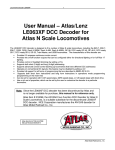
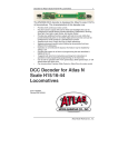
ADDING MORE POWER TO YOUR LAYOUT
Trains (especially those with lights) consume a lot of power. The Commander
delivers a maximum of 2.5 Amps of current to your layout. If your locomotives and cars use more then 2.5 Amps, it is necessary to split the layout in
several power sections and feed each section with an extra "booster" which
provides more amperage. Terminals C & D on your Commander can be used
to wire in extra boosters. For more information about adding power stations
to your layout, please see the DCC section of Atlas' web site at
www.atlasrr.com.
INSTRUCTION MANUAL
LIMITED ONE-YEAR WARRANTY
Atlas Model Railroad Company, Inc. warrants that this Commander will be free from defects in
material and workmanship for a period of one year from the date of purchase. If this
Commander fails during the warranty period, carefully pack the item in the original carton,
together with the dated sales receipt, and return to: Atlas DCC Warranty, 603 Sweetland
Avenue, Hillside, NJ 07205. Defects due to misue, improper maintenance and/or abuse are not
covered by the warranty. Items that have been disassembled by the modeler or anyone other
than an authorized Atlas repair person are not covered by the warranty. This warranty gives
you specific legal rights and you may also have other rights which vary from state to state.
The Atlas Master DCC Commander complies with Part 15 of FCC Rules. Operation is subject to
the following two conditions: (1) this device may not cause harmful interference, and (2) this
device must accept any interference received, including interference that may cause undesired
operation.
FOR TECHNICAL ASSISTANCE:
www.atlasrr.com
[email protected]
Atlas Model Railroad Co, Inc. • 603 Sweetland Ave. • Hillside • NJ • 07205
ITEM #330
WELCOME TO THE ATLAS MASTER™ DCC SYSTEM!
TABLE OF CONTENTS
Getting Started...................................................................... 3
Decoder Preparation...3
Setting Up Your Layout To Run DCC...3
The Atlas Master DCC System and the related components have been designed to be
fun and easy to use so you can enjoy running your trains using the latest in digital
command control technology. Not only do you not have to be an electrical engineer,
but you will be running your trains in DCC mode in no time, if you follow the
Commander instructions contained in this manual.
Using the Atlas Master DCC Commander.................................. 5
Locomotive Addressing....5
Running Your Locomotive........................................................ 6
Controlling Speed...6
Changing Directions...6
Activating Functions...7
Emergency Stop...8
ATLAS MASTER DCC SYSTEM COMPONENTS
The Menu System................................................................... 9
Accessing the Menu...9
Menu Selections...10
Controlling Turnouts...10
Setting Speed Steps...11
Decoder Programming...12
System Settings...15
The following is all you need to get started running your trains in
Digital Command Control:
1. Commander*: Controls your trains. Item #330
2. Generator*: Provides power to the Commander. Item #335
3. Decoder*: Atlas offers an HO scale multi-function Dual-Mode
Decoder™ that, once installed, allows you to easily switch the operation of
your locomotive from analog to digital mode. This function enables you to
run your decoder-equipped engines on an analog layout without the typical
speed differential. N scale multi-function decoders are also available. Some
HO & N scale Atlas locomotives have decoders factory-installed, for your
convenience. See our web site for further details. www.atlasrr.com
* The Atlas Master DCC System components follow the NMRA DCC standards
and are also compatible with items from other DCC manufacturers.
Expanding Your System.........................................................16
Adding Additional Throttles...16
Connecting Two Commanders...17
Characteristics of the Slave Commander...18
Adding More Power to Your Layout (Power Stations)...Back Cover
MISCELLANEOUS ITEMS YOU WILL ALSO NEED:
• Atlas Colored Layout Wire: (or any18-20 gauge stranded wire). Items
#315-#319
• Terminal Joiners: HO - Item #842; N scale - Item #2539
Recalling Locomotives (“stack” function)................................. 8
1
2
• Insulated Rail Joiners: HO - Item #55; N scale - Item #2538
• Mini flathead screwdriver
GETTING STARTED
Decoder Preparation
Before you can use your Commander, you must have a decoder installed in
any locomotive you wish to run in DCC mode. Please note that Atlas DualMode Decoders factory-installed in HO scale Atlas locomotives come set-up in
Analog mode. To switch from Analog to Digital mode, please refer to the
instructions that came with your locomotive.
Setting Up Your Layout to Run DCC
Any analog layout that is run using a standard DC power pack can be converted to run as a digital layout controlled by a DCC system. Here are the steps
to convert your layout to run DCC using the Atlas Commander:
3. Create a Programming Track Section. The programming track section
allows you to program your decoder-equipped locomotive. First, you must isolate a section of track from your mainline (such as a siding), using plastic insulated rail joiners. Second, connect the non-insulated end of your programming
track section (using terminal joiners or other track leads) to screw terminals P
& Q on the Commander. If you prefer, you can use an Atlas Selector (Item
#215) toggle switch to apply mainline track power or programming track
power to the insulated track section.
4. Plug the Power Cord of the Generator into a 120VAC power
outlet (US standard).
Please note that terminals C & D may be used to add additional Power
Stations. Please see page 18 for an explanation of Power Station usage.
*CAUTION: If you use
(See Fig. 2 on page 4 for location of terminals on the Commander.)
1. Connect the Generator to the Commander. Connect terminals U & V
on the Commander to the output terminals of the Generator, using stranded
18-20 gauge wire. Please note that you may use any 14 to 16VAC, 14 to
18VDC, 45va to 55va transformer in place of an Atlas Generator.
2. Connect the Commander to your track leads. Connect the wires from
your terminal joiners, or other track leads, to screw terminals J & K on the
Commander. Use 18-20 gauge stranded wire to extend your leads, if necessary. IF YOU NEED ADDITIONAL INFORMATION, PLEASE SEE www.atlasrr.com
(in DCC section).
3
FIGURE 2
an Atlas Selector and your
layout is using common
rail wiring, as in all Atlas
layout plans, P & J must
go to common rail.
Terminal Q & K must go to
the A & B input of the
Selector. Otherwise an ER1
message will be displayed.
4
NOW YOU'RE READY TO RUN YOUR
TRAINS WITH DCC!
USING THE ATLAS MASTER DCC COMMANDER
Buttons And Their Function
Dial - Used to control the speed of the selected engine.
and - Used to select the direction of the selected engine. Pressing both
buttons together to access the Menu system.
Stop - This emergency Stop button is used to turn the track power on and off.
F0, F1, F2 - Used to access the first three functions of a decoder, if the
decoder has three-function capability. As you can see, the F0 button also functions as the Enter button, when you are in the Menu system. In the same way,
F2 also functions as the Exit button.
"+" and " -" - Used to scroll to the decoder address you wish to control, or
to scroll through menu options when you are in the Menu system.
Understanding Locomotive Decoder Addressing
Each decoder-equipped locomotive has an address. The address is how the
Commander identifies which locomotive it is controlling at any given time.
Using the Commander you can easily control the speed, lights, and other functions (if available) of up to 99 engines!
Most decoders come set to the default address of “03.”
To program a locomotive's address, go to page 13
5
RUNNING YOUR LOCOMOTIVE
When you turn the Commander "on," the display will default to L03
(Locomotive - 03). To select the locomotive you want to run by selecting its
address in the Commander display, use the + and - buttons. If the key remains
pressed, the addresses will scroll up or down quickly. Once you've reached the
desired address, that becomes the "selected" locomotive, which can be controlled using the dial.
Controlling the Speed of Your Locomotive
The speed of the selected locomotive is controlled with the dial. Turning the
dial clockwise increases speed, turning it counter clockwise decreases the
speed. In full counter clockwise (ccw) position the locomotive stops and full
clockwise position sets maximum speed.
Changing Directions
The and buttons are used to control the direction of the selected locomotive:
Key
Display
.
L 03
L .03
Forward - A dot will appear to the
upper left of the centermost LED.
Backward - A dot will appear to the
lower left of the centermost LED.
The direction of travel changes only after the key is released. The display will
show the selected direction.
6
If you change the direction while the engine is still moving (speed dial not
fully ccw), the locomotive will decrease speed (brake) with the preset deceleration value until it comes to a full stop and then accelerate in the opposite
direction with the preset acceleration speed. For more information on acceleration and deceleration speed (and programming same), see page 11.
Activating Functions
Buttons F0, F1 and F2 are used to activate functions on the selected locomotive, to control turnouts or other accessories via an accessory decoder. For
information on controlling your turnouts, please see page 10.
Function zero - F0 - controls the headlights and rear lights. (which lights illuminate depends on the direction the locomotive is travelling). Function one F1 - and function two - F2 - may be configured by the user. Use of F1 and
F2 depend on the capability of the decoder (additional wiring required).
Examples of additional functions that could be assigned to F1 and/or F2
would be sound (bells, horn, whistles) and/or ditch lights. You must consult
your decoder’s manual for information on its functionality.
Pressing the button once activates the function, and the second press turns it
off. All functions can be activated or de-activated independently of each other
so you may have two or three functions on at one time, if desired.
The display to the right (top) shows if a function is active or not:
7
Active
Function
F0
F1
F2
Display
.
L. 03
.
L 0.3
.
L 03.
If function F0 is active, a dot is displayed to the
lower right of the leftmost LED.
If function F1 is active, a dot is displayed to the lower
right of the center LED.
If function F2 is active, the dot is displayed to the lower
right of the rightmost LED.
Emergency Stop
In case of a foreseeable train crash, operation can be stopped by pressing the
Stop key:
Key
Stop
Stop
Display
OFF
.
L. 29
The display shows a flashing "OFF".
The power to the track is turned off.
Pressing the Stop key again restores power to the track.
All locomotives running prior to pushing Stop will start up
and accelerate to the last set speed.
RECALLING LOCOMOTIVES
The Commander has a “stack” feature which remembers the last eight locomotives accessed. To recall a locomotive from the stack, press either the
or
(depending on the direction the locomotive is traveling) and then
the “+” or “-” button to scroll through the stack until you reach the
8
desired locomotive. Since the stack only remembers eight locomotives, when
you access the 9th engine the first engine in the stack will drop out. For example, in a stack of 1,2,3,4,5,6,7,8, if you access another locomotive (ie., locomotive 9), the stack will forget locomotive 1 and remember 2,3,4,5,6,7,8,9.
When acquiring a locomotive that is currently running:
1. Scroll with the + or - keys to the desired locomotive address or recall from
the stack as described on page 8.
2. Press and hold the direction button, forward or reverse , which
corresponds to the direction the locomotive is moving.
3. Set the dial to approximately the same speed the engine is moving.
4. Release the direction button to take control of the locomotive.
THE MENU
Menu Selections
This menu is used to throw turnouts, or control other accessories.
NOTE: You must have an accessory decoder attached to one or
more turnouts on your layout for this function. For more about
controlling turnouts, see below.
SPE
.
SY S
This menu is used to select the speed steps of the selected
locomotive decoder.
This menu is used to display or program a decoder and its
parameters.
This menu is used to change the system settings.
Controlling Turnouts
Accessing the Menu
If you have accessory decoders installed on your layout to control your
turnouts, you must first assign each an address through programming.
Accessory decoders are programmed just like a locomotive decoder (consult
the paperwork supplied with the accessory decoder for programming instructions). After the required programming, you can use the Function buttons on
your Commander to control the turnouts, as described below.
Press both and buttons at the same time to access the Menu system. The
display changes and now shows the last used menu. You may scroll through
the menu choices using the + and - buttons.
1. Press both and buttons at the same time to access the Menu system.
2. Press the "+" or "-" buttons until the Turnout menu is displayed, then
follow the steps below:
The Commander has a Menu System which is used for the following settings and functions:
• Controlling turnouts • Adjust system settings • Setting speed steps
• Programming and reading decoder addresses and parameters
When you reach the desired menu, press the Enter key to access the settings
in that menu, or Exit to leave the menu and go back to the previous selection options or the last selected locomotive.
9
10
Display
What To Do
Press Enter to go to the Turnout (switch) menu.
Press the +/- key to scroll through the switch addresses until
you arrive at the address of the turnout you want to switch.
(Possible range is 0 through 99)
When you get to the desired turnout number:
F0 - Sets selected turnout to the siding or reverse route
F1 - Sets selected turnout for mainline or normal route
During the time you are in the Turnout menu, you can control the speed of the
locomotive that was last selected using the dial.
Speed Step Assignment
The speed range from a complete stop to maximum speed is set up in steps.
The larger the number of steps, the higher the resolution of the speed range.
In other words, the larger the speed step, the more control you will have over
how smooth your locomotive will run as it accelerates/decelerates. The
Commander supports three different speed step modes: 14, 28 and 128 speed
steps. The speed step setting is relative to a locomotive decoder address.
Therefore, when you follow the steps below, you will be programming the
speed steps for the selected locomotive decoder.
Setting Speed Steps
1. Press Exit until you are back at the Locomotive address display [L ##].
Scroll using + and - until you arrive at the desired locomotive address.
2. To Enter the Menu System, press both
11
and
buttons at the same time.
Press the + or - button until the Speed Step menu is displayed.
Display
What To Do
SPE
.
28
.
28
.
4
Press Enter to access the speed step menu.
The display shows the current speed step setting for the
selected locomotive address.
Press +/- until you arrive at the desired speed step (14, 28 or
128 are your options)
Once the desired speed step appears, press Enter.
3. Press Exit. Note that pressing Exit before pressing Enter will result in
leaving the speed step menu without making any changes.
Important Hints
• If the speed of the selected locomotive is not off (dial not fully ccw), the
current speed step can be viewed but not changed.
• Verify that the decoder of a locomotive can "understand” the speed step
modes (consult your decoder manual).
Programming Your Decoder
If you wish to operate two or more individual locomotives at a time, each locomotive decoder must have a unique address. The address of a decoder is
changed by programming. Remember that there are two kinds of decoders:
those that are installed into locomotives, and those that are "accessory" or
“stationary” and are used to control turnouts or other accessories on your lay12
out. The following characteristics (parameters) of a decoder can be viewed* or
edited through the Programming menu.
The parameters are stored in "Registers," each having its own number:
PARAMETER
Address
Start up voltage
Start up delay (acceleration)
Brake delay (deceleration)
General settings
Version number of decoder
software*
Manufacturer ID*
REGISTER NUMBER CONFIGURATION VARIABLE
R1
R2
R3
R4
R5
1
2
3
4
29
R7
R8
7
8
Programming A Locomotive’s Decoder Address
1. Put your locomotive on the programming track. For information on creating a programming track, see page 3.
2. Press both and buttons at the same time to access the Menu system.
Press the "+" or "-" button to scroll to the Programming menu.
Display
What To Do
Press Enter to go into Programming mode.
Press Exit to leave the menu.
The first time you enter Programming mode, Register 1
(Address#) is displayed. To program your locomotive’s decoder
address, press Enter. To enter a different Register, press "+", or “-”.
To read out the current value of the selected register, press
Enter (in this case, the current locomotive decoder address). If
the read-out is successful, the locomotive’s decoder address is
displayed. If there is an error, an error message will be
displayed (see page 4 for an explanation).
We will discuss programming a decoder's address. Follow the same steps for
programming registers 2 through 5. See your decoder manual for the range
of data and default settings of each register. *Registers 7 & 8 are read only.
NOTE: The Atlas Commander uses Register Mode Programming.
STEP-BY-STEP DECODER PROGRAMMING
Please Note: Operation of the layout is disabled during programming (track
power is turned off). Connected slaves receive a signal through the communication cable about the pending programming. For more information about
slaves, please see page 18.
You may use these instructions to program a decoder installed in a locomotive, or an accessory decoder that will be used to control turnouts. In the
example below, we guide you through programming the address of a locomotive decoder. You would follow the same steps to program registers 2
through 5, or an accessory decoder.
13
Display
.
L 03
L
.
What To Do
To change the value (locomotive address number in this case),
use the +/- button to scroll. For locomotive addresses you are
able to program in the range of 0 to 255. *Please note that the
Commander can access addresses 0 to 99. (Consult the decoder
manual for the variable range of other Registers.)
Press Enter to "OK" the desired locomotive address. After
programming is complete, the new value is displayed. In case
of an error, a message is displayed (see below).
Press Exit to go back to the Register display. You can select
another register (using +/-) or get back to the Menu selection
by pressing Exit.
14
Press Enter to view the version number. You cannot
change this value; it is read-only. Press Exit to go back to
System menu.
Error Messages:
Display
E
E 2
Error Description
A short circuit has been detected on the programming track.
Check relevant connections and/or decoder installation in the
locomotive.
No value was found during the readout of a Register, or no
response was received after a value was entered. However, this
does not necessarily mean the decoder did not accept the new
values. Please try using the new address before attempting to
program again. You should also check if the locomotive is on
the right programming track and/or the installation of the
decoder.
System Settings
The following system parameters can be edited or viewed:
• Version number of the Commander software (view only).
• Service number of the Commander. You will be asked to identify this
number if you call in for assistance with your Commander.
• If your Commander is set to function as a master or as a slave (also called
an XpressNET unit).
1. Press both and buttons at the same time to access the Menu system.
Use the "+" or "-" buttons to scroll to the System menu.
Display
What To Do
.
SY S
.
Y
15
Press Enter to select the System mode setting.
The first system setting (shown to left) is the Commander
software version number setting option.
.
Y 2
02
.
Y90
Press +/- buttons until you see the service number system
setting option (shown on left).
Press Enter to view the service number. You cannot
change this value; it is read-only. Press Exit to go back to the
System menu.
Press "+" or "-" button until you see the Master/Slave system
setting (shown on left). Press Enter to select setting options.
Press "+" or "-" button to scroll through the options. To make
your Commander operate in master mode, press Enter when
you see the display on left.
To have your Commander operate in slave mode, press Enter
when you see display on left. Press Exit to leave the menu.
EXPANDING YOUR SYSTEM
Adding Additional Throttles
If you would like to have more than one operator on your layout, you may
connect up to five additional Commanders or handhelds that conform to
XpressNET standards to your original unit. When you have more than one
Commander, one becomes the "master" and the other(s) become "slaves." The
master provides track power, the slaves do not. Any Commander (master or
slave) that is connected to a Generator may be used for programming. In the
case of a slave that is used for programming, it must be connected to a programming track via output terminals P & Q and must be connected to a
16
Generator. Both master and slaves have the ability to control speed and functions of all addressed locomotive and accessory decoders.
The connection between the (Master) Commander and a (Slave) Commander
is established through a communication cable, referred to as the XpressNET.
This XpressNET cable is a standard modular RJ45 wire cable with 6-conductor
wire/connectors (much like a phone cord, with an RJ45 pin instead of the
standard phone pin).
Connecting Two Commanders (Using One Generator)
1. When adding an additional Commander to your system, it must be
configured to operate as a slave. Connect the Commander you wish to use
as a slave, to the Generator (power supply).
2. On the slave unit, press both and buttons at the same time to access
the Menu system. Press “+” or “-” until you get to the system menu. Press
Enter.
3. Press “+” or “-” until you see "Y90", and press Enter. Press “+” or “-”
until you see "con" (small con) on the display. Press Enter. You have now
set that Commander to operate as a slave.
4. Press Exit until you are back at the main System menu (display reads
"Y90").
5. Use +/- to scroll to "Y10" and Press Enter. You are now in the menu that
will set the address of the slave.
6. Using the +/- to scroll, set the address of the slave Commander.
Available values are 1 through 31. When you are at the desired address,
press Enter.
17
7. Press Exit on the slave until you are back at the main Locomotive
address display.
8. Disconnect the slave Commander from the Generator.*
9. Connect the master Commander to the Generator.
10. Connect the slave Commander to the master, using the XpressNET cable.
Now you can control locomotives and turnouts from either Commander.
*If you intend to use a slave Commander for programming do not
disconnect it from the Generator.
CHARACTERISTICS OF THE SLAVE COMMANDER
• The slave Commander cannot be used to power the track.
• The slave does not require an additional Generator (power supply), but can
be hooked up to a Generator to provide it with programming capabilities.
• If the slave is connected to a Generator, it still cannot be used to power the
track. HOWEVER, if you power both the master and the slave, the track
will be powered while you are programming.
• When you are in the System (SYS) menu, you will see an additional setting
- "Y13." When you see this, press Enter to read the version number of the
master.
• Display of the version number: n30 = Unit is operating as a slave without
its own power supply.
Error Messages:
• Er99 : No XpressNET-connection
18