1
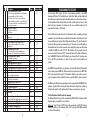
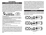
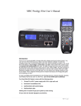
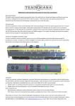
USER MANUAL
LIMITED ONE-YEAR WARRANTY
ATLAS HO DUAL-MODE™ 4-FUNCTION DECODER - ITEM #342
Atlas Model Railroad Company, Inc. warrants that this decoder will be free from
defects in material and workmanship for a period of one year from the date of purchase. If this decoder fails during the warranty period, uninstall and carefully pack
the item in the original carton, together with the dated sales receipt, and return to:
Atlas, 378 Florence Avenue, Hillside, NJ 07205. Defects due to misuse, improper
maintenance and/or abuse are not covered by the warranty. This warranty gives you
specific legal rights and you may also have other rights which vary from state to state.
Atlas’ HO 4-Function Dual-Mode Decoder (DMD) presents a whole new concept in the
evolution of DCC. Modelers are able to run a decoder-equipped locomotive on a standard DC powered (analog) layout, without experiencing the typical speed differential.
Although this decoder was designed for use with our own Atlas Master DCC System, it
is also compatible with other DCC systems that are NMRA compliant. It can also be
installed into any locomotive with a motor-mounted light board, which includes almost
all Atlas engines produced since 1985, plus many from other manufacturers. What’s
more, the reasonably priced Atlas HO 4-Function Dual-Mode Decoder is packed with
all the features you expect from any high-end decoder:
• Selectable for operation with 14, 28, 128 speed steps, or 128 speed table mode with
precision glide motor control.
• Two on/off function outputs with a current rating of 100mA each that can be configured
for directional, independent, Rule 17 (May be dimmed using an extra function), MARS,
or Gyro light.
• Two additional functions may be configured for independent on/off functions, or ditch
lights with an adjustable blink rate, and may be controlled via functions 1 through 8.
• Supports Advanced Consist Control and Extended Addressing.
• Full support for operations mode programming, long and short, and full support for all
forms of programming as described in NMRA RP 9.2.3.
• Operation on conventional DC layouts while in DCC Mode may be disabled.
• Provides 1A continuous motor current.
• Size: L 2.88" x W 0.68" x H 0.26" (L 40.5mm x W 17mm x H 3.3mm)
FOR TECHNICAL ASSISTANCE: www.atlasrr.com or [email protected]
Atlas Model Railroad Co, Inc. • 378 Florence Ave. • Hillside • NJ • 07205
12
1
ANALOG/DCC JUMPER
NOTES
The position of the jumper plug determines which mode the decoder is in (see diagram
below). To operate the decoder in Analog mode, move the jumper plug to the pair of holes
closest to the edge of the decoder marked “Rear”, as shown below.
PREPARING TO INSTALL THE DECODER
Before installing your decoder, the locomotive must be tested for operation on normal DC
power. Replace worn out motor brushes and burnt out light bulbs. Clean any dirt or oxidation from the wheels and pickups, and make sure that electrical contact is good. Now is also
a good time to lubricate your locomotive. A locomotive that runs well in standard DC will run
exceptionally well in DCC mode.
2
11
CREATING A SPEED CURVE
Speed Curves allow you to define how your locomotive will operate at different speed steps.
Speed Curves are often used to allow two very different locomotives to operate together. To
define a speed curve, make a table as shown below, and enter the appropriate values for
each speed step. Next, change the decoder configuration CV to activate your speed curve (CV
29=22). After testing your locomotive, make any changes necessary and re-test your locomotive until you get the operation you desire. The Start Voltage defined in CV2 is still used
after you enter a speed table, and may effect the operation of your locomotive.
Speed step in 14/27 mode
1
2
3
4
5
6
7
8
9
10
11
12
13
14
Speed step in 28 mode
1
2
3
4
5
6
7
8
9
10
11
12
13
14
15
16
17
18
19
20
21
22
23
24
25
26
27
28
Default speed setting
4
8
12
16
20
24
28
33
38
43
48
53
60
67
74
82
90
98
106
115
125
137
152
178
194
212
232
255
CV / register
67
68
69
70
71
72
73
74
75
76
77
78
79
80
81
82
83
84
85
86
87
88
89
90
91
92
93
94
In 128 speed step mode the decoder internally averages the speed table to obtain the correct speed step value.
10
Decoder output current draw:
An internal rectifier supplies the current for all the decoder outputs with a maximum current
rating of 1.2 Amps. The sum of all currents to the motor and the function outputs cannot
exceed this limit. Each individual output can only draw up to its limit.
Summing up the individual current limits leads to a number larger than 1.2 Amps, but they
are still not permitted to draw more than this limit.
Example:
Suppose the motor may require as much as 1.0 Amp, continuously. Then the function outputs combined must not exceed 0.2 A. If the directional headlights require 50 mA each, then
the load on Function 1, 2 & 3 must not exceed 150 mA.
IMPORTANT WARNINGS! Although the DMD has many internal safeguards to prevent damage, please follow these guidelines:
1. DO NOT allow any metal part of the locomotive to touch the surface components of the
decoder. This could cause a direct internal short circuit and the decoder will be destroyed.
2. DO NOT WRAP the decoder with electrical tape or shrink-wrap! Doing so will
impede air circulation and degrade the performance of the decoder. Instead, put electrical tape
over any part of the locomotive frame or body that might touch the decoder. This will prevent
short circuits without 'suffocating' the decoder.
3. The DMD cannot be set up for simultaneous use with 2-rail pickup and overhead catenary or
trolley operation. If the locomotive is turned the wrong way, the decoder could get twice the
track voltage, which would destroy it!
4. After removing all connections from the original light board, there must be no electrical
connection between the motor and the rail pickups.
This Dual Mode Decoder is designed to be installed into any locomotive with a motor mounted light board. It may also be installed into locomotives without a motor mounted light board.
The following steps are for Atlas locomotives. Installation into other locomotives may vary.
1. Remove the shell from your locomotive (refer to locomotive instructions).
2. Remove the weights to allow access to the wire retainers. (See your locomotive parts
diagram for location of weights).
3. NOTE THE POSITION OF THE RED & BLACK MOTOR WIRE LEADS (left vs. right). You will
need to connect them to the decoder in the in the same positions as on the light board.
3
4. Remove the 10 wire retainers from the terminals on the light board. Then remove the
wires from the light board.
5. Remove the light board by pushing one of the black motor mount extensions toward the
center of the light board and lift the light board off the motor mount. Remove the light
board from the other motor mount.
6. Locate the front of the Dual Mode Decoder and position the DMD over the locomotive.
Place one of the holes in the DMD over one motor mount and pull towards the other
motor mount and lower the DMD in place.
7. Insert the two wires of the front and rear lights through the holes in the center pair of
terminals on the front and rear of the DMD. Install wire retainers over the terminal to
hold the wire in place.
8. Connect the four wires from the trucks to the four terminals on the corners of the DMD
and install wire retainers over each terminal.
9. Connect the motor wires to the terminals on the side of the DMD in the same positions as
they were on the light board and install wire retainers over each terminal.
CV REG Description
Bit 4
Bit 5
Bit 6
Bit 7
55
56
57
Bit 0
Bit 1
Bit 2
Bit 3
Bit 4
Bit 5
Bit 6
Bit 7
NOTE: The wire retainers should be installed with the notched side up.
58
67-94
C
D
10. Place your locomotive on the program track and read the decoder’s address with the
Atlas Commander or other DCC system (refer to system’s instructions). If the decoder is
installed incorrectly, you will receive an error code. If the decoder is installed correctly,
you may program the address or other parameters as desired.
11. Test the locomotive on the mainline. Be sure to test all functions.
12. Once you are sure the decoder/locomotive operates properly, replace the weights, and
re-assemble the locomotive.
4
105
106
128
Range
1= Output C controlled by F5
1= Output C controlled by F6
1= Output C controlled by F7
1= Output C controlled by F8
Function mapping for Output D
Same as CV54, effective on output D
Blinking rate for Outputs C & D
Frequency in Hz = 1/0.016*(1+CV56)
Configuration for Output B (rear output)
Not Used
0=Dimming feature disabled
1=the value in CV52 is used for headlight/function
dimming. If CV51.0 =0 then F1 dims the headlight if on
0= headlight cannot be dimmed
1=headlight can be dimmed
Not used
1=Headlight functions as Gyro Light
1=Headlight functions as Mars Light
1=Headlight functions as Single pulse Strobe Light
1=Headlight functions as Double pulse Strobe Light
Note: Bits 4-8 only effective if bit 1 is set. If more than one
bit is set the higher bit is effective.
Dimming setting for Output B
0 is Dark, 255 is max brightness
Values for user defined speed curve:
These registers are used for a user defined speed curve.
The factory setting for these registers is shown in the
following speed curve table. The value in each CV
determines the velocity of the locomotive for each assigned
speed step: For the 14 speed step mode the odd CVs are
used. If you are using 128 speed step mode and you have
activated the user defined speed table, the intermediate
speed steps are calculated by the decoder.
User Identification #1
User Identification #2
Decoder Software Version - read only
9
0,1
0,1
0,1
0,1
Factory Setting
0 (16)
0 (32)
0 (64)
0 (128
0-255
15
0-129
0
0,1
0 (2)
0,1
0 (4)
0,1
0,1
0,1
0,1
0,1
0 (8)
0 (16)
0 (32)
0 (64)
0 (128)
0-255
64
0-255
Factory Default
Speed Curve
0-255
0-255
255
255
01
CV REG Description
Bit 2
Bit
3
Bits
4-7
51
Bit 0
Bit 1
Bit 2
Bit 3
Bit 4
Bit 5
Bit 6
Bit 7
52
53
Bit 0
Bit 1
Range
Brake momentum on DC operation.
Used to achieve prototypical braking at red signal indications
if conventional DC control CV29.2 is disabled.
(CV 29 Bit 2 = 0) 0 = locomotive proceeds with track
voltage dependent speed inside the conventional DC section.
1 = locomotive brakes in the conventional DC section with
pre-set brake momentum.
Motor Drive Selection
4=0 Precision Glide Control
=Silent Drive
Not used
Light effects for output A (front output)
0=the headlights are directional per Rule 17
1=F0 controls front headlight (A), F1 controls rear
headlight (B)
0=Dimming feature disabled
1=the value in CV52 is used for headlight/function
dimming. If CV51.0 =0 then F1 dims the headlight if on
0= headlight cannot be dimmed
1=headlight can be dimmed
Not used
1=Headlight functions as Gyro Light
1=Headlight functions as Mars Light
1=Headlight functions as Single pulse Strobe Light
1=Headlight functions as Double pulse Strobe Light
Note: Bits 4-8 only effective if bit 1 is set. If more than one
bit is set the higher bit is effective.
Dimming CV - contains the value used for dimming.
0 is dark 255 is max brightness
Lighting Effects for outputs C & D
1= Output C blinks if on
1= Output D blinks if on
Bit 2 1=Outputs C & D work as Ditch Lights
Bit Not Used
3-7
54
Function Mapping for Output C
If set for Ditch Lights, this function turns output on/off
Bit 0 1= Output C controlled by F1
Bit 1 1= Output C controlled by F2
Bit 2 1= Output C controlled by F3
Bit 3 1= Output C controlled by F4
8
Factory Setting
0,1
0
(4)
0,1
1
(8)
0-129
0,1
0
0
0
(1)
0,1
0
(2)
0,1
0
(4)
0
0 (16)
0 (32)
0 (64)
0 (128)
0,1
0,1
0,1
0,1
0,1
0-255
64
0,1
0,1
0 (1)
0 (2)
0,1
0,1
0 (4)
0
0-255
0,1
0,1
0,1
0,1
1
1 (1)
0 (2)
0 (4)
0 (8)
PROGRAMMING THE DECODER
The 4-Function DMD supports all forms of programming described in the NMRA
Recommended Practice 9.2.3 including the user friendly Direct Mode, and Operations Mode
which allows you to adjust certain values while the locomotive in use. You can choose to operate the locomotive with the factory default speed table, or define your own. You may select
which end of your locomotive is the forward end. You can even disable operations on DC
power when the decoder is in DCC mode.
Once installed, many characteristics such as the locomotive’s address, acceleration or braking
momentum, and speed table may be customized to the locomotive. These settings are stored
in non-volatile memory locations called Configuration Variables or CV’s and will retain their
settings even after power has been removed for years. These values are set electronically so
the locomotive does not need to be opened to read or modify these values once the decoder
is installed. The DMD has a total of 128 CV’s. Not all of these CV’s are currently used, and
many are reserved for future use. All CV’s are numbered and each CV controls a different feature. The NMRA DCC Standards and RP’s define the use of some of the CV’s, however; many
CV’s are left for the manufacturers use. These CV’s may vary from one manufacturer to
another.
Any NMRA DCC Command Station, or Programmer, such as the Atlas Master DCC Commander
can be used to program all DMD CVs. With several entry level systems such as the ROCO 'DIGITAL is cool' command station, only CV #1 (locomotive address) can be set unless you use a
separate programmer. More advanced DCC systems support the ability to set many more CVs.
The DMD supports all modes of programming and can be programmed by all NMRA DCC programmers. Specific details for reading and writing the decoder’s configuration variables can
be found in the manuals of the specific command station or programmer you are using.
The Configuration Variables and their meaning
The following table lists the various CVs supported by the DMD. Both the CV numbers and the
Register numbers are provided for cross-reference.
Please note: Some CVs (such as CV29) have specific meanings for each Bit. The Bit assignments in this table use a Bit numbering scheme of 0-7 to correspond the NMRA convention
for universal Bit numbering.
5
Table 1: DMD Configuration Variables
CV REG Description
1
1
2
2
3
3
4
4
-
5
6
7
7
8
8
17
18
-
19
-
23
24
29
Table 1: DMD Configuration Variables
Range Factory Setting
Locomotive address:
1-127
This is the address used to select a locomotive you
wish to run.
Start voltage:
0-255
This is the voltage applied to the motor in speed step 1.
Set this value so that the locomotive just starts moving in
speed step 1.
Acceleration Momentum:
0-255
Determines the rate of change of speed upon acceleration.
A higher value leads to a slower acceleration.
Brake Momentum:
0-255
Determines the rate of change of speed upon braking.
A higher value leads to longer brake distance.
Contains CV29 (see CV29 below)
0-255
Page Register:
0-127
Normally this CV is not modified directly by a user.
For correct operation, this CV should be set to have a
value of “1” after any use.
Version Number:
This location stores the version number of the decoder.
This location is read-only.
Manufacturers Identification/Factory reset
This value is the manufacturer ID of the decoder,
(Atlas=127). Writing a value of “33” to this Register
resets all CVs to their factory condition
Extended Address High Byte
192-231
Extended Address Low Byte
0-255
The two byte address if used is contained in CV17+18
Consist Address
0-255
The advanced consist address if used is stored in CV19
Acceleration Trim
0-255
This Configuration Variable contains additional acceleration
rate information that is to be added to or subtracted from
the base value contained in CV3
Deceleration Trim
0-255
This Configuration Variable contains additional braking
rate information that is to be added to or subtracted from
the base value contained in CV4
Decoder Configuration, Byte 1:
0-255
Several decoder properties are set with this byte. Changes
are easiest if done in binary mode, but can also be done
by adding the decimal value, in parenthesis, for all the
features desired together and writing the total into CV29.
The detailed properties are:
6
CV REG Description
Bit 0
3
8
Bit 1
1
1
6
1
45
127
Bit 2
0
0
Bit 3
Bit 4
0
255
Bit 5
255
Bit 6
Bit 7
6
50
Bit 0
Bit 1
Range Factory Setting
Locomotive direction:
Locomotive’s normal direction: This Bit sets the direction the
locomotive will move when told to move forward in digital
mode.
0 = locomotive’s direction is normal
1 = locomotive’s direction is inverted
Headlight mode:
0 = Operation with 14 or 27 speed step systems. This
setting is selected when the locomotive decoder is used with
any Digital system that does not support 28 speed step
mode. If the headlights turn on and off as the speed is
increased, the command station is configured for 28 speed
step mode, and the decoder is in 14 speed step mode.
1 = Operation with 28, 55 or 128 speed steps.
If you use this setting, the Command Station
must also be configured to use 28 speed step
mode or 128 speed step mode for the decoder's
address, otherwise the headlights can not be
controlled.
Usage on conventional DC layouts:
0 = locomotive operates in digital mode only
1 = locomotive can operate on either conventional DC
and on DCC
Always 0
Speed Curve Selection:
0 = factory pre-set speed curve is used
1 = user defined speed curve is used.
Please enter the appropriate values into
CV 67 to 94 before setting this Bit.
Extended Addressing:
0= Normal addressing
1=Two Byte extended addressing
always 0
always 0
Decoder Configuration, byte 2:
Similar to CV 29, but used to set other properties
0 = CV23 and CV24 are not active
1 = CV23/CV24 are active and contain the acceleration
and deceleration trim values that are added to CV3 or CV4.
not used
7
0,1
0
(1)
0,1
1
(2)
0,1
1
(4)
0
0
0,1
0
(16)
0-1
0
(32)
0
0
0
0
0
0,1
0
(2)
0
0