1
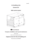
ATD-5933
RECHARGEABLE 12/24 VOLT 22 AMP/HOUR JUMP START
OWNERS MANUAL
•1700peakamps/700crankingampsofstartingpowerfor24V,3400peakamps/1400crankingampsfor12V.
•Startscars,trucks,RV’sandboatswithouttheneedofanothervehicleorACpowercords.
•12VDCsocketwithoverloadprotectionprovidespowerforany12Vappliance.
•Providesupto50Ͳhoursofdcpowerwhenusedwith12VDCappliances.
•Allows12VDCappliancestobeusedinremotesitesand/orinemergencieswhencommercialpowerisnotavailable.
•SolidͲstate,automaticoperationandcircuitprotection.
•Requiresnomaintenanceforoptimumoperation.
•Sealed,maintenanceͲfree,heavyͲdutybatteryissafetouseandtransport.
•Canbestoredinanypositionwithoutriskingacidleakage.
•HeavyͲduty#2industrialtypeweldingcablescancarrymoreamperagethansimilarunits.
•Easytoreadcolorcodedbatterymeter.
•DCpowercordallowsrechargingfrom12VDCsocket.
•MoldedhighͲimpactcaseistoughanddurable.
•BuiltͲin120VACrechargingcircuitrywithanautomaticcutͲofftopreventovercharging.
•Hasexternal120VAC1000mArechargingcircuitry.
MadeinChinatoATDSpecifications
Visitusatwww.atdtools.com
CaliforniaProp65WARNING:
BatteriescontainleadandotherchemicalsknowntotheStateofCaliforniatocausecancer,birthdefectsandother
reproductiveharm.Washhandsafterhandling.
GeneralSafetyWarnings:
WARNING:Theinstructionsandwarningscontainedinthismanualshouldbereadandunderstoodbeforeusing
oroperatingthistool.Donotallowanyonetouseoroperatethistooluntiltheyhavereadthismanualandhave
developedathoroughunderstandingofhowthistoolworks.Failuretoobserveanyofthefollowinginstructionscould
resultinseverepersonalinjurytotooluserandbystanders,orcausedamagetothetoolandproperty.Keepthismanual
forfuturereference.
Note:Thewarningsandcautionsdiscussedinthisinstructionmanualcannotcoverallpossibleconditionsand
situationsthatmayoccur.Itmustbeunderstoodbytheoperatorthatcommonsenseandcautionarefactorswhich
cannotbebuiltintothisproduct,butmustbesuppliedbytheoperator.
WARNING:Usesafetyequipment.Usersandbystandersshouldusesafetygogglesorsafetyglasseswithside
shieldswhichcomplywithcurrentnationalstandards,orwhenneeded,afaceshield.UseanANSIapproveddustmaskor
respiratorwhenworkingaroundmetal,wood,andchemicaldustsandmists.Thisappliestoallpersonsintheworkarea.
AlsousenonͲskidsafetyshoes,hardhat,gloves,dustcollectionsystems,andhearingprotectionwhenappropriate.
WARNING:Keepbystandersandchildrenoutoftheworkareawhileoperatingthistool.
WARNING:Alwayskeepyourworkareaclean,uncluttered,andwelllit.Clutteredordarkareasinviteaccidents
andinjuries.DONOTworkonfloorsurfacesthatareslippery.
WARNING:Donotoperatethistoolifyouaretiredorundertheinfluenceofalcohol,drugs,ormedicationsthat
couldaffectyourabilitytousethetoolproperly.
WARNING:Dressproperly.Donotwearlooseclothingorjeweleryastheycanbecaughtinmovingparts.Wear
restrictivehaircoveringtocontainlonghair.
WARNING:Donotreachoveroracrossrunningmachines.Keepproperfootingandbalanceatalltimes.NonͲ
skidfootwearisrecommendedwhenworking.
LeadAcidBatterySafetyWarnings:
WARNING:WORKINGAROUNDLEADͲACIDBATTERIESMAYBEDANGEROUS.
x
x
x
LeadͲacidbatteriesreleaseexplosivegasesduringnormaloperation,chargingandjumpstarting.
AllleadͲacidbatteries(car,truckandboat)producehydrogengaswhichmayviolentlyexplodeinthepresenceof
fireorsparks.Donotsmoke,usematchesoracigarettelighterwhilenearbatteries.OnlyworkwithleadͲacid
batteriesinawellͲventilatedarea.Donothandlethebatterywhilewearingvinylclothingbecausestatic
electricitysparksaregeneratedwhenvinylclothingisrubbed.
Toreduceriskofbatteryexplosion,followtheseinstructionsandthosepublishedbythebatterymanufacturer
andmanufacturerofanyequipmentyouintendtouseinthevicinityofthebattery.Reviewcautionarymarkings
ontheseproductsandonengine.
EYEPROTECTION:
x Userandbystandersshouldalwaysweareyeprotection,appropriateprotectiveclothingandothersafety
equipmentwhenworkingnearleadͲacidbatteries.DonottoucheyeswhileworkingonoraroundleadͲacid
batteries.
x IFSPLASHEDWITHBATTERYACID,IMMEDIATELYFLUSHAFFECTEDAREASUCHASFACEANDPARTICULARLY
THEEYESWITHCLEANWATER.Seekmedicalattentionandcontinueflushingfaceandeyesuntilmedicalhelp
arrives.
WORKINGINENGINECOMPARTMENT:
x Useextremecautionwhileworkingwithintheenginecompartment,becausemovingpartsmaycausesevere
injury.Readandfollowallsafetyinstructionspublishedinthevehicle’sOwner’sManual.
GENERALPRECAUTIONS/PERSONALPRECAUTIONS:
x NeverworkalonewithleadͲacidbatteries.Makesurethatsomeoneisaroundtogiveassistanceifyouneed
help.
x Wearcompleteeyeprotectionandclothingprotection.Avoidtouchingeyeswhileworkingnearbattery.
x Incaseofbatteryacidcontactwitheyes,skinorclothing,alwayshavesoapandwaternearyourworkarea.
x Removejewelerysuchasrings,bracelets,necklacesandwatcheswhenworkingaroundabattery.AleadͲacid
batterycanproduceashortcircuitcurrent,whichcanmeltmetalsandresultinasevereburn.
x Donotdroptoolsorothermetalobjectsonornearthebatteryasasparkmayresult,ignitingexplosivegases.
x Neverjumpstartorattempttorechargeafrozenbattery.
ElectricalSafetyWarnings:
WARNING:Readallsafetywarningsandinstructions.Failuretofollowallwarningsandinstructionsmayresult
inelectricshock,fireand/orseriousinjuryordeath.
WARNING:Toreducetheriskofelectricshock,DONOTuseindampconditions,onwetsurfaces,orexposeto
rain.Donotpluginthisjumpstartoroperateitwithwethandsorwhilestandinginwater.
WARNING:Neverusethecordsorcablesforcarrying,pullingorunpluggingyourjumpstart.Graspplugandpull
todisconnectchargerfromoutlet.Keepcordawayfromheat,oil,sharpedgesormovingparts.Replacedamagedcords
immediately.
WARNING:Alwaysremovethechargerfromtheelectricoutletwhenmakingadjustments,changingparts,
cleaningorworkingonthetool.
WARNING:Careshouldbetakentoarrangethecordsandcablessotheywillnotbesteppedon,trippedover,or
otherwisesubjectedtodamageorstress.
WARNING:Neverattempttopluginoroperateequipmentwithdefectiveordamagedwires,chargercordor
chargercordplug.Haveanydefectiveordamagedpartsreplacedimmediatelybyqualifiedpersonnel.
WARNING:Avoidbodycontactwithelectricallygroundedsurfaces.Thereisanincreasedriskofelectricshockif
yourbodyisgrounded.
WARNING:IftheworkareaisnotequippedwithapermanentlyinstalledGroundFaultCircuitInterrupteroutlet
(GFCI),useaplugͲinGFCIbetweenthechargingcordandthepowerreceptacle.
ATDͲ5933SpecificWarnings:
WARNING: LeadͲacidbatteriesgeneratehydrogengasduringnormaloperation.Moregasisgeneratedwhenthe
batteryischarging.Hydrogengasis:
1.Explosive
2.Poisonoustobreathe
3.Highlyflammable
WARNING: Toavoidpossibledamagethatmayshortentheunitsworkinglife,protectthisunitfromdirect
sunlight,directheat,and/ormoisture.
WARNING: Thissystemisdesignedtobeusedonlyonvehiclesorboatswith12Ͳvoltelectricalsystems.
WARNING: Thissystemisnotdesignedtobeusedasareplacementforavehiclebattery.
WARNING: Toavoidanexplosionand/orthepossibilityofbeingsplashedwithbatteryacid:
•Neverallowtheredandblackclampstotoucheachotherorforbothtotouchthesamemetalobjectoranyelectrically
conductivematerialforthatmatter.
•OnlyattempttojumpstartavehicleorboatinawellͲventilatedarea.
•Alwaysconnectthered(+)clamptothepositive(+)batteryterminalfirst.
•Donotconnecttheblack(Ͳ)clamptothenegative(Ͳ)batteryterminal.
•Connecttheblack(Ͳ)clamptoanonͲmovingmetalpartontheenginenottothenegative(Ͳ)batteryterminal.
INTRODUCTION
Your power pack unit is designed as a compact, durable and portable jump start system for 12 and 24 volt DC vehicles
and boats. This self contained system will start most vehicles and boats without the need for a host vehicle or 120V AC
power supply. This system can also be used as a safe, portable source of 12V DC electric power in remote locations
and/or in emergencies.
The power pack unit has an easy to read, color coded battery meter that indicates charge level. A 12V DC socket is
provided for use with appliances that would operate from a vehicles cigarette lighter or 12V DC socket. This allows
maximum portability and utility when your power pack unit is used in remote locations.
For maximum convenience, your power pack unit can be recharged from a 120V AC power source. The built in
ery
500mA recharger/converter has an automa c cut off that prevents over charging t
A covered 12V DC socket
120V AC power recharging cord. The red light e
ng diode (led) illuminates when the system is recharging.
Note: on/off switch only controls power to the 2 battery clamps. We suggest you keep this switch in the
"off" position for all operations other than jump starting a car.
RECOMMENDATIONS FOR GETTING THE MOST FROM YOUR NEW POWER PACK UNIT
RECHARGING:
1. For maximum battery life, we recommend that your power pack unit be kept fully charged at all times. If the battery is
allowed to remain in a discharged state, battery life will be shortened. Table 1 shows the relationship of the frequency of
use between recharging and the expected number of charge/recharge cycles.
TABLE I. BATTERY LIFE
NUMBER OF JUMP STARTS
BETWEEN RECHARGING
1
5
10
DISCHARGE AND RECHARGE
CYCLES
1000+
700+
500+
2. The time required to fully recharge your power booster after jump starting an engine is a function of how many jump
starts are performed between recharging sessions. Table 2 shows the approximate recharging times you can expect.
Table II. RECHARGING TIMES vs. JUMP STARTS
Number Of
Jump Starts
1
2
3
Recharging Time
(In Hours)
8
16
24
Number Of
Jump Starts
4
5
6
Recharging Time
(In Hours)
32
40
48
3. Check the charge in your power pack unit often by depressing the red push button switch. The meter will show the
battery charge.
120V AC CHARGING:
Plug the 120V AC/12V DC charging adapter into a wall outlet and into the receptacle on your new power pack unit.
Charge this device for at least 4 hours or
l the meter shows a full (14- to 15-V DC) charge when the red push button switch
is depressed. The recharging converter circuit unit has an automa cut- circuit so the internal
ery cannot be
ry from 120V AC follow these steps:
overcharged. To recharge your power pack unit
1. Place the 12V/24V switchable switch in the 12V position for recharging the battery.
2. Pull the plug cover from the round receptacle on the front of the power pack unit.
3. The external charger furnished with your power pack has a standard 120V AC male plug at one end, and a cigarette style
plug at the other end. Plug the 120V AC plug into a 120V AC wall outlet and the cigarette style plug into the round
receptacle on the front of the power pack unit.
4.
to charge un l the voltmeter indicates full capacity in green area when the test bu
is pressed.
Important: do not stop charging before the meter indicates full capacity in green area.
Att his point, once the charger is disconnected, the voltage will slowly
le back to read 100%. This is quite normal and
ery is atf ull capacity. Note: to fully charge a
could take up to 72 hours, depending upon the
indicates thatt he
c
itely as the internal PCB has an au
state of discharge. The unit can remain plugged into the power socketi n
"
charging circuit" which will not allow an overcharge
on or damage to the
ery.
12V DC CHARGING:
Your new power pack uniti s equipped with a receptacle that will allow you to re-charge this system from the 12V DC
socketi n your vehicle or boat.
ed use oft he 12V
Note: We recommend that you use the 12V DC recharging procedure only when necessary, as c
DC recharging procedure may shorten the system's life. To use the 12V DC recharging system:
1. Insertt he power cord with the 12V DC plug into the 12V DC receptacle on your vehicle or boat.
2. Insertt he plug att he other end oft his power cord into the receptacle on the side of your power booster.
the meter shows a full (14- to 15-V DC) charge when the red rocker switch
Charge this device for at least 4 hours o
is depressed. Unlike the AC charging circuit, there is NO FLOATING CHARGE circuit on the DC charging outlet. It is HIGHLY
recommended that DC charging only be used in emergency cases.
OPERATION
To use your power pack unit as a 12V DC power source:
1.
up the cover of the 12V DC receptacle on the side of your jump pack.
2. Insert the 12V DC plug from the appliance into the 12V DC receptacle.
in the ͞Žī” posi on.
Note: on/oī switch can be
Table III will give you an idea of what oper
on me to expect when
ng from a fully charged system:
Table III. - POWER PACK AS A 12V DC POWER SOURCE
Appliance Type
Fluorescent Lights, Cell Phones
Radios, Fans, Depth Finders
Camcorders, VCR's, Spotlights
Electric Tools, Bilge Pumps
Electric Coolers
Air Compressors, Car Vacuums
mated
Power
on
(In
)
4
9
15
24
48
80
mated Usage
Times (In Hours)
30
21
12
7
3
1.5
Table IV will give you an idea of what oper on me you can expect when star ng from a fully charged system. When
using your power pack unit as a 120 v ac power source with a power inverter:
Table IV. - POWER PACK AS A 12V DC POWER SOURCE
WITH POWER INVERTER
Appliance Type
Spotlights, Sump Pumps & VCR's
Faxes, TV's, Small Appliances
Computers, Printers
Medium Power Tools, Blenders
mated
Power
on
)
(In
100
150
200
250
mated Usage
Times (In Hours)
1.5
1
0.75
0.05
JUMP STARTING:
For optimum performance, when using your power pack unit to jump start a vehicle or boat, please read and
Follow these step by step instructions:
1. Switch the engine of the vehicle or boat to be jump started to “off”.
2. Connect the red (+) “alligator” clamp to the red (+) positive battery terminal.
3. Connect the black ( ) “alligator” clamp to a non moving metal part of the engine, not to the ( ) negative battery
terminal.
4. Turn power pack unit switch to “12V” or “24V” setting, based on the vehicle you are starting.
5. Wait a minute or two to let the vehicle battery charge
6. Try to start the vehicle but do not try for more than 5 to 6 seconds.
7. If the vehicle or boat engine does not start, wait at least 3 minutes before trying again.
*under no circumstances allow the red and black clamps to touch each other or a common conductor*
Once the engine is running, first disconnect the black ( ) clamp and return this cable to its stored position on the power
pack unit, then disconnect the red (+) clamp and return this cable to its stored position on the power pack unit. As soon
as possible, connect your power pack unit system to 120 vac and recharge.
BATTERY REPLACEMENT
FIGURE 1. Rear view of the power pack unit showing the battery compartment
1. Unscrew and remove the Phillips head screws that hold the rear cover in place on the back of your power pack unit.
2. Lift off the cover plate to expose the battery compartment.
3. Lift the battery out of the battery compartment.
4. Detach the #4 jumper cables and the red and black recharging wires from the battery terminals.
5. Ensure thatt he replacement
ery came out.
just as the old
ery is oriented with the
ve on the right side and the
6. Connectt he red #4 jumper cable and red recharging wire to the
ve (+)
then connectt he black #4 jumper cable and recharging wire to the nega
(-)
and ghten.
conne
7. Taking care nott o damage the circuit board, slide the new
8. Replace the
on the le side,
terminal (also marked with red),
terminal. Double check all
ery in
ery compartment cover and secure in place with the Phillips head screws.
SPECIFICATIONS
ITEM # . . . . . . . …. . . . . . . . . . . . . . . . . . ATD-5933
VOLTAGE . . . . . . . . . . . . . . . . . . . . . . . . 12/24V DC SWITCHABLE
BOOST POWER . . . . . . . . . . . . . . . . . . . 700 CRANKING AMPS FOR 24V, 1400 CRANKING AMPS FOR 12V.
PEAK AMPS… …...…….. . . .. . . . . . . . . . .12V – 3400 AMPS, 24V - 1700 AMPS
BATTERY TYPE . . . . . . . . . . . . . . . . . . . SEALED, LEAD- ACID, RECHARGEABLE, MAINTENANCE-FREE, 12V DC, 22-AMP-HOURS
BOOSTER CABLES . . . . . . . . . . . . . . . . . 84”, #2 GAUGE WELDING CABLES WITH 1000 AMP "ALLIGATOR" CLAMPS
DIMENSIONS …. . . . . . . . . . . . . . . . . . . 15.75” x 14.56” x 7.48” (40 x 37 x 19 CM)
ITEM#
1
2
3
4
5
6
7
8
9
10
11
12
ORDERING PART# PART DESCRIPTION
FIXING BOARD, ON/OFF SWITCH
PRT5928-01
PRT5928-02
TEST SWITCH
PRT5932-03
KNOB, ON/OFF SWITCH
PRT5928-04
COVER, CIGARETTE
PRT5928-05
VOLTMETER
PRT5928-06
FRONT PANEL
PRT5928-07
FIXING BOARD, VOLTMETER
PRT5928-08
CIGARETTE LIGHTER SOCKET (INNER)
PRT5932-09
ON/OFF SWITCH
PRT5932-10
CLAMP, RED & BLACK WITH 2GA CABLE
PRT5928-11
CASE
ATD5904
BATTERY, 12V/22AH (x2)
ITEM#
13
15
16
17
18
19
20
21
22
23
24
N/S
ORDERING PART#
PRT5932-13
PRT5932-15
PRT5928-14
PRT5933-17
PRT5932-18
PRT5932-10
PRT5928-16
PRT5932-21
PRT5928-18-19
PRT5928-18-19
PRT5933-24
PRT5933-25
Made in China to ATD Speci ca ons
Visit us at www.atdtools.com
PART DESCRIPTION
FIXING BOARD, CHARGER
PCB
SCREW
BACK COVER
STICKER, BATTERY
CLAMP, RED & BLACK WITH 2GA CABLE
SCREW
RUBBER BASE
AC AND DC CHARGING CORDS
AC AND DC CHARGING CORDS
OVERLOAD PROTECTOR, 15A
SWITCH COVER