1
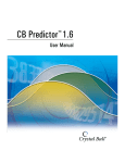
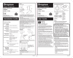
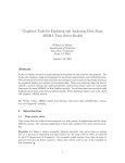
IN
S 6
M TAL 303
AN LA
UA TIO
L N
SAFETY INSTRUCTIONS
ZONED COMFORT CONTROL SYSTEM
Read this Installation Manual before beginning installation of the Aprilaire Zoned Comfort Control System.
For questions call Research Products Corporation at (800) 334-6011.
WARNING
CAUTION
1. 120 Volts may cause serious injury from
electrical shock. Sudden operation may cause
serious injury from moving parts. Leave power
disconnected until installation is complete.
2. Sharp edges may cause serious injury from
cuts. Use care when making duct openings and
handling ductwork.
3. The Aprilaire Zoned Comfort Control System is
designed for indoor use only. Do not expose
any component of the zone control system to
moisture. Do not mount any Aprilaire Zoned
Comfort Control equipment where it may be
accessible to children.
1. Installation must be done in accordance with
all applicable codes.
2. Installer should touch a grounded metal object
before handling the Aprilaire control panel to
avoid potential loss of internal computer
programs due to static discharge.
3. A zoned comfort control system may not
control temperature properly unless the
heating and cooling system is properly sized
and balanced.
4. Insufficient air flow or excessive temperatures
through the heating and cooling system could
result in equipment damage. Refer to the
manufacturer’s recommendations for minimum
safe airflow and temperature requirements.
5. Excessive pressure across a bypass
evaporative type humidifier may cause high air
velocity in the humidifier, resulting in water
being blown into the ductwork. Refer to Design
Guide for humidifier installation instructions.
6. Install an outdoor thermostat to prevent nonseasonal equipment starts if using auto
changeover thermostats.
7. Do not mount the control panel on any part of
the heating/cooling equipment or ductwork.
8. Do not install control panel where
temperatures exceed 158°F (70°C).
INSTALLATION
CAUTION: Installer must touch a
grounded metal object before
handling the Aprilaire Zoned
Comfort Control panel to avoid
potential loss of programs due to
static discharge.
MOUNTING HOLE
2 PLACES
ENCLOSURE BASE
CONTROL BOARD
MOUNTING HOLE
2 PLACES
1. MOUNT THE CONTROL PANEL
Four holes are provided on the back of the
unit for mounting. (See Figure 1)
• Mount indoors using #8 or #10 screws (field
supplied).
• Mount in location where the temperature will
not exceed 158°F and will not drop below
freezing (32°F).
• Do not mount on foundation walls, or on the
HVAC equipment or ductwork. These
locations can cause the enclosure to become
cooler than the surrounding air, which can
cause moisture to condense on the
enclosure.
“THROUGH-THE-WALL”
WIRING HOLE,
2 PLACES
E-HEA
ON T
OFF
E-HEA
ON T
OFF
#8 SCREWS (Field Supplied)
ENCLOSURE
COVER
FIGURE 1
2. MOUNT THE 8052 PLENUM TEMPERATURE SENSOR (provided)
IMPORTANT: Do not mount the sensor in direct line-of-sight of the heat exchanger,
cooling coils, or UV lights as they may cause the sensor to report false temperature
readings.
• Locate the sensor in the supply trunk, after the heat exchanger and cooling coils and
before the zone dampers (shaded areas). (See Figure 2)
• Mount the 8052 Sensor according to Installation Instructions provided with the sensor.
• Wire the 8052 Sensor to the Plenum Sensor terminals on the zoned comfort control panel
before power is applied to control panel.
• Measure the resistance across the Plenum Sensor terminals (before power is applied to
the panel) and confirm that it roughly corresponds to the ambient temperature values
listed in the table below.
ZONED COMFORT CONTROL:
MOUNT PLENUM SENSOR IN
SHADED AREA
ZONE DAMPERS
Ambient Temperature (°F)
Resistance (kΩ)
30
40
50
60
70
80
90
100
7.8
7.2
6.6
6.0
5.4
4.8
4.2
3.6
UPFLOW
FURNACE
FIGURE 2
90-690
• NOTE: In order for the control panel to recognize a sensor, it must be wired to the panel before power is applied.
3. PROVIDE CONTROL SYSTEM POWER
Install a transformer, separate from the transformer provided for the HVAC equipment, to provide power for the control panel, thermostats and
dampers. The size of the transformer depends on the greatest number of dampers that will be energized at any given time. If more than 6
dampers could be powered at one time, install dedicated damper transformers and a Model 8028 Damper Power Distribution Panel. Use the table
below to size the added transformer(s). Aprilaire Flexible Link Dampers require 12 VA per damper. Multiply the number of dampers by 12 and
select a transformer that meets or exceeds this value.
The table below illustrates.
Highest Number of Powered Dampers
VA Required
Select Transformer
3 or Less
4
5
6
7 or More
36 VA or less
48 VA
60 VA
72 VA
No. of Dampers* 12
40 VA
50 VA
75 VA
75 VA
75 VA + 40 VA / 3 Dampers
4. SET UP THE CONTROL PANEL FOR THE APPLICATION
• Z1 HC/Z1 HP is set according to the type of thermostat installed in Zone 1. If a heat/cool thermostat is used in Zone 1, place the pin jumper
block on the left two pins (Z1 HC). While set as Z1 HC, emergency heat can only be controlled with the on board E-HEAT switch. If a heat pump
thermostat is used in Zone 1, place the pin jumper block on the right two pins (Z1 HP). Using a heat pump thermostat in Zone 1 allows for
emergency heat control from the Zone 1 thermostat.
• GAS/ELECTRIC refers to the auxiliary heat source. If gas (or propane or oil) heat is to be used, place the pin jumper block on the left two pins
(GAS). This will allow the auxiliary heating equipment to control the fan operation through the use of a plenum switch. If electric heat is to be
used, place the pin jumper block on the right two pins (ELECTRIC).
• PURGE/NO PURGE determines whether the zone control panel or the equipment will control the fan purge. If set to PURGE, pin jumper block on
left two pins, the G terminal and any energized damper terminals will remain energized for a one-minute purge delay following the completion
of a cool call, regular heat call or an electric auxiliary heat call. If set to NO PURGE, pin jumper block on right two pins, the G terminal will deenergize immediately and any energized damper will remain energized for 3.5 minutes following the completion of a call. The NO PURGE
setting is designed for use with systems where the equipment has a built-in fan purge.
• HT-160/120: If using a plenum temperature sensor, this jumper controls the temperature at which the heating equipment will cut out to prevent
overheating. Set the high limit temperature that is appropriate for the equipment being used. For a high limit temperature of 160°F, place the pin
jumper block on the left two pins (HT-160). For a high limit temperature of 120°F, place the pin jumper block to the right two pins (120).
• CL-45/40: If using a plenum temperature sensor, this jumper controls the temperature at which the cooling equipment will cut out to prevent
freezing the indoor coil. For a low limit temperature of 45°F, place the pin jumper block on the left two pins (CL-45). For a low limit temperature
of 40°F, place the pin jumper block to the right two pins (40).
5.WIRE THE SYSTEM
Use standard 18 or 20 gauge thermostat wire, color coded wherever possible to simplify troubleshooting. The wiring diagram and the
THERMOSTAT SELECTION guide below are to be used to guide you through wiring the system.
6. THERMOSTAT SELECTION
Any single stage heating and cooling thermostat can be used in zones 1 through 3. Zone 1 (only) has the option of using a single stage heat pump
thermostat with an O terminal. Each thermostat must be capable of being turned off either through subbase or as a function of the thermostat.
Thermostat Requirements
Type: HEAT/COOL
(Zones 1–3)
Type: HEAT PUMP
(Zone 1 Only)
THERMOSTAT TERMINALS: R (24V-hot),
W (1st Stage Heat), Y (1st Stage Cool), G (Fan)
*See Note
THERMOSTAT TERMINALS: R (24V-hot),
O (Reversing Valve-cool), W (Auxiliary Heat),
Y (Compressor), G (Fan)
*See Note
RECOMMENDED THERMOSTATS:
Aprilaire 8344, 8363, or 8570
RECOMMENDED THERMOSTATS:
Aprilaire 8346, 8365, or 8570
*Note: The C terminal (24V-common) in each zone of the control panel can be used for 24 volt powered thermostats.
Terminal definitions (refer to thermostat manufacturer literature for matching terminals).
7. SEQUENCE OF OPERATION
Heat/Cool Thermostat Input Definitions: Heat = W, Cool =Y, Fan = G
Heat Pump Thermostat Input Definitions: Heat = Y, Cool = Y + O, Fan = G, Aux. Heat = Y + W, Emergency Heat = W
Fan Operation: A call for Fan from any zone will initiate the G equipment output terminal. The “NO” contact of the damper terminal for a zone not
calling for Fan also energizes, while the “NC” contact de-energizes.
Heating Operation: When a zone makes a call for heat, the B, Y and G output terminal will energize. The “NO” contact of the damper terminal for
any zone not calling for Heat also energizes, while the “NC” contact de-energizes. Following a 4-minute minimum on time, the Y terminal will deenergize when (1) all zones stop calling for heat, (2) the call has exceeded the heat/cool changeover time limit while a cooling call exists or (3)
the call is interrupted by the high limit setting. Any energized damper terminals remain energized for a one-minute purge (if set to PURGE) or a
3.5 minute purge (if set to NO PURGE). Should the same call exist for 20 minutes, the W terminal will also energize (if set to ELECTRIC) or the W
terminal will energize immediately after the Y and G terminals de-energize (if set to GAS). Following a 2-minute minimum on time (if set to GAS) or
immediately (if set to ELECTRIC), the W terminal will de-energize at the end of the heat call. When the W terminal is de-energized, it has a 4
minute minimum off time if set to GAS or no minimum off time if set to ELECTRIC. When the Y terminal is de-energized, a minimum off time delay
of 4 minutes must elapse before it can energize again. The B terminal remains energized until there is a call for cooling.
Cooling Operation: When a zone makes a call for Cooling, the O, Y and G terminals will energize. The “NO” contact of the damper terminals in
any zone not calling for Cooling also energizes, while the “NC” contact de-energizes. Following a 4-minute minimum on time, the Y terminal deenergizes when (1) all zones stop calling for cooling, (2) the call has exceeded the heat/cool changeover time limit while a heat call exists or (3)
the call is interrupted by the low limit setting. The G terminal and any energized damper terminals remain energized for a one-minute purge delay
if set to PURGE. If set to NO PURGE, the G terminal de-energizes immediately and any energized damper terminals remain energized for a 3.5minute purge delay. When the Y terminal is de-energized, a minimum off time of 4 minutes must elapse before it can be energized again. The O
terminal remains energized until there is a call for heat.
Emergency Heat Operation: Thermostat control of Emergency Heat only exists in Zone 1 when a Heat Pump thermostat is installed. In this case,
the first call for Emergency Heat sets the system to the Emergency Heat mode of operation. All subsequent calls for heat by other zones are
recognized as Emergency Heat calls until Zone 1 calls for normal heat or cooling.
If Zone 1 is configured as a heat/cool thermostat, Emergency heat can only be initiated by turning the E-HEAT switch on the zone control panel to
the ON position. When the E-HEAT switch is in the ON position, all calls for normal heating will be recognized as Emergency Heat calls. The
system will remain in Emergency Heat mode until the E-HEAT switch is moved to the OFF position, at which point calls for heat will once again be
answered with normal heating.
When a call for Emergency Heat is recognized, the Y terminal will de-energize (if energized) after a 4 minute minimum on time, after which the B
and W terminals (and G terminal if set to ELECTRIC) will energize. Following a 2-minute minimum on time (if set to GAS) or immediately (if set to
ELECTRIC), the W terminal will de-energize when (1) all zones stop calling for heat, (2) the call has exceeded the heat/cool changeover time limit
while a cooling call exists or (3) the call is interrupted by the high limit setting. Any energized damper terminals remain energized for a oneminute purge (if set to PURGE) or a 3.5 minute purge (if set to NO PURGE). When the W terminal is de-energized, it has a 4 minute minimum off
time if set to GAS or no minimum off time if set to ELECTRIC.
Heat/Cool Changeover: When a call for heat/cool exists and an opposing call is made from another zone, a changeover time limit of 20 minutes
begins at the time that the opposing call is made. If the original call is not satisfied within that 20-minute time period, the call will be interrupted,
turning the equipment off and allowing for the normal fan purge cycle and minimum equipment off time. The opposing call will then be answered.
After 20 minutes, if the original call still exists, the opposing call will be interrupted and the original call can once again be recognized.
High/Low Limit Temperature: The high/low limit temperature settings are designed to prevent the heat exchanger from overheating or the
cooling coil from freezing. An 8052 Sensor mounted in the supply duct senses the delivered air temperature and interrupts the heating/cooling
equipment (depending on the Heat and Cool temperatures set on the control panel) before overheating/freezing occurs. When a heating/cooling
call is interrupted by the high/low temperature limit, the zone control panel turns the equipment off and energizes the G terminal (if not already
energized). Once the temperature drops/rises 10°F, the equipment is turned back on if the call for conditioning still exists.
COMP.
C
FIELD INSTALLED JUMPER
REQUIRED FOR SINGLE
TRANSFORMER SYSTEMS
R
C
W2
Y
W
24
VAC
REQUIRED
TRANSFORMER
40 VA
NC
NO
C
R
W
Y
G
E-HEAT
ON
OFF
ZONE 3
TSTAT
INPUT
S
8052
Sensor
40
CL-45
FUSE - 3A
PLENUM
SENSOR
ZONE 2
DAMPER
INPUTS
ZONE 1
DAMPER
INPUTS
ZONE 2
TSTAT
INPUTS
ZONE 1
TSTAT
INPUTS
NC
NO
C
R
W
Y
G
NC
NO
C
R
W
Y
G
O
ZONE 2
ZONE 1
DAMPER WIRING NOTE
THE MAXIMUM AMOUNT OF CURRENT THAT
CAN BE SWITCHED THROUGH THE ZONE
PANEL IS 3 AMPS. IF MORE THAN 6
DAMPERS COULD BE POWERED AT ONE
TIME, INSTALL DEDICATED DAMPER
TRANSFORMERS AND A MODEL 8028
DAMPER POWER DISTRIBUTION PANEL.
WIRE ACCORDING TO THE INSTRUCTIONS
PROVIDED WITH THE MODEL 8028.
120
HT-160
NO
PURGE
ELECTRIC
Z1 HP
NORMAL
FLASHING
PURGE
GAS
Z1 HC
SPARE FUSE
INPUT
S
DAMPER
ZONE 3
(TIME DELAY
OVERRIDE)
T.D.O.
B TERMINAL IS NOT A 24V
COMMON CONNECTION.
Sensor must be installed
prior to powering up the
control panel
ZONE 3
24V
AC
B
O
G
Y
W2
RC
RH
EQUIPMENT OUTPUTS
40 VA per 3 DAMPERS
75 VA
Aprilaire® MODEL 6303 CONTROL PANEL
SHOWN WITH TYPICAL SINGLE STAGE HEAT PUMP AND ONE STAGE OF SUPPLEMENT HEAT
(SEE DAMPER WIRING NOTE IF 7 OR MORE)
7 OR MORE
4 THRU 6
MAX # OF POWERED
DAMPERS
3 OR LESS
USE SEPARATE 24VAC TRANSFORMER - DO
NOT USE HVAC SYSTEM TRANSFORMER
120
VAC
TRANSFORMER
120
VAC
24
VAC
AUX.HEAT/
EMERG. HEAT
FAN
RELAY
LOW VOLTAGE
CONTROL ONLY
L2
G
DEFROST
AIR HANDLER
B
O
Y
REV
VALVE
HEAT
REV
VALVE
COOL
1ST
STG
COMP.
FAN
COOL
HEAT
24V (HOT)
24V (COMMON)
REV. VALVE - COOL
FAN
COMPRESSOR
AUXILIARY HEAT
24V (HOT)
24V (COMMON)
ZONE 1
DAMPER
ZONE 1 THERMOSTAT
R
X
W2
Y
G
O
B
L
FAN
ON
1ST
STAGE
EHEAT
COOL
HEAT
OFF
HEAT PUMP THERMOSTAT
(If Heat/Cool thermostat, wire same as Zone 2)
OPTIONAL
1ST
STAGE
COOL
FAN ON
1ST STAGE HEAT
X
R
G
Y
W
MUST NOT BE HEAT PUMP THERMOSTAT
ZONE 2 THERMOSTAT
RECOMMENDED HEAT/COOL THERMOSTATS
(ZONES 1-3)
Aprilaire® 8344: non-programmable
Aprilaire® 8363: 5/2 day programmable
Aprilaire® 8570: 7 day programmable
REQUIRED
OUTDOOR UNIT
HEAT
LOW VOLTAGE CONTROL ONLY
HEAT
L1
RECOMMENDED HEAT PUMP THERMOSTATS
(ZONE 1 ONLY)
Aprilaire® 8346: non-programmable
Aprilaire® 8365: 5/2 day programmable
Aprilaire® 8570: 7 day programmable
OPTIONAL
OFF
P.O. BOX 1467 • MADISON, WI 53701-1467
Call toll-free 1-800/334-6011 • Fax 608/257-4357
COOL
CONTROL PANEL SET UP
1. Set Z1 HC/Z1 HP pin jumper block to the left two pins (Z1 HC) if installing a heat/cool thermostat in Zone 1.
Set the pin jumper block to the right two pins (Z1 HP) if installing a heat pump thermostat in Zone 1 for
thermostat control of Emergency Heat.
2. Set GAS/ELECTRIC pin jumper block to the right two pins (ELECTRIC) for most installations. This will
energize the Fan (G equipment terminal) with an Auxiliary or Emergency Heat Call (W). Set the pin jumper block
to the left two pins (GAS) if the auxiliary heat source is gas (or propane or oil).
3. Set the PURGE/NO PURGE pin jumper block to the left two pins (PURGE) if it is desired to have the zone
control panel control a 60 second purge cycle at the end of a cool call or electric heat call. Set the pin jumper
block to the right two pins (NO PURGE) if equipment control of the purge cycle is desired.
4. Set the HT-160/120 pin jumper block to the left two pins (Ht-160) to cut out the heating equipment at 160°F to
prevent overheating. Set the HT-160/120 pin jumper block to the right two pins (Ht-120) to cut out the heating
equipment at 120°F.
5. Set the CL-45/40 pin jumper block to the left two pins (CL-45) to cut out cooling equipment at 45°F to prevent
freezing the indoor cooling coil. Set the pin jumper block to the right two pins (CL-40) to cut out cooling
equipment at 40°F.
6. Ensure that the E-HEAT switch, in the lower left hand corner of the control panel, is in the off position.
7. Follow the Sequence of Operation to checkout the system after installation. Push and hold the TDO button to
speed up the internal clock and avoid built in time delays.
HEAT or COOL
6303 WIRING DIAGRAM
FAN AUTO
10006007 11.05
B2203179C
EHEAT
No Emergency Heat Call
FAN AUTO
Heat calls being satisfied with Emergency Heat
OFF
Won't stop calling
COOL
SYMPTOM
Normal Flashing LED not flashing
No Heat call or Cool call
TROUBLESHOOTING
CAUSE
No power to control panel - check power wiring
- TSTATS not operating properly. If Zone 1 is set up as a heat pump thermostat, it requires an O + Yfor cool call
and Y for a heat call.
- 4 minute minimum off time delay in effect - push TDO
- Missing jumper between equipment RH&RC - required for single transformer systems
- Equipment interrupt due to high/low temperature limit
- Heat/Cool Changeover limit in effect and an opposing call is being answered in another zone
Minimum on time delay in effect (2 minutes for heat, 4 minutes for cool)
- Heat Pump TSTAT installed in Zone 1: If Zone 1 is in Emergency Heat mode, all heat calls from other zones will be
satisfied with Emergency Heat until Zone 1 makes a compressor call (normal heat or cool call).
- Onboard E-HEAT switch is in the ON position and all calls for heat answered with Emergency Heat
- Zone 1 W terminal not energized or energized with Y terminal
- Onboard E-HEAT switch in the OFF position (Heat/Cool TSTATS installed in all zones)
©2005 Research Products Corporation
Printed in USA