1
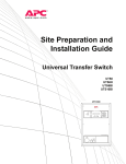
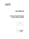
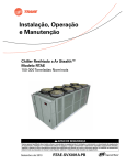
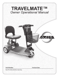
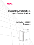
Operation Manual Universal Transfer Switch UTS6 UTS6H UTS6BI UTS10BI bu154a UTS10BI Introduction About this product The APC® by Schneider Electric Universal Transfer Switch (UTS) is a fully automatic transfer switch for use in optional standby systems in homes or small businesses. This unit provides safe, convenient power for up to ten circuits in the home or office. Power is derived from one or two independent backup sources. Backup sources being a generator, an uninterruptible power supply (UPS), a solar inverter, or another alternative energy source. When connected to home appliances, computers, or entertainment equipment the backup power sources provide power during utility power outages. When a UPS is used in the configuration, connected equipment (load), can be protected from utility brownouts, sags, surges, and power outages. The UPS provides continuous power from the internal battery until utility power returns to safe levels or the battery is fully discharged. The models supported by this manual vary in appearance and have some variation in function. UTS10BI bu154a Individual model functionality will be addressed in this manual. Protect your investment Fill out the Warranty Registration Card found in the documentation package, or register your purchase online at www.apc.com: • This will guarantee that the owner receive all of the information and special offers qualified for as the owner of this product. • This will confirm the owners right to maximum protection under the Warranty terms and conditions. • This will confirm yourself as the owner of the product in the event of fire, theft or loss. Operation Manual Universal Transfer Switch UTS6 UTS6H UTS6BI UTS10BI 1 Safety and Regulatory Information - save this information Read the Operation Manual before operating the UTS. Read, understand, and follow the Safety Precautions in this manual. Safety Precautions • Adhere to all national and local electrical codes when installing, configuring and operating the UTS. • Installation of the UTS must be performed by a qualified electrician. • Prior to installing the UTS have a qualified electrician check that the wiring in the home or office meets all local and national electrical codes. • This unit must be connected to a properly grounded utility power source. • Do not install or operate this unit near a source of water or in an environment where the relative humidity could exceed 95% (non-condensing). • DO NOT operate a generator inside a building. Operating a generator inside a building can cause death by asphyxiation. • DO NOT allow the total load connected to the UTS to exceed the limits listed in the Specifications section of the Site Preparation and Installation Guide. • There are no user serviceable components in this unit. Removing the cover from this unit by unqualified persons can present a shock hazard and may void the warranty. • Periodically inspect all power cords to ensure: – secure connections – proper routing to ensure cords are not pinched, frayed, or stepped on • If the UTS is damaged, disconnect the main circuit breaker and contact APC at www.apc.com. Warning: Stop using the unit immediately if any of the following conditions arise. •Conduit or receptacles have been damaged •Objects have fallen into the unit •Liquid has spilled into the unit •The unit has been exposed to rain •The unit has been dropped or damaged in any way •The unit does not operate properly Contact APC at www.apc.com, to arrange service for the unit. 2 Operation Manual Universal Transfer Switch UTS6 UTS6H UTS6BI UTS10BI UTS Configurable Features Feature Description Uninterruptible Power Supply • provides UPS backup for uninterrupted operation • provides backup power until the generator comes on line Adaptive Load Management (ALM) Provides automatic shut off (referred to as load shedding), of select circuits during blackout conditions • prevents power surges and overload conditions from stalling a generator, or tripping circuits • increases generator efficiency by 20% or more during prolonged power outages • automatically reconnects loads once the overload conditions have been corrected Load Transfer Provides automatic transfer of select loads between a generator and a UPS • minimizing power interruptions due to overload conditions • maximizing power availability Time Management & Load Shedding Time management feature sets maximum and minimum times for ALM to run Refer to the Configuration and Setup section in this manual for detailed functionality Voltage Sensitivity Settings determine how the UTS reacts to momentary power fluctuations MEDIUM - factory default LOW - useful when frequent, small power fluctuations DO NOT require UTS intervention HIGH - recommended ONLY for loads that are very sensitive to small, brief power fluctuations Security Mode also referred to as vacation mode When security mode is set to ON, the UTS automatically cycles power to circuits at a rate of two hours on and two hours off Recommended for use on strategic light circuits during vacations Bypass Mode During bypass mode operation all circuits utilize utility power ONLY • Backup power sources are not utilized regardless of the quality or condition of utility power • Overload protection remains available during bypass mode operation Liquid Crystal Display (LCD) • During initial setup and configuration the LCD displays the particular setting or value that is to be entered or changed • During regular operation the LCD is used with various LED indicators and push buttons providing UTS status messages, warnings • During regular operation the LCD is used with various LED indicators and push buttons to perform required actions Automatic Start/Stop Operation Semiautomatic operation: The UTS automatically switches to generator power once the generator has been connected and turned on. Fully automatic, compatible, remote controlled, auto stop/start generators require: • APC UTS Generator Hardwiring Interface Kit • APC UTS Automatic Remote Start/Stop Kit For ordering details contact APC through the Web site, www.apc.com. Operation Manual Universal Transfer Switch UTS6 UTS6H UTS6BI UTS10BI 3 UTS Controls and Indicators bu163a The UTS controls and indicators are located on the front of the UTS. Control or Indicator Description LCD • Displays two lines with 20 characters per line • Displays UTS status, warnings, general information • Displays the value or setting that is being entered or changed during configuration and setup System Status button Cycles the UTS through the default or selected system status options System Setup button Used to configure the UTS system options Circuit Status button Cycles the UTS through the circuits displaying the status of each on the LCD Circuit Setup button Used to configure the UTS individual circuit options Down/Up arrow buttons Used to scroll through steps for configuration and to scroll between status and informational displays Source LEDs Utility Generator UPS • Solid green LED illumination indicates that the power source is ON and is functioning normally • No LED illumination indicates that the power source is OFF or is outside specified limits • A flashing green LED indicates that a fault condition exists for that power source, and should be corrected Circuit LEDs The number of circuit LEDs varies dependent on the model of UTS • Red LED illumination indicates that the UTS circuit is receiving power from one of the power sources • No illumination indicates that circuit is receiving no power • A flashing red LED indicates that a fault condition exists and should be corrected 4 Operation Manual Universal Transfer Switch UTS6 UTS6H UTS6BI UTS10BI UTS circuit LED configurations UTS6BI Circuit UTS6/UTS6H Circuit 2 1 3 120 V 5 1 4 3 6 5 120 V circuits ONLY 120 V 240 V UTS10BI Circuit 2 1 4 3 6 5 Together, circuits 5 and 6 form a dedicated 240 V circuit. DO NOT use these circuits as individual 120 V circuits. 2 4 120 V 8 7 9 6 240 V 10 Together, circuits 9 and 10 form a dedicated 240 V circuit. DO NOT use these circuits as individual 120 V circuits. UTS Power Connectors The power connectors are located on the front of the UTS. bu164a UTS10BI Generator Inlet • Generator inlet is hardwired. Connection must be in a remote, outdoor location. Refer to the Connect UTS to Backup Power Sources section in the Site Preparation and Installation Guide. • Refer to the Site Preparation and Installation Guide for specifications concerning the generator power cable. UPS Inlet IEC 320 connector for UPS power cable. Convenience Outlet • NEMA 5-15, 120 V convenience outlet for connecting a UPS or another selected load. • Convenience outlet utilizes utility power or generator power. • If any circuits are to be configured as uninterruptible, a UPS must be used as the Backup2 power source. The UPS input cord should plug into the convenience outlet to allow the UPS battery to charge while operating on generator power. Operation Manual Universal Transfer Switch UTS6 UTS6H UTS6BI UTS10BI 5 System Status Verification The UTS system status and the status of up to three power sources can be viewed by pressing the System Status button located on the front of the UTS. To navigate through the system status menus, press the System Status button after viewing the information on the LCD. LCD displays the input voltages from the UTILITY through the main load center for PHASE1 and PHASE2. LCD displays the SYSTEM LOAD (total power), that is being drawn through the UTS AND the power drawn by each phase - PH1 and PH2 This information provides verification that the phases are balanced. LCD displays the BACKUP1 source voltages for GEN PHASE1 and GEN PHASE2. The UTS6H is intended for use with a single phase, 120 V generator. GEN PHASE1 and GEN PHASE2 will display identical voltage measurements. LCD displays the BACKUP1 source power outputs for GEN PHASE1 and GEN PHASE2. For power measurements: phase1 will display the power outputs of circuits 1, 3, 5. Phase2 will display power outputs for circuits 2, 4, 6. LCD displays the UPS VOLTAGE and UPS LOAD for the BACKUP2 source (normally a UPS). LCD displays the MODEL# (model number), and SN# (serial number) of the UTS. LCD displays the FW VER (firmware version) installed in the UTS. LCD displays the MFG DATE (date of manufacture) for the UTS. 6 UTILITY PHASE1: 120V UTILITY PHASE2: 120V SYSTEM LOAD: 2400W PH1: 1050W PH2: 1350W GEN PHASE1: 117V GEN PHASE2: 118V GEN PHASE1: 480W GEN PHASE2: 750W UPS VOLTAGE: 120V UPS POWER: 200W MODEL#: UTS10BI SN#: JB06008004272 UTS FW VER: 1 UI FW VER: 1 MFG DATE: xx/xx/xxxx Operation Manual Universal Transfer Switch UTS6 UTS6H UTS6BI UTS10BI System Configuration and Setup Once the UTS has been installed and connected to utility power by a qualified electrician, the UTS is ready for configuration and setup. System setup Press the System Setup button located on the front of the UTS to enter system setup mode and to navigate through the system setup options. Use the down/up arrow buttons to navigate through the configuration options and to change values displayed on the LCD. Note: The settings and values selected will change immediately after an arrow button is pressed. The LCD will revert back to the starting display message after 30 seconds with no activity. Bypass Mode Use the up arrow key to select NO, indicating that bypass mode is disabled or YES, enabling bypass mode on the UTS. In bypass mode, all circuits are powered by the utility power source. Backup power sources are not used to power loads regardless of the status or quality of the primary utility power source. BYPASS LOAD.. NO Warning: Changing bypass mode settings while connected to utility power will cause all connected loads to be momentarily disconnected. When bypass mode is enabled, overload protection is provided. High and low voltage protection is not available when bypass mode is enabled. Load Shedding Use the down/up arrow keys to select ON, indicating that load shedding is enabled or OFF, to disable load shedding. The UTS provides intelligent load management, defined by APC as adaptive load management (ALM). LOAD SHEDDING ON/OFF: ON When a backup power source is nearing an overload condition, ALM intelligence sheds (drops) select loads and then reconnects the loads when adequate power becomes available. ALM selects the most suitable loads to drop and reconnect at any given time minimizing overall load disruption, and maximizing backup power capability. When load shedding is enabled (ALM is on), the average energy output of a backup power source can increase by 20% or more. This allows more loads to be connected without overloading or stalling a backup power source. When load shedding is disabled (ALM is off), overload conditions can occur causing a generator to stall, a circuit breaker to trip, or loads may experience severe low voltage conditions. Load Shedding must be enabled for each circuit to be set individually for specific maximum time off and minimum time on. Refer to Circuit Maximum Time Off and Minimum Time On section in this manual. Voltage Sensitivity Use the down/up arrow keys to select High, Medium, or Low voltage sensitivity. The voltage sensitivity level determines how the UTS reacts to voltage fluctuations. VOLTAGE SENSITIVITY: MEDIUM Medium voltage sensitivity setting is a suitable setting for most situations. High voltage sensitivity setting is recommended only for loads that are very sensitive to voltage fluctuations. Low voltage sensitivity setting is recommended for loads that can tolerate most power fluctuations. Operation Manual Universal Transfer Switch UTS6 UTS6H UTS6BI UTS10BI 7 Time Management Use the up arrow key to select On indicating that time management is enabled or Off to disable time management. Time management is used with load shedding to ensure loads receive adequate power over extended periods of time. TIME MANAGEMENT: ON Time Management must be enabled for each circuit to be set individually for specific maximum time off and minimum time on. Refer to Circuit Maximum Time Off and Minimum Time On section in this manual. Reset Energy Meter This feature allows the user to reset to zero, the total number of kilowatt hours used collectively by the circuits connected to the UTS. Refer to Circuit Configuration and Setup in this manual. RESET ENERGY METER: NO System Test Setting the System Test to YES initiates a system self-test to check UTS operation. Use the down/up arrow keys to initiate a system self-test. System Test does not function when the UTS is set up for a manual start generator. Refer to Generator Start Mode in this manual for details. SYSTEM TEST: NO Backup1 Source Type The factory default setting is GENERATOR. The generator inlet located on the front of the UTS provides connectivity for a backup power source. The system setup has three options for backup power: BACKUP1 SOURCE TYPE: GENERATOR • Generator • UPS • Other Use the down/up arrow keys to select the preferred backup power source. Use the down/up arrow keys to select the preferred backup power source. APC recommends the use of a generator for BACKUP1. Backup1 (Generator) Power Rating Use the down/up arrow keys to set the correct power rating for the backup power source connected to the UTS. GEN POWER RATING: 0-12000 WATTS There are three levels for rapid rating increment changes. Press and hold the down or up arrow key to adjust the power rating and to move through the three levels described here. To revert back to level 1 release the down arrow key then press and hold the down arrow key. Level 1 increases or decreases the rating by 5 Watts. Level 2 increases or decreases the rating by 10 Watts. Level 3 increases or decreases the rating by 100 Watts. Generator Surge Overload Time Use the down/up arrow keys to set the desired ALM response time. When power output exceeds the pre-set power rating for the Backup1 Source (see Generator Power Rating above), this feature determines the time it will take for ALM to respond and activate load shedding process. GEN SRGE OVRLD TIME: 0-600 SEC Low generator surge overload time settings decrease the possibility of a generator overload condition while increasing the possibility that ALM will activate load shedding. High generator surge overload time settings increase the possibility of a generator overload condition while decreasing the possibility the ALM will activate load shedding. Inverter generators must be set at 0 seconds. 8 Operation Manual Universal Transfer Switch UTS6 UTS6H UTS6BI UTS10BI Generator Start Mode For generators featuring manual start, use the MANUAL setting. Press the down or up arrow key to change to AUTO setting. A warning message appears on the LCD. Wait a few seconds and another message appears on the LCD asking for confirmation that the generator is located outdoors. Use the down or up arrow keys to select YES or NO. A UTS Hardwire Interface Kit for connecting the generator outside the house is available through your dealer or APC, www.apc.com. GEN START MODE: MANUAL GEN EXHAUST CAN KILL START GEN OUTDOORS.. CONFIRM GEN OUTDOORS: NO WARNING: Home generator backup systems should be installed by a qualified electrician. Locate the generator outside a building and at least 10 feet away from buildings, windows, and doors. Failure to follow this safety rule may result in illness or death from breathing carbon monoxide. The generator must have three to four feet of space around all sides and the top to ensure proper ventilation. Locate the generator on a dry, level surface protected from rain and excessive dust. Fuel for gas operated generators must be stored in approved containers, and in well ventilated conditions. Refer to the generator user documentation for additional safety precautions. For generators featuring automatic start, use the AUTO setting. The UTS has a remote automatic start/stop function for use with generators having the following features: • automatic start • automatic choke • remote start/stop capability Refer to the documentation in the Generator Automatic Start/Stop Kit for automatic generator configuration instructions. Backup2 Source Type The factory default setting is UPS. The backup2 power source inlet, located on the front of the UTS is labeled UPS Inlet as a UPS is the preferred backup2 power source. BACKUP2 SOURCE TYPE: UPS The system setup has three options for backup power: • Generator • UPS (recommended BACKUP2 power source) • Other Use the down/up arrow keys to select the preferred backup power source. NOTE: It is recommended that a UPS be used as BACKUP2 SOURCE TYPE. A UPS provides continuous battery backup power during utility brownouts, sags, surges, and power outages. Without the use of a UPS, fully automatic operation of the UTS cannot be guaranteed. If a UPS is not selected for the BACKUP2 power source be sure that the UNINTERRUPTIBLE option under Circuit Setup Option 2 is not selected. Operation Manual Universal Transfer Switch UTS6 UTS6H UTS6BI UTS10BI 9 UPS Power Rating Once the BACKUP2 SOURCE TYPE has been selected, that source type will appear in the power rating display message. Use the down/up arrow keys to set the correct power rating for the backup2 power source connected to the UTS. UPS POWER RATING: 0-1800 WATTS There are three levels for rapid rating increment changes. Press and hold the down or up arrow key to adjust the power rating and to move through the three levels described here. To revert back to level 1 release the down arrow key then press and hold the down arrow key. Level 1 increases or decreases the rating by 5 Watts. Level 2 increases or decreases the rating by 10 Watts. Level 3 increases or decreases the rating by 100 Watts. UPS Surge Overload Time Once the BACKUP2 SOURCE TYPE has been selected, that source type will appear in the surge overload time display message. Use the down/up arrow keys to set the desired ALM response time. UPS SRGE OVRLD TIME: 0-60 SEC When power output exceeds the pre-set power rating for the Backup21 Source (see UPS Power Rating above), this feature determines the time it will take for ALM to respond and activate load shedding process. Low UPS surge overload time settings decrease the possibility of a generator overload condition while increasing the possibility that ALM will activate load shedding. High UPS surge overload time settings increase the possibility of a generator overload condition while decreasing the possibility the ALM will activate load shedding. Reset to Factory Default Use the down/up arrow keys to select YES. This will reset all configurable parameters to the factory default settings. Selecting YES will also start the UTS Setup Wizard described in the Site Preparation and Installation Guide supplied with this unit. RESET TO DEFAULT: NO Circuit Status Verification The status of each circuit on the UTS can be viewed by pressing the Circuit Status button located on the front of the UTS. To navigate through the circuits, press the Circuit Status button after viewing the status of each circuit. CK1SRC (circuit1 source) indicates the power source (utility power), plus the status of circuit1: number of Amps, number of kWh, and number of Watts. CK1SRC: UTILITY AMP: 1 KWH: 2:35 WATTS: 120 Circuit Configuration and Setup Circuit setup Press the Circuit Setup button located on the front of the UTS to enter circuit setup mode and to navigate through the circuit setup options. Circuit setup begins with circuit 1 and proceeds through all of the configuration options for circuit 1 before moving on to circuit 2. The same is true for circuit 2, then circuit 3 and so on. Use the down/up arrow buttons to navigate through the configuration options and to change values displayed on the LCD. Note: The settings and values selected will change immediately after an arrow button is pressed. The LCD will revert back to the starting display message after 30 seconds with no activity. To configure a specific circuit, press the Circuit Status button until the display shows the desired circuit, then press the Circuit Setup button. The LCD will display the first setup option for the selected circuit. 10 Operation Manual Universal Transfer Switch UTS6 UTS6H UTS6BI UTS10BI Circuit setup options Setup Option 1-Circuit Load Type A UTS can be configured for many load types. These and other load types may be labeled on the building circuit breaker panel. LIGHTS GARAGE DOOR OPENER FURNACE (HOT AIR) FURNACE (HOT WATER) FREEZER AIR CONDITIONER NONE OTHER SUMP PUMP SPRINKLER SYSTEM SECURITY SYSTEM REFRIGERATOR WELL PUMP (or other motor driven device i.e. blower or exhaust fan) MICROWAVE OVEN Setup Option 2-Source The factory default setting for the backup power source is GEN (generator). Use the down/up arrow keys to establish the backup power source for a selected circuit. GEN-backup power source will be a connected generator. UNINTERRUPTIBLE-there is continuous backup power supplied by a UPS. Utility power flows into the UPS and from the UPS to the connected load. This provides power and protection for the load during any utility power fluctuation. NONE-there will be no backup power source available. EITHER-backup power source will be either a connected generator or a UPS. UPS-backup power source will be a connected UPS. Note: Backup power source availability varies for some circuits. The UPS and EITHER backup power source options are not available for: • circuit1 on all units • the designated 240 V circuits on the UTS6BI or the UTS10BI Delayable Circuits The factory default setting is NO. Setting a circuit to YES, enables the UTS to run ALM for the individual circuit selected. The UTS provides intelligent load management, defined by APC as adaptive load management (ALM). CKT1 DELAYABLE NO The Delayable Circuits setup option works in conjunction with Load Shedding and Time Management. The Delayable Circuits setup option requires that both Load Shedding and Time Management under System Setup, be set to ON. Once Load Shedding and Time Management have been enabled each circuit can be individually set to YES enabling the Delayable Circuits feature. • Load Shedding is used with time management to ensure loads receive adequate power over extended periods of time. When a backup power source is nearing an overload condition, ALM intelligence sheds (drops), select loads and then reconnects the loads when adequate power becomes available. ALM selects the most suitable loads to drop and reconnect at any given time minimizing overall load disruption, and maximizing backup power capability. • When load shedding is disabled (ALM is off), overload conditions can occur causing a generator to stall, a circuit breaker to trip, or loads may experience severe low voltage conditions. • Time Management is used with load shedding to ensure loads receive adequate power over extended periods of time. There are two time management settings, Maximum Off and Minimum On. These can be set for each circuit through Circuit Setup. When this feature is on, time management ensures that loads are not shed (power is not removed), for more than the set Maximum Off time. This feature also ensures that loads receive power for the Minimum On time set in circuit setup. Operation Manual Universal Transfer Switch UTS6 UTS6H UTS6BI UTS10BI 11 Circuit Maximum Time Off and Minimum Time On This setup option requires that Load Shedding and Time Management under System Setup, be set to ON. Once Load Shedding and Time Management have been enabled each circuit can be set individually for specific maximum time off and minimum time on. These settings will depend on the requirements of the load each circuit supports. Maximum Off controls the allowable time for a load to be without power, after being shed during ALM operation.This prevents overload conditions. Minimum On controls the amount of time a circuit must receive power before it is eligible to be shed to prevent an overload condition. It is recommended that a refrigerator should have a Minimum On setting of 45 minutes to ensure adequate cooling time of contents. CKT1 MAX TIME OFF: 1-60MIN CKT1 MIN TIME ON: 1-60MIN Circuit Security Mode The factory default setting is OFF. This setup option is intended specifically for use with a specified lighting circuits. Selecting YES, enables Circuit Security Mode. The UTS will automatically cycle power to the designated circuits for two hours on and two hours off. CKT1 SECURITY MODE: OFF Circuit Amp Rating Warning: This setup option should be configured by a qualified electrician during the initial setup and installation of the UTS. Adhere to all national and local electrical codes when setting the Amp ratings for the UTS circuits. Failure to comply with electrical codes could result in UTS malfunction and damage. The factory default setting is 15 Amps. The Amps for each circuit on the UTS should be set to match the Amp rating of the supporting circuit on the building circuit breaker panel. 12 CKT1 AMP RATING: 15 AMPS Operation Manual Universal Transfer Switch UTS6 UTS6H UTS6BI UTS10BI Troubleshooting Use this chart to solve minor UTS problems. Refer to www.apc.com for assistance with complex UTS problems. Problem and Possible Cause Solution Problem: While operating on utility power the UTS repeatedly drops some connected loads Cause: One or more circuits may be in Security Mode. Using the Circuit Setup button on the UTS, check to verify the status of Security Mode. Cause: The LCD displays a message indicating that one or more circuits may be experiencing an overload condition. Reduce the load on the affected circuits or have a qualified electrician upgrade the circuit amp capacity. Problem: While operating on backup power the UTS repeatedly drops some connected loads Cause: ALM may be enabled. • Disable ALM using the System Setup button. NOTE: When ALM is disabled overload conditions can occur causing a generator to stall, a circuit breaker to trip, or loads may experience severe low voltage conditions. Cause: The circuit may be incorrectly configured as delayable. Use the Circuit Setup button to navigate to CKT DELAYABLE screen for the circuit affected. Disable the circuit delayable option, (select NO). This disables ALM for that circuit. Repeat this process for all circuits affected. Cause: The circuit may be incorrectly configured for MAX OFF and MIN ON. Change the parameters for Maximum OFF and Minimum ON times, for circuits supporting loads being adversely affected by drops. Cause: The generator power rating is set too low. Refer to System Setup: Backup1 Power Rating in this manual. Problem: While operating on backup power the generator stalls, shuts down or the circuit breaker trips repeatedly Cause: The generator power rating is set too high causing an overload condition. Refer to System Setup: Backup1 Power Rating in this manual. Cause: The Generator Surge Overload Delay Time is set too high. Refer to System Setup: Generator Surge Overload Delay Time in this manual. Cause: ALM has been disabled causing an overload condition for the generator. Enable ALM. Refer to these sections in this manual. • System Setup: Load Shedding, and Time Management • Circuit Setup: Delayable Circuits Operation Manual Universal Transfer Switch UTS6 UTS6H UTS6BI UTS10BI 13 Problem and Possible Cause Solution Problem: While operating on backup power the UPS repeatedly experiences an overload condition causing the circuit breaker to trip Cause: The UPS power rating is set too high causing an overload condition. Refer to System Setup: Backup2 Power Rating in this manual. Cause: The UPS Surge Overload Delay Time is set too high. Refer to System Setup: UPS Surge Overload Delay Time in this manual. Cause: The UPS is experiencing a low battery condition. • The UPS batteries recharge during normal UPS operation. Refer to the UPS user manual or go to the APC Web site, www.apc.com. for battery recharge times. • The UPS batteries may need to be replaced. Refer to the UPS user manual or go to the APC Web site, www.apc.com for replacement battery information. Problem: The UPS operates on battery power while the generator is running Cause: The UPS is not receiving power. Check that the UPS is securely connected to the Convenience Outlet on the UTS. Cause: The Voltage Sensitivity for Backup2 Power Source is set incorrectly. • Refer to System Setup: Voltage Sensitivity in this manual. The sensitivity setting should be Medium or Low. Problem: The LCD displays the message CKTX FAULT CONDITION NO OUTPUT Cause: The circuit breaker may be tripped. • Reset the circuit breaker. • Check the current rating for the circuit. Refer to Circuit Setup: Circuit Amp Rating in this manual. NOTE: Properly configuring the Amp rating requires the services of a qualified electrician. Cause: The fuse for the circuit breaker may be blown. Replace the fuse, and reset the circuit breaker. NOTE: Replacing a fuse requires the services of a qualified electrician. Problem: The UPS does not supply power to Circuit1 Cause: The UPS is not connected to circuit1. 14 Circuit1 is intended for use with utility or generator power ONLY. Operation Manual Universal Transfer Switch UTS6 UTS6H UTS6BI UTS10BI Service If the unit requires service do not return it to the dealer. Follow these steps: 1. Review the problems discussed in Troubleshooting to eliminate common problems. 2. If the problem persists, contact APC Customer Support through the APC Web site, www.apc.com. – Note the model number of the unit, the serial number located on the front of the unit, and the date purchased. If you call APC Customer Support, a technician will ask you to describe the problem and attempt to solve it over the phone. If this is not possible, the technician will issue a Returned Material Authorization Number (RMA#). – If the unit is under warranty, repairs are free. – Procedures for servicing or returning products may vary internationally. Refer to the APC Web site for country specific instructions. 3. Pack the unit in its original packaging. If this is not available: – Pack the unit carefully to avoid damage in transit. Never use Styrofoam beads for packaging. – Damage sustained in transit is not covered under warranty. 4. Mark the RMA# on the outside of the package. 5. Return the unit by insured, prepaid carrier to the address given to you by Customer Support. APC Worldwide Customer Support Customer support for this or any other APC product is available at no charge in any of the following ways: • Refer to the APC Web site to access documents in the APC Knowledge Base and to submit customer support requests. – www.apc.com (Corporate Headquarters) Connect to localized APC Web sites for specific countries, each of which provides customer support information. – www.apc.com/support/ Global support searching APC Knowledge Base and using e-support. • Contact an APC Customer Support center by telephone or e-mail. Local, country-specific centers: go to www.apc.com/support/contact for information. Contact the APC representative or other distributor from whom you purchased your APC product for information on how to obtain local customer support. Regulatory Information Radio Frequency Warnings FCC Class B Compliance Notice This equipment has been tested and found to comply with the limits for a Class B digital device, pursuant to Part 15 of the FCC Rules. These limits are designed to provide reasonable protection against harmful interference in a residential installation. This equipment generates, uses and, can radiate radio frequency energy and if not installed and used in accordance with the instructions, may cause harmful interference to radio communications. However, there is no guarantee that interference will not occur in a particular installation. If this equipment does cause harmful interference to radio and television reception, which can be determined by turning the equipment off and on, the user is encouraged to try to correct the interference by one or more of the following measures. • • • • Reorient or relocate the receiving antenna. Increase the separation between the equipment and receiver. Connect the equipment into an outlet on a circuit different from that to which the receiver is connected. Consult the dealer or an experienced radio/TV technician for help. Operation Manual Universal Transfer Switch UTS6 UTS6H UTS6BI UTS10BI 15 Two-Year Warranty The limited warranty provided by American Power Conversion (APC®) in this statement of Limited Factory Warranty applies only to products you purchase for your commercial or industrial use in the ordinary course of your business. Terms of warranty APC warrants its products to be free from defects in materials and workmanship for a period of two years from the date of purchase. The obligation of APC under this warranty is limited to repairing or replacing, at its sole discretion, any such defective products. This warranty does not apply to equipment that has been damaged by accident, negligence or misapplication or has been altered or modified in any way. Repair or replacement of a defective product or part thereof does not extend the original warranty period. Any parts furnished under this warranty may be new or factoryremanufactured. Non-transferable warranty This warranty extends only to the original purchaser who must have properly registered the product. The product may be registered at the APC Web site, www.apc.com. Exclusions APC shall not be liable under the warranty if its testing and examination disclose that the alleged defect in the product does not exist or was caused by end user or any third person misuse, negligence, improper installation or testing. Further, APC shall not be liable under the warranty for unauthorized attempts to repair or modify wrong or inadequate electrical voltage or connection, inappropriate on-site operation conditions, corrosive atmosphere, repair, installation, start-up by non-APC designated personnel, a change in location or operating use, exposure to the elements, Acts of God, fire, theft, or installation contrary to APC recommendations or specifications or in any event if the APC serial number has been altered, defaced, or removed, or any other cause beyond the range of the intended use. THERE ARE NO WARRANTIES, EXPRESS OR IMPLIED, BY OPERATION OF LAW OR OTHERWISE, OF PRODUCTS SOLD, SERVICED OR FURNISHED UNDER THIS AGREEMENT OR IN CONNECTION HEREWITH. APC DISCLAIMS ALL IMPLIED WARRANTIES OF MERCHANTABILITY, SATISFACTION AND FITNESS FOR A PARTICULAR PURPOSE. APC EXPRESS WARRANTIES WILL NOT BE ENLARGED, DIMINISHED, OR AFFECTED BY AND NO OBLIGATION OR LIABILITY WILL ARISE OUT OF, APC RENDERING OF TECHNICAL OR OTHER ADVICE OR SERVICE IN CONNECTION WITH THE PRODUCTS. THE FOREGOING WARRANTIES AND REMEDIES ARE EXCLUSIVE AND IN LIEU OF ALL OTHER WARRANTIES AND REMEDIES. THE WARRANTIES SET FORTH ABOVE CONSTITUTE APC SOLE LIABILITY AND PURCHASER EXCLUSIVE REMEDY FOR ANY BREACH OF SUCH WARRANTIES. APC WARRANTIES EXTEND ONLY TO PURCHASER AND ARE NOT EXTENDED TO ANY THIRD PARTIES. IN NO EVENT SHALL APC, ITS OFFICERS, DIRECTORS, AFFILIATES OR EMPLOYEES BE LIABLE FOR ANY FORM OF INDIRECT, SPECIAL, CONSEQUENTIAL OR PUNITIVE DAMAGES, ARISING OUT OF THE USE, SERVICE OR INSTALLATION, OF THE PRODUCTS, WHETHER SUCH DAMAGES ARISE IN CONTRACT OR TORT, IRRESPECTIVE OF FAULT, NEGLIGENCE OR STRICT LIABILITY OR WHETHER APC HAS BEEN ADVISED IN ADVANCE OF THE POSSIBILITY OF SUCH DAMAGES. SPECIFICALLY, APC IS NOT LIABLE FOR ANY COSTS, SUCH AS LOST PROFITS OR REVENUE, LOSS OF EQUIPMENT, LOSS OF USE OF EQUIPMENT, LOSS OF SOFTWARE, LOSS OF DATA, COSTS OF SUBSTITUENTS, CLAIMS BY THIRD PARTIES, OR OTHERWISE. NO SALESMAN, EMPLOYEE OR AGENT OF APC IS AUTHORIZED TO ADD TO OR VARY THE TERMS OF THIS WARRANTY. WARRANTY TERMS MAY BE MODIFIED, IF AT ALL, ONLY IN WRITING SIGNED BY AN APC OFFICER AND LEGAL DEPARTMENT. Warranty claims Customers with warranty claims issues may access the APC customer support network through the Support page of the APC Web site, www.apc.com/ support. Select your country from the country selection pull-down menu. Open the Support tab at the top of the Web page to obtain contact information for customer support in your region. © 2010 APC by Schneider Electric. APC, the APC logo, Smart-UPS and Back-UPS are owned by Schneider Electric Industries S.A.S., American Power Conversion Corporation, or their affiliated companies. All other trademarks are property of their respective owners. 16 Operation Manual Universal Transfer Switch UTS6 UTS6H UTS6BI UTS10BI 990-2993C 4/2010