1
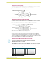
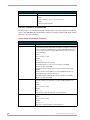
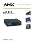
instruction manual
AXB-IRS4
IR/Serial Interface (4 Ports)
AXlink Bus Controllers
AMX Limited Warranty and Disclaimer
AMX Corporation warrants its products to be free of defects in material and workmanship under normal use for
three (3) years from the date of purchase from AMX Corporation, with the following exceptions:
•
Electroluminescent and LCD Control Panels are warranted for three (3) years, except for the display and touch
overlay components that are warranted for a period of one (1) year.
•
Disk drive mechanisms, pan/tilt heads, power supplies, MX Series products, and KC Series products are
warranted for a period of one (1) year.
•
Unless otherwise specified, OEM and custom products are warranted for a period of one (1) year.
•
Software is warranted for a period of ninety (90) days.
•
Batteries and incandescent lamps are not covered under the warranty.
This warranty extends only to products purchased directly from AMX Corporation or an Authorized AMX Dealer.
AMX Corporation is not liable for any damages caused by its products or for the failure of its products to perform.
This includes any lost profits, lost savings, incidental damages, or consequential damages. AMX Corporation is not
liable for any claim made by a third party or by an AMX Dealer for a third party.
This limitation of liability applies whether damages are sought, or a claim is made, under this warranty or as a tort
claim (including negligence and strict product liability), a contract claim, or any other claim. This limitation of
liability cannot be waived or amended by any person. This limitation of liability will be effective even if AMX
Corporation or an authorized representative of AMX Corporation has been advised of the possibility of any such
damages. This limitation of liability, however, will not apply to claims for personal injury.
Some states do not allow a limitation of how long an implied warranty last. Some states do not allow the limitation or
exclusion of incidental or consequential damages for consumer products. In such states, the limitation or exclusion of
the Limited Warranty may not apply. This Limited Warranty gives the owner specific legal rights. The owner may
also have other rights that vary from state to state. The owner is advised to consult applicable state laws for full
determination of rights.
EXCEPT AS EXPRESSLY SET FORTH IN THIS WARRANTY, AMX CORPORATION MAKES NO
OTHER WARRANTIES, EXPRESSED OR IMPLIED, INCLUDING ANY IMPLIED WARRANTIES OF
MERCHANTABILITY OR FITNESS FOR A PARTICULAR PURPOSE. AMX CORPORATION
EXPRESSLY DISCLAIMS ALL WARRANTIES NOT STATED IN THIS LIMITED WARRANTY. ANY
IMPLIED WARRANTIES THAT MAY BE IMPOSED BY LAW ARE LIMITED TO THE TERMS OF THIS
LIMITED WARRANTY.
Table of Contents
Table of Contents
Product Information .................................................................................................1
Specifications
.............................................................................................................. 1
Configuration and Installation .................................................................................3
Setting the Device DIP Switch........................................................................................... 3
Setting the Carrier/BAUD DIP switch ................................................................................ 3
Positions 1-4: Carrier signal enable/disable............................................................................. 4
Position 5: RS-232/PCTouch mode ......................................................................................... 4
Positions 6-8: Baud rate setting ............................................................................................... 4
Setting the Internal Jumpers (E1 and E2) for AXlink or
RS-232 Communication ................................................................................................. 5
Removing the circuit card......................................................................................................... 5
AXlink communication.............................................................................................................. 5
RS232 communication ............................................................................................................. 5
Wiring the AXB-IRS4......................................................................................................... 6
Wiring Guidelines ..................................................................................................................... 6
Preparing/connecting captive wires ......................................................................................... 6
Using AXlink for data and power.............................................................................................. 7
Using AXlink for data and a 12 VDC power supply.................................................................. 7
Using the AXlink-to-DB-9 connector cable for a PC system .................................................... 7
Using the AXlink-to-DB-25 connector cable for a PC system .................................................. 8
Connecting an IR device .......................................................................................................... 9
Connecting a serial device ....................................................................................................... 9
Replacing the Lithium Battery ........................................................................................... 9
Programming ..........................................................................................................11
Channel Setting Commands ........................................................................................... 11
Send Commands............................................................................................................. 11
RS-232 Protocol Commands........................................................................................... 14
RS-232 Protocol Commands (IR Output)............................................................................... 14
RS-232 Protocol Commands (Channel Pulse Time).............................................................. 15
RS-232 Protocol Commands (Carrier) ................................................................................... 15
RS-232 Protocol Commands (Miscellaneous) ...................................................................... 16
AXB-IRS4 IR/Serial Interface (4 Ports)
i
Table of Contents
ii
AXB-IRS4 IR/Serial Interface (4 Ports)
Product Information
Product Information
The AXB-IRS4 (FIG. 1) is an AXCESS bus device you can program to control up to four infrared
(IR) or serial-controlled audiovisual devices such as televisions and video cassette recorders. The
AXB-IRS4 can be controlled by an AMX AXCESS or AXCENT2 system, or independently with a
personal computer (PC).
The AXB-IRS4 can be programmed to control a wide variety of AV equipment. If you change the
IR or serial equipment in your system, you can easily reprogram the AXB-IRS4 with new control
commands. This flexibility allows you to upgrade your system as advances are made in AV
equipment.
Specifications
AXB-IRS4 Specifications
Control
Controls up to four IR or serial devices
Memory
28K bytes (total); stores up to 200 control commands in each port.
Power requirement
12 VDC
Power consumption
125 mA
Supported baud rates
300, 600, 1,200, 2,400, 4,800, 9,600, 19,200
Front panel components
AXlink LED
The AXlink LED blinks when there is AXlink or RS-232 communication activity
or a memory error. If an AMX system controls the AXB-IRS4, the green AXlink
LED indicates the following power and data activity, or memory errors:
• One blink per second: Power is active and the AXlink is functional.
• Full on: Power is active and AXlink communication is not functional.
• Fast blink: There is a memory error. A memory error can be caused by a
power-deficient battery. Follow the instructions in the Replacing the Lithium
Battery section on page 9. If the error continues, contact AMX technical
support for assistance.
• If a PC system controls the AXB-IRS4, the green AXlink LED blinks when
RS-232 data is received or transmitted.
DEVICE DIP switch
8-position DIP switch that sets the AXB-IRS4's device number so that the Central Controller sends the proper control commands to the correct device. See
the Setting the Device DIP Switch section on page 3 for details.
CARRIER/BAUD DIP switch 8-position DIP switch that sets the carrier/No Carrier (NC) option on the AXBIRS4 ports, and the data transmission speed. See the Setting the Carrier/
BAUD DIP switch section on page 3 for details.
IR/Serial LEDs (1-4)
The red IR/SERIAL LEDs blink when the AXB-IRS4 transmits IR or serial data
on ports 1 through 4.
Rear panel components
4 IR/Serial connectors
2-pin captive wire connector for each IR/serial port.
AXlink/RS232 connector
4-pin captive wire connector that supports AXlink or RS-232 data communications.
• If you have an AMX system, use an AXlink cable to connect to the control
system.
• If you have a PC, use a DB-9 or DB-25 RS-232 cable to connect to the PC.
See the Wiring the AXB-IRS4 section on page 6 for details.
AXB-IRS4 IR/Serial Interface (4 Ports)
1
Product Information
AXB-IRS4 Specifications (Cont.)
PWR connector
2-pin captive wire connector connects an external 12 VDC power supply to the
AXB-IRS4. An external power supply should be used when the distance
between the AXB-IRS4 and control system exceeds the wiring guidelines
described in the Wiring Guidelines section on page 6.
Battery
Lithium battery backup for stored control commands
Enclosure type
Metal with black textured finish
Weight
1.12 lbs (508 grams)
Dimensions
1.51" x 5.55" x 5.45" (38.4mm x 141.0mm x 138.4mm)
Mounting options
• Flat surface
• Rack mount, with optional AC-RK Rack Kit
DEVICE
AXlink
CARRIER / BAUD
1
ON
3
2
4
Front view
ON
AXP / TX
PWR
AXM / RX
GND
GND
GND
IR
SER
GND
GND
IR
SER
GND
GND
IR
SER
GND
GND
IR
SER
IR / SERIAL
12VDC
Rear view
4
3
2
1
AXlink / RS-232
PWR
FIG. 1 Front and rear views of the AXB-IRS4
2
AXB-IRS4 IR/Serial Interface (4 Ports)
Configuration and Installation
Configuration and Installation
Setting the Device DIP Switch
The 8-position DEVICE DIP switch sets the AXlink identification number for the AXB-CAM.
Make sure the device number matches the number assigned in the AXCESS software program.
When you set the first device number on the DEVICE DIP switch, the AXB-IRS4 automatically
assigns the next three device numbers. For example, if you set the DEVICE DIP switch to 97
(1+32+64=97) as shown below, the AXB-IRS4 sets ports 1 through 4 as device numbers 97, 98, 99,
and 100.
DEVICE
1
2 3
4 5
ON
6 7 8
FIG. 1 DEVICE DIP switch, set to 97
The following table describes the values on the DEVICE DIP switch.
Device DIP Switch Settings
Position
1
2
3
4
5
6
7
8
Value
1
2
4
8
16
32
64
128
To reset the AXB-IRS4 with a new DIP switch device number, disconnect and connect the AXlink
or 12 VDC power connector on the AXB-IRS4.
If the AXB-IRS4 is wired for RS-232 communication, set all eight DIP switch positions
to the off (up) position.
Setting the Carrier/BAUD DIP switch
The CARRIER/BAUD DIP switch sets the carrier signals and baud rates for the AXB-IRS4.
!
DIP switch positions 1 through 4 set the carrier/NC signal option for ports 1 through 4.
!
DIP switch position 5 is used for RS-232 or PCTouch mode.
!
DIP switch positions 6 through 8 set the baud rate for RS-232 data communication.
FIG. 2 shows the DIP switch positions.
CARRIER/BAUD
1
2 3
4 5
6 7
8
NC
Baud rate settings
RS232/PCTouch mode select
Carrier signal enable/disable
FIG. 2 CARRIER/BAUD DIP switch
AXB-IRS4 IR/Serial Interface (4 Ports)
3
Configuration and Installation
Positions 1-4: Carrier signal enable/disable
DIP Switch positions 1-4 on the CARRIER/BAUD DIP switch determine wether the AXB-IRS4
transmits carrier signals along with the IR equipment codes.
!
If DIP switch positions 1 through 4 are set to the up position, the carrier signal is enabled
and the AXB-IRS4 transmits IR equipment codes at device-specific signal frequencies.
!
If DIP switch positions 1 through 4 are set to NC (down), the carrier signal is disabled
and the IR equipment codes transmit without the carrier signal.
Set the DIP switch positions 1 through 4 when you determine the port assignments and signal
requirements for the IR and serial devices in your system.
Position 5: RS-232/PCTouch mode
DIP switch position 5 on the CARRIER/BAUD DIP switch sets either RS-232 or PCTouch mode. If
you enable PCTouch mode, the AXB-IRS4 will only respond to PCTouch (PCCOM) command
protocol. If you enable RS-232 mode, the AXB-IRS4 will respond to the standard AXB-IRS4
control protocol, PCCOM control protocol, and SX-DCU+ control protocol. You can also use RS232 mode to download codes to the AXB-IRS4 with the IRLIB software program.
!
Position 5 (up): RS-232 mode enabled.
!
Position 5 (down): PCTouch mode enabled.
Refer to the PCTouch/ PCDesign Instruction Manual for detailed PCTouch program
information.
Positions 6-8: Baud rate setting
DIP switch positions 6-8 on the CARRIER/BAUD DIP switch sets the baud rate for RS232
communications. Communication settings are 1 stop bit, 8 data bits, and no parity. The following
table shows the baud rate settings on the CARRIER/BAUD DIP switch.
RS-232 Baud Rate Settings
Baud
4
DIP Switches
Rates
6
7
8
300
Off
Off
Off
600
On
Off
Off
1,200
Off
On
Off
2,400
On
On
Off
4,800
Off
Off
On
9,600
On
Off
On
19,200
Off
On
On
AXB-IRS4 IR/Serial Interface (4 Ports)
Configuration and Installation
Setting the Internal Jumpers (E1 and E2) for AXlink or
RS-232 Communication
Internal jumpers are located on the circuit card inside the AXB-IRS4 enclosure. You will need a
Phillips-head screwdriver to open the enclosure.
Static electricity can damage electronic circuitry. Before removing the AXB-IRS4
circuit card from the enclosure, discharge any accumulated static electricity from your
body and the screwdriver by touching a properly grounded metal object.
Removing the circuit card
1. Discharge the static electricity from your body and the screwdriver.
2. Unplug all connectors from the rear panel of the AXB-IRS4.
3. Remove the two Phillips-head screws on the front or rear panel.
4. Remove the front or rear panel, and slide the circuit card out of the enclosure.
AXlink communication
To set internal jumpers E1 and E2 for AXlink communication (FIG. 3):.
AXM
AXP
RX
TX
FIG. 3 Internal jumpers E1 and E2: AXlink communication setting
1. Place the 2-pin jumper on the AXM/RX (E1) connector pins 1 and 2.
2. Place the 2-pin jumper on the AXP/TX (E2) connector pins 1 and 2.
RS232 communication
To set internal jumpers E1 and E2 for RS-232 communication (FIG. 4).
AXM
AXP
TX
RX
FIG. 4 Internal jumpers E1 and E2: RS232 communication setting
1. Place the 2-pin jumper on the AXM/RX (E1) connector pins 2 and 3.
2. Place the 2-pin jumper on the AXP/TX (E2) connector pins 2 and 3.
3. Set all the DEVICE DIP switch positions to OFF (up).
One the jumpers are set, replace the card in the enclosure. Replace the front or rear panel, refasten
the two Phillips-head screws, and plug in all connectors.
AXB-IRS4 IR/Serial Interface (4 Ports)
5
Configuration and Installation
Wiring the AXB-IRS4
4
2
1
AXP / TX
PWR
AXM / RX
GND
GND
GND
IR
SER
GND
GND
3
IR
SER
GND
GND
IR
SER
GND
GND
IR
SER
The serial, IR, AXlink, and power supply connectors are located on the rear panel of the AXB-IRS4
as shown in FIG. 5. The AXlink connector can also be used for RS-232 communications.
AXlink / RS-232
12VDC
PWR
FIG. 5 AXB-IRS4 rear panel connectors
Do not connect power to the AXB-IRS4 until the wiring is complete. If you are using
power from AXlink, disconnect the wiring from the Card-Frame before wiring the
AXB-IRS4. If you are using an optional 12 VDC power supply, apply power to the
AXB-IRS4 only when the installation is complete.
Wiring Guidelines
The AXB-IRS4 requires 12 VDC power to operate properly. The power can be supplied by the
AMX system's AXlink cable or with an optional 12 VDC power supply. The maximum wiring
distance between the control system and AXB-IRS4 is determined by power consumption, supplied
voltage, and the wire gauge used for the cable. The following table lists wire sizes and the
maximum lengths allowable between the AXB-IRS4 and control system. The maximum wiring
lengths for using AXlink power are based on a minimum of 13.5 volts available at the control
system's power supply.
Wiring Guidelines at 125 mA
Wire Size
Maximum Wiring Length
18 AWG
938.97 feet (286.19 m)
20 AWG
594.06 feet (181.07 m)
22 AWG
370.37 feet (112.89 m)
24 AWG
233.46 feet (71.16 m)
If the AXB-IRS4 is installed farther away from the control system than recommended in the Wiring
Guidelines table, connect a 12 VDC power supply to the 2-pin 12 VDC PWR connector on the rear
panel.
Preparing/connecting captive wires
1. Strip 0.25 inch of wire insulation off all wires.
2. Insert each wire into the appropriate opening on the connector according to the wiring
diagrams and connector types described in this section. Do not tighten the screws excessively;
doing so may strip the threads and damage the connector.
6
AXB-IRS4 IR/Serial Interface (4 Ports)
Configuration and Installation
Using AXlink for data and power
Connect the Central Controller's AXlink connector to the AXlink/RS-232 connector, on the rear
panel of the AXB-IRS4, for data and 12 VDC power, as shown in FIG. 6.
12 VDC PWR connector
on AXB-IRS4
PWR (+)
GND (-)
no connection
PWR(+)
AXlink/RS232 connector
on AXB-IRS4
PWR
AXP/TX
AXP
AXM/RX
AXM
GND (-)
GND
Axcess Control System
FIG. 6 AXlink data and power wiring diagram
Using AXlink for data and a 12 VDC power supply
Connect the Central Controller's AXlink connector to the AXlink/RS-232 connector, on the rear
panel of the AXB-IRS4, and the optional 12 VDC power supply, as shown in FIG. 7.
12 VDC PWR connector
on AXB-IRS4
AXlink/RS232 connector
on AXB-IRS4
PWR (+)
GND (-)
12 VDC power supply
PWR(+)
PWR
AXP/TX
AXP
AXM/RX
AXM
GND (-)
GND
Axcess Control System
FIG. 7 AXlink and optional 12 VDC power supply wiring diagram
Use the 12 VDC power supply when the distance between the AMX system and AXB-IRS4
exceeds the limits described in the Wiring Guidelines at 125 mA table on page 6. Make sure to
connect only the GND wire on the AXlink/RS-232 connector when using a 12 VDC power supply.
Do not connect the PWR wire to the AXlink connector's PWR opening.
Using the AXlink-to-DB-9 connector cable for a PC system
To use a PC, set the internal jumpers for RS-232 communication mode and the
DEVICE DIP switch positions 1 - 8 off (down).
The AXlink/RS-232 connector, on the back of the AXB-IRS4, can be connected to a PC system
using a DB-9 connector cable. Connector pins 2, 3, and 5 are used for data and ground. The
following table lists the DB-9 wiring pinouts.
DB-9 Wiring Pinouts
Pin Signal Function
Pin Signal Function
1
N/A
Not used
2
RXD
Receive data
3
TXD
Transmit data
9
4
DTR
Data terminal ready (not used)
5
GND
Signal ground
AXB-IRS4 IR/Serial Interface (4 Ports)
6
N/A
Not used
7
RTS
Request to send (not used)
8
CTS
Clear to send (not used)
N/A
Not used
7
Configuration and Installation
FIG. 8 shows the AXlink/RS-232, DB-9, and power supply wiring diagram. For some applications,
you may need to strap pins 7 (request to send) and 8 (clear to send) together depending on the PC
(as shown in the illustration).
12 VDC PWR connector
on AXB-CAM
PWR (+)
GND (-)
12 VDC power supply
PWR(+)
AXlink/RS232 connector
on AXB-CAM
2 (RXD)
3 (TXD)
AXP/TX
AXM/RX
5 (GND)
GND (-)
DB-9 connector (male)
FIG. 8 AXlink/RS-232, DB-9, and power supply wiring diagram
Using the AXlink-to-DB-25 connector cable for a PC system
The AXlink/RS-232 connector on the back of the AXB-IRS4 can be connected to a PC-based
system with a DB-25 connector cable. Connector pins 2, 3, and 7 are used for data and ground.
Refer to the following table for the DB-25 wiring pinouts.
DB-25 Wiring Pinouts
Pin
Signal Function
Pin
Signal Function
1
N/A
Not used
6
DSR
Data set ready
2
TXD
Transmit data
7
GND
Signal ground
3
RXD
Receive data
8-19
N/A
Not used
4
RTS
Ready to send
20
DTR
Data terminal ready
5
CTS
Clear to send
21-25
N/A
Not used
FIG. 9 shows the AXlink/RS-232, DB-25, and power supply wiring diagram. For some
applications, you may need to strap pin 4 (ready to send) to 5 (clear to send) and/or pin 6 (data set
ready) to 20 (data terminal ready) depending on the PC.
12 VDC PWR connector
on AXB-CAM
PWR (+)
GND (-)
12 VDC power supply
PWR(+)
AXlink/RS232 connector
on AXB-CAM
AXP/TX
2 (TXD)
AXM/RX
3 (RXD)
GND (-)
7 (GND)
DB-25 connector (male)
FIG. 9 AXlink/RS-232, DB-25, and power supply wiring diagram
8
AXB-IRS4 IR/Serial Interface (4 Ports)
Configuration and Installation
Connecting an IR device
IR devices connect to the AXB-IRS4 with an IR device cable. The cables supplied with the AXBIRS4 are designed to accommodate the IR devices in your system. IR cables have a two-pin
connector on one end that plugs into the AXB-IRS4, and the other end has a device-specific
interface adapter such as an IR emitter.
Connect IR devices to the AXB-IRS4 as shown in FIG. 10.
GND
IR/Serial connector
on AXB-IRS4
IR
IR emitter
GND
IR device
SER
FIG. 10 IR device wiring diagram
Connecting a serial device
Serial devices connect to the AXB-IRS4 with a serial device cable. The cables supplied with the
AXB-IRS4 are designed to accommodate the serial devices in your system. Serial cables have a
two-pin connector on one end that plugs into the AXB-IRS4, and the other end has a devicespecific interface adapter such as a control plug.
Connect serial devices to the AXB-IRS4 as shown in FIG. 11. Each serial device requires a modelspecific cable. Make sure to match each serial device with the appropriate cable.
GND
IR/Serial connector
on AXB-IRS4
IR
GND
IR device
SER
FIG. 11 Serial device wiring diagram
Replacing the Lithium Battery
A lithium battery (FIG. 12) with a life of approximately 5 years, protects stored presets if a power
loss occurs. The battery is not used when DC power is supplied to the AXB-IRS4. Write down the
replacement date on a sticker or label by adding 5 years to the date of installation, and then attach it
to the bottom of the AXB-CAM.
Battery (CR2032 type - 20mm coin cell)
socket
FIG. 12 Lithium battery and socket
All control commands in AXB-CAM memory are lost when the lithium battery is
replaced
AXB-IRS4 IR/Serial Interface (4 Ports)
9
Configuration and Installation
Contact your AMX dealer before you replace the lithium battery and verify that they have a current
copy of the AXCESS program for your AXB-IRS4. This will avoid any inadvertent loss of data or
a service outage.
You will need a flat-blade tool (non-conducting) that can be slipped under the lithium battery to pry
it up and out of the socket.
Static electricity can damage electronic circuitry. Before removing the lithium battery
from the enclosure, discharge any accumulated static electricity from your body by
touching a grounded metal object.
1. Discharge the static electricity from your body.
2. Unplug all cables from the AXB-IRS4.
3. Remove the AC-RK2 and AXB-IRS4 from the mounting rack. Otherwise, go to step 4.
4. Remove the five pan-head screws on the top of the AXB-IRS4 enclosure.
5. Pull the two enclosure halves apart and set the bottom portion of the enclosure on a flat surface.
6. Locate the battery on the circuit card.
7. Carefully pry the battery out of its socket and insert the new battery. Write down the next
replacement date on a sticker or label by adding 5 years to the replacement date, and then
attach it to the bottom of the AXB-IRS4.
8. Plug all cables back into the AXB-IRS4.
9. Place the top portion of the enclosure back onto the bottom portion. Then, refasten the five
pan-head screws.
10. Reconnect the cables removed for battery replacement.
There is a danger of explosion if you replace the battery incorrectly. Replace the
battery with the same or equivalent type recommended by the manufacturer. Dispose
of used battery according to the manufacturer's instructions. Never recharge,
disassemble, or heat the battery above 212 °F (100 °C). Never solder directly to the
battery or expose the contents of the battery to water.
10
AXB-IRS4 IR/Serial Interface (4 Ports)
Programming
Programming
Channel Setting Commands
The AXB-IRS4 channel settings listed in the following table set IR output channels. The AXBIRS4 can process up to two IR or serial device channel setting commands simultaneously. If more
than two device commands are sent simultaneously, only the first two devices receive the
commands. The AXB-IRS4 can also be controlled with older SX-DCU+ RS-232 protocols.
Channel Setting Commands
Channel Description
1-252
Channel assignment for IR output.
253
Non-volatile data error. If IR memory is cleared, the lithium battery may need to be replaced.
255
Non-volatile data not present. Control commands are not loaded into the AXB-IRS4.
Send Commands
The send commands listed in the following table send software strings to the AMX system, and
they are interpreted into a command and performed. The AXB-IRS4 can store up to 24
simultaneous CH, CP, SP, CTON, and CTOF send commands. Each command is stored and
transmitted to the appropriate channel when it becomes available.
Send Commands
Command
Description
CARON
Enable carrier to respond according to DIP switch settings on the front
panel.
Example:
SEND_COMMAND 1,'CARON'
Device 1 sends the carrier signal according to the DIP switch settings.
CAROFF
Disable carrier from responding until a CARON command is received. This
command overrides the DIP switch settings on the front panel.
Example:
SEND_COMMAND 1,'CAROFF'
Device 1 will not send a carrier signal.
AXB-IRS4 IR/Serial Interface (4 Ports)
11
Programming
Send Commands (Cont.)
Command
Description
'CH',channel number
Transmit the IR pulses that select the proper channel. Enter all channel
numbers below 100 as two digits. For example, enter channel 1 as 01. If
the IR code for ENTER (#21) is loaded, an ENTER follows the number. If
the channel is greater or equal to 100, the IR Function Number (FN) 127 is
generated for the one-hundredth digit.
Variable:
channel number = 1-199
Example:
SEND_COMMAND 2, "'CH',18"
The AXB-IRS4 performs the following:
• Transmits the IR code pulses for 1 (IR code 11) for the time set by CTON.
• Waits for the time set by CTOF.
• Transmits the IR code pulses for 8 (IR code 18) for the time set by CTON.
• Waits for the time set by CTOF. If the IR code for ENTER (IR code 21) is
programmed, steps 5 and 6 are performed.
• Transmits the IR code pulses for ENTER (IR code 21) for the time set by
CTON.
• Waits for the time set by CTOF.
'CP',code
Transmit IR code pulses and clear all commands in the buffer. Pulse time
is set by the CTON and CTOF commands.
Variable:
code = 1-252
Example:
SEND_COMMAND 2,"'CP',2"
Clears all pending commands in device 2, and pulses command number 2.
'CTOF',time
Set the off time in tenths of a second. Default time is 5 (0.5 second). The
time is stored in non-volatile RAM.
Variable:
time = 1-255
Example:
SEND_COMMAND 2,"'CTOF',15"
Sets channel pulse's off time for device 2 to 1.5 seconds.
'CTON',time
Set the on time in tenths of a second. Default time is 5 (0.5 second). Time
is stored in non-volatile RAM.
Variable:
time = 1-255
Example:
SEND_COMMAND 2,"'CTON',10"
Sets the channel pulse's on time for device 2 to 1 second.
IROFF
Stop all IR code or pulses from being generated.
Example:
SEND_COMMAND 3,'IROFF'
Stops the current IR output on device 3.
12
AXB-IRS4 IR/Serial Interface (4 Ports)
Programming
Send Commands (Cont.)
Command
Description
"'SP',code"
Transmit IR code pulses. Pulse time is set by the CTON and CTOF commands.
Variable:
code = 1-252
Example:
SEND_COMMAND 1,"'SP',2"
Transmits a pulse out for command number 2 to device 1.
XCHM
Changes the IR output pattern for
the XCH command.
Syntax:
SEND_COMMAND <DEV>,'XCH-<Mode>'
Variable:
Mode = 0-4
Example:
SEND_COMMAND IR_1,'XCH 3'
Sets the IR_1 device's extended channel command to mode 3.
Mode 0 Example (default): [x] [x] <x> <enter>
SEND_COMMAND IR_1, 'XCH 3'
Transmits the IR code as 3-enter.
SEND_COMMAND IR_1, 'XCH 34'
Transmits the IR code as 3-4-enter.
SEND_COMMAND IR_1, 'XCH 343'
Transmits the IR code as 3-4-3-enter.
Mode 1 Example: <x> <x> <x> <enter>
SEND_COMMAND IR_1, 'XCH 3'
Transmits the IR code as 0-0-3-enter.
SEND_COMMAND IR_1, 'XCH 34'
Transmits the IR code as 0-3-4-enter.
SEND_COMMAND IR_1, 'XCH 343'
Transmits the IR code as 3-4-3-enter.
Mode 2 Example: <x> <x> <x>
SEND_COMMAND IR_1, 'XCH 3'
Transmits the IR code as 0-0-3.
SEND_COMMAND IR_1, 'XCH 34'
Transmits the IR code as 0-3-4.
SEND_COMMAND IR_1, 'XCH 343'
Transmits the IR code as 3-4-3.
Mode 3 Example: [[100][100]…] <x> <x>
SEND_COMMAND IR_1, 'XCH 3'
Transmits the IR code as 0-3.
SEND_COMMAND IR_1, 'XCH 34'
Transmits the IR code as 3-4.
SEND_COMMAND IR_1, 'XCH 343'
Transmits the IR code as 100-100-100-4-3.
AXB-IRS4 IR/Serial Interface (4 Ports)
13
Programming
Send Commands (Cont.)
Command
Description
XCH <Channel>
Transmit the IR code in the format set with the XCHM mode command.
Syntax:
SEND_COMMAND <DEV>,'XCH <Channel>'
Variable:
<Channel> = 0 through 999
RS-232 Protocol Commands
The RS-232 protocol commands listed in the following tables send control signals from an RS-232
device to the AXB-IRS4. The following RS-232 figures are grouped together by IR output, channel
pulse time, and carrier commands.
RS-232 Protocol Commands (IR Output)
RS-232 Protocol Commands (IR Output)
Command
Description
CH[Dev,Chan]
Transmit IR pulses to the designated device that selects the proper channel.
Enter all channel numbers below 100 as two digits. For example, enter channel
1 as 01. If the IR code for ENTER (#21) is loaded, an ENTER follows the number. If the channel is greater or equal to 100, IR FN 127 is generated for the
one-hundredth digit.
Variable:
Dev = 1-4, Chan = 1-199
Example:
CH[1,18]
The AXB-IRS4 performs the following:
• Transmits IR pulses for 1 (IR code 11) for the time set by CTON.
• Waits for the time set by CTOF.
• Transmits IR pulses for the IR code for 8 (IR code 18) for the time set by
CTON.
• Waits for the time set by CTOF. If the IR code for ENTER (IR code 21) is
programmed, steps 5 and 6 are performed.
• Transmits IR pulses for ENTER (IR code 21) for the time set by CTON.
• Waits for the time set by CTOF.
CP(Dev,Chan)
Transmit IR code pulses and clear all commands in the buffer. This command
pulses the actual IR code. Pulse time is set by the CTON and CTOF commands.
Variable:
Dev = 1-4, Chan = 1-252
Example:
CP[1,2]
Clears pending commands and pulses command number 2.
OFF[Dev,Chan]
Stop IR output on the designated device and channel.
Variable:
Dev = 1-4, Chan = 1-252
Example:
OFF[1,11]
Stops device 1 from transmitting command number 11.
14
AXB-IRS4 IR/Serial Interface (4 Ports)
Programming
RS-232 Protocol Commands (IR Output - Cont.)
Command
Description
ON[Dev,Chan]
Start IR output on the designated device and channel.
Variable:
Dev = 1-4, Chan = 1-252
Example:
ON[1,11]
Starts device 1 and transmits command number 11.
SP[Dev,Chan]
Transmit single IR code pulse. This command will pulse the actual IR code.
Pulse time is set by the CTON and CTOF commands.
Variable:
Dev = 1-4, Chan = 1-252
Example:
SP[1,2]
Transmits command number 2 pulses to device 1.
RS-232 Protocol Commands (Channel Pulse Time)
RS-232 Protocol Commands (Channel Pulse Time)
Command
Description
CTOF(Dev,Time)
Set the channel's off-time pulse in tenths of a second. Default time is 5 (0.5
second). Time is stored in non-volatile RAM.
Variable:
Dev = 1-4, Time = 1-255
Example:
CTOF(1,10)
Sets channel off-time pulse to one second on device 1.
CTON(Dev,Time)
Set the channel's on-time pulse in tenths of a second. Default time is 5 (0.5
second). Time is stored in non-volatile RAM.
Variable:
Dev = 1-4, Time = 1-255
Example:
CTON(1,10)
Sets on-time pulse to 1 second on device 1.
RS-232 Protocol Commands (Carrier)
RS-232 Protocol Commands (Carrier)
Command
Description
CAROFF(Dev)
Disable carrier from responding until a CARON command is received. This command
overrides the DIP switch setting on the front panel.
Variable:
Dev = 1-4
CARON(Dev)
Enable the carrier to respond according to DIP switch settings on the front panel.
Variable:
Dev = 1-4
AXB-IRS4 IR/Serial Interface (4 Ports)
15
Programming
RS-232 Protocol Commands (Miscellaneous)
RS-232 Protocol Commands (Miscellaneous)
Command
Description
ECHO OFF
Disable the terminal character's echo function.
ECHO ON
Enable the terminal character's echo function.
HELP
Display the on-line help menu.
MEM
Display the current amount of available memory.
VER
Display the current software version of the AXB-IRS4.
ZAP!(Dev)
Clear the specified device's IR data, and re-initialize CTON CTOF to their default values.Example:ZAP!(1)Clears IR load on device 1, and sets CTON and CTOF to 5.
ZAPALL!
Clear all device's IR data, and re-initialize CTON and CTOF to their default values.
Example:
ZAPALL!
Clears all four devices' IR load, and sets CTON and CTOF to 5.
16
AXB-IRS4 IR/Serial Interface (4 Ports)
Programming
AXB-IRS4 IR/Serial Interface (4 Ports)
17
brussels • dallas • los angeles • mexico city • philadelphia • shanghai • singapore • tampa • toronto* • york
3000 research drive, richardson, TX 75082 USA • 469.624.8000 • 800.222.0193 • fax 469.624.7153 • technical support 800.932.6993
032-004-1018 5/02 ©2002 AMX Corporation. All rights reserved. AMX, the AMX logo, the building icon, the home icon, and the light bulb icon are all trademarks of AMX Corporation.
AMX reserves the right to alter specifications without notice at any time. *In Canada doing business as Panja Inc.
AMX reserves the right to alter specifications without notice at any time.