1
Reference Manual
This page intentionally left blank
10%
20%
30%
40%
50%
60%
70%
80%
90%
100%
Table Of Contents
Introduction ........................................................5
Important Safety Instructions ........................7
Chapter 1: Connections.....................................11
Chapter 2: First Session....................................13
Playing the Demos .................................................................................13
Playing Programs....................................................................................13
Finding Programs...................................................................................13
Playing Split and Layered Programs (Mixes)......................................14
Changing the Programs in a Mix .........................................................14
Selecting Banks .......................................................................................15
Using the Performance Controls .........................................................15
Transposing the Keyboard....................................................................15
Storing and Copying ..............................................................................16
Chapter 3: Overview ..........................................17
The Front Panel Controls .....................................................................17
The Edit Modes......................................................................................19
Global and Store Modes........................................................................20
Special Editing Features ........................................................................20
Compare...................................................................................................20
Resetting Parameter Values...................................................................20
Chapter 4: Expansion Cards ............................21
PCMCIA Expansion Cards ..................................................................21
Playing Card Sounds ..............................................................................21
Playing Card Sequences .........................................................................21
Saving a Bank to an SRAM Card (Formatting) .................................22
Saving a Program or Mix to an SRAM Card......................................22
Loading Banks from a Card..................................................................22
Loading a Program or Mix from a Card.............................................23
Transferring Mix Banks.........................................................................23
Chapter 5: MIDI ..................................................25
MIDI Connections.................................................................................25
Using Your QS With a MIDI Sequencer............................................27
Changing the MIDI Channel................................................................27
Saving Programs and Mixes Via MIDI...............................................27
Chapter 6: Global Parameters.........................29
Setting the Master Pitch.........................................................................29
Fine Tuning .............................................................................................29
Picking the Keyboard Velocity Curve .................................................29
Setting the Keyboard Velocity Scaling ................................................30
Transposing the Keyboard....................................................................30
Setting the Keyboard MIDI Mode ......................................................30
Turning on General MIDI....................................................................31
Setting the A-D Controller MIDI Numbers......................................31
Setting the Pedal 1 MIDI Controller Number...................................31
Setting the Pedal 2 MIDI Controller Number...................................31
Selecting the MIDI Program Change Behavior ................................31
1
Table Of Contents
Setting the Behavior of the MIDI Out Port......................................32
Resetting the A-D Controllers..............................................................32
Setting the A-D Controller MIDI Mode ............................................32
Chapter 7: Editing Programs...........................33
QS Composite Synthesis™...................................................................33
Selecting a Sound to Edit [00-30 SOUND] .......................................35
The Voice Function [40 VOICE] ........................................................36
The Level Function [50 LEVEL] ........................................................38
The Pitch Function [60 PITCH]..........................................................39
The Filter Function [70 FILTER]........................................................41
The Amp/Range Function [80 AMP/RANGE] ..............................43
The Pitch Envelope Function [90 PITCH ENVELOPE] ..............44
The Filter Envelope Function [100 FILTER ENVELOPE]..........44
The Amplitude Envelope Function [110 AMP ENVELOPE] ......45
Naming the Program [120 NAME].....................................................47
Copying Sound Layers [STORE].........................................................48
Auditioning Programs Before Storing ................................................48
Chapter 8: Modulations.....................................49
Selecting a Mod Route [0-5 MOD] .....................................................50
The Pitch LFO Function [6 PITCH LFO] ........................................52
The Filter LFO Function [7 FILTER LFO]......................................52
The Amplitude LFO Function [8 AMP LFO] ..................................52
Scaling Modulation Sources [9 TRACK GEN].................................54
Chapter 9: Editing Drum Kits .........................57
Selecting a Drum to Edit [0-9 DRUM]...............................................57
Selecting the Drum Sample [40 VOICE] ...........................................57
The Level Function [50 LEVEL] ........................................................59
The Pitch Function [60 PITCH]..........................................................60
Setting the Velocity Filter Curve [70 FILTER]..................................60
The Amp/Range Function [80 AMP/RANGE] ..............................60
The Amp/Env Function [AMP ENV 110] .......................................61
Chapter 10: Editing Mixes ................................63
Changing the Programs Within a Mix.................................................63
Getting Into Mix Edit Mode ................................................................63
The Level Function [60 LEVEL] ........................................................64
The Pitch Function [70 PITCH]..........................................................65
The Effect Function [80 EFFECT] ....................................................65
The Keyboard/MIDI Function [90 KEYBOARD/MIDI]............66
The Controller Function [100 CONTROLLERS] ...........................67
The Range Function [110 RANGE] ...................................................67
Naming the Mix [120 NAME] .............................................................68
The Mix Edit Buffers.............................................................................68
Chapter 11: Editing Effects ..............................69
Setting the Send Levels..........................................................................69
Getting Into Effects Edit Mode ..........................................................69
Storing Effects Settings .........................................................................70
Copying Effects ......................................................................................70
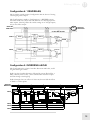
The Configuration Function [40 CONFIGURATION] .................71
Configuration 1: 1 REVERB................................................................72
2
Table of Contents
Configuration 2: 2 REVERBS..............................................................73
Configuration 3: LEZLIE+REVERB...............................................74
Configuration 4: 1 REVERB+EQ ......................................................75
Configuration 5: OVERDRIVE+LEZLIE .......................................75
Selecting a Send to Edit [00-30 SEND]..............................................76
The EQ Function [50 EQ] ...................................................................76
The Mod Function [60 MOD].............................................................77
The Lezlie Function [70 LEZLIE]......................................................78
The Pitch Function [80 PITCH]..........................................................79
The Delay Function [90 DELAY] .......................................................82
The Reverb Function [100 REVERB] ................................................83
The Overdrive Function [110 OVERDRIVE]..................................87
Setting the Effects Output Levels [120 MIX]....................................88
Appendix A: Frequently Asked Questions ...89
How do I split the keyboard? ...............................................................89
How do I layer two sounds on the keyboard? ...................................89
What is a MIDI Sequence? ...................................................................89
Where can I get MIDI sequences for the QS? ..................................89
How do I play General MIDI sequences?..........................................89
How do I load sequences into my QS?...............................................89
How do I load samples into the QS? ..................................................90
Where can I get Q Cards?.....................................................................90
Where can I get SRAM cards and Flash cards?.................................90
Where can I get more Banks?...............................................................90
Are QS6.2/QS8.2 Programs compatible with older QS
programs? ................................................................................................90
How do I change what the sliders do?................................................90
Appendix B: Sound Bridge...............................91
Appendix C: MIDI Supplement .......................93
Appendix D: Troubleshooting .........................97
Recovering from a Crash.......................................................................98
Re-Initializing ..........................................................................................98
Checking the Software Version ............................................................98
Cleaning Your QS...................................................................................98
Specifications ......................................................99
Index......................................................................101
Warranty/Contact Alesis...................................103
3
Introduction
Welcome!
Congratulations on your purchase of an Alesis QS6.2/QS8.2 64-Voice
Expandable Synthesizer! It’s a powerful instrument and we’re sure you
will find it exciting to use!
Those of you who are familiar with the enormously-popular QS-line of
synthesizers may be wondering, "What has changed in the new QS6.2
and QS8.2?".
Well, we've kept the same great sound engine but totally redesigned the
output section. We replaced the 18-bit D/A (digital-to-analog)
converters with vastly superior Alesis 24-bit audio converters, resulting in
a tremendous improvement in sound quality (much higher signal-to-noise
ratio, and much lower distortion). You can hear the difference in the
crystal-clear sounds. Go ahead - turn up the volume... We also refined
the look of the keyboards and rearranged the front panel controls to
make them more intuitive and improve ergonomics.
In addition, we improved the little, but important, things. The User Bank
Programs have been completely updated. The rear-panel jacks have been
moved to make the QS6.2 fit on certain kinds of stands better. We even
re-wrote the manual and added a FAQ with the questions we've received
the most over the years.
And don't forget, like their predecessors, the QS6.2 and QS8.2 are
expandable. With an Alesis Q-Card ROM expansion, you get 8MB of
additional professional-quality samples to add to your palette, in whatever
genre of music you're into. Ask your music dealer about Alesis Q-Cards.
Be sure to register your QS synthesizer on the Alesis website,
www.alesis.com. Here, you will find some cool items to go with your QS
synthesizer, like additional sound Banks and Sound Bridge software.
We hope your investment will bring you many years of creative
enjoyment and help you achieve your goals.
Sincerely,
The people of Alesis
5
Introduction
Unpacking and Inspection
The shipping carton for your QS should contain the following items:
•
•
•
•
QS synthesizer
Sustain pedal
AC power cable
This instruction manual
Please log on to the Alesis website at www.alesis.com to register your new
QS synthesizer. This will help us give you the best support we possibly
can.
How to Use This Manual
We’re sure you’d like to jump in and start using your QS synthesizer
quickly. To help you do this, refer to Chapter 1 for hook-up instructions,
then follow the “First Session” tutorial in Chapter 2. This will get you
playing in no time. If you have any questions, refer to the FAQ in
Chapter 12.
For more information on other features of your QS (such as how to use
it with expansion cards and MIDI), refer to Chapters 3 through 6.
True synthesists who want to create their own sounds should refer to
Chapters 7 through 11.
Near the end of the manual are troubleshooting tips, specifications, and
an Index to help you find what you're looking for.
New terms are shown in bold. All buttons, knobs, and switches on the
QS are referred to in bracketed capital letters that match the instrument’s
actual markings. Here are some examples:
[PROGRAM] refers to the button to the right of the display that says
“PROGRAM” on it.
[CONTROLLER D] is the slider with “D” printed underneath.
[00] refers to one of numbered buttons to the right of the display.
[PITCH] is the control wheel at the left side of the instrument.
[SUS PEDAL] is the rear panel jack you’d plug the sustain pedal into.
6
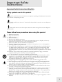
Helpful tips and advice are highlighted in a
shaded box like this
When something important appears in the
manual, an exclamation mark (like the one
shown at left) will appear with some
explanatory text.
Important Safety
Instructions
Important Safety Instructions (English)
Safety symbols used in this product
This symbol alerts the user that there are important operating and maintenance instructions
in the literature accompanying this unit.
This symbol warns the user of uninsulated voltage within the unit that can cause dangerous
electric shocks.
This symbol warns the user that output connectors contain voltages that can cause dangerous
electrical shock.
Please follow these precautions when using this product:
1.
2.
3.
4.
5.
6.
7.
8.
9.
10.
11.
12.
13.
14.
15.
16.
17.
18.
Read these instructions.
Keep these instructions.
Heed all warnings.
Follow all instructions.
Do not use this apparatus near water.
Clean only with a damp cloth. Do not spray any liquid cleaner onto the faceplate, as this may
damage the front panel controls or cause a dangerous condition.
Install in accordance with the manufacturer's instructions.
Do not install near any heat sources such as radiators, heat registers, stoves, or other apparatus
(including amplifiers) that produce heat.
Do not defeat the safety purpose of the polarized or grounding-type plug. A polarized plug has
two blades with one wider than the other. A grounding-type plug has two blades and a third
grounding prong. The wide blade or the third prong are provided for your safety. When the
provided plug does not fit into your outlet, consult an electrician for replacement of the obsolete
outlet.
Protect the power cord from being walked on or pinched, particularly at plugs, convenience
receptacles, and the point where they exit from the apparatus.
Use only attachments or accessories specified by the manufacturer.
Use only with a cart, stand, bracket, or table designed for use with professional audio or music
equipment. In any installation, make sure that injury or damage will not result from cables
pulling on the apparatus and its mounting. If a cart is used, use caution when moving the
cart/apparatus combination to avoid injury from tip-over.
Unplug this apparatus during lightning storms or when unused for long periods of time.
Refer all servicing to qualified service personnel. Servicing is required when the apparatus has
been damaged in any way, such as when the power-supply cord or plug is damaged, liquid has
been spilled or objects have fallen into the apparatus, the apparatus has been exposed to rain or
moisture, does not operate normally, or has been dropped.
This unit produces heat when operated normally. Operate in a well-ventilated area with at least
six inches of clearance from peripheral equipment.
This product, in combination with an amplifier and headphones or speakers, may be capable of
producing sound levels that could cause permanent hearing loss. Do not operate for a long
period of time at a high volume level or at a level that is uncomfortable. If you experience any
hearing loss or ringing in the ears, you should consult an audiologist.
Do not expose the apparatus to dripping or splashing. Do not place objects filled with liquids
(flower vases, soft drink cans, coffee cups) on the apparatus.
WARNING: To reduce the risk of fire or electric shock, do not expose this apparatus to rain or
moisture.
7
Important Safety Instructions
Instructions de Sécurité Importantes (French)
Symboles utilisés dans ce produit
Ce symbole alèrte l’utilisateur qu’il existe des instructions de fonctionnement et de
maintenance dans la documentation jointe avec ce produit.
Ce symbole avertit l’utilisateur de la présence d’une tension non isolée à l’intérieur de
l’appareil pouvant engendrer des chocs électriques.
Ce symbole prévient l'utilisateur de la présence de tensions sur les raccordements de sorties,
représentant un risque d'électrocution.
Veuillez suivre ces précautions lors de l’utilisation de l’appareil:
1.
2.
3.
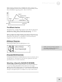
4.
5.
6.
Lisez ces instructions.
Gardez ces instructions.
Tenez compte de tous les avertissements.
Suivez toutes les instructions.
N’utilisez pas cet allareil à proximité de l’eau.
Ne nettoyez qu’avec un chiffon humide. Il est potentiellement dangereux d'utiliser des
pulvérisateurs ou nettoyants liquides sur cet appareil.
7. Installez selon les recommandations du constructeur.
8. Ne pas installer à proximilé de sources de chaleur comme radiateurs, cuisinière ou autre appareils
(don’t les amplificateurs) produisant de la chaleur.
9. Ne pas enlever la prise de terre du cordon secteur. Une prise murale avec terre deux broches et
une troisièrme reliée à la terre. Cette dernière est présente pour votre sécurité. Si le cordon
secteur ne rentre pas dans la prise de courant, demandez à un électricien qualifié de remplacer la
prise.
10. Evitez de marcher sur le cordon secteur ou de le pincer, en particulier au niveau de la prise, et aux
endroits où il sor de l’appareil.
11. N’utilisez que des accessoires spécifiés par le constructeur.
12. N’utilisez qu’avec un stand, ou table conçus pour l’utilisation d’audio professionnel ou
instruments de musique. Dans toute installation, veillez de ne rien endommager à cause de câbles
qui tirent sur des appareils et leur support.
13. Débranchez l’appareil lors d’un orage ou lorsqu’il n’est pas utilisé pendant longtemps.
14. Faites réparer par un personnel qualifié. Une réparation est nécessaire lorsque l’appareil a été
endommagé de quelque sorte que ce soit, par exemple losrque le cordon secteur ou la prise sont
endommagés, si du liquide a coulé ou des objets se sont introduits dans l’appareil, si celui-ci a été
exposé à la pluie ou à l’humidité, ne fonctionne pas normalement ou est tombé.
15. Puisque son fonctionement normale génère de la chaleur, placez cet appareil au moins 15cm. des
équipments péripheriques et assurez que l’emplacement permet la circulation de l’air.
16. Ce produit, utilisé avec un amplificateur et un casque ou des enceintes, est capable de produite des
niveaux sonores pouvant engendrer une perte permanente de l’ouïe. Ne l’utilisez pas pendant
longtemps à un niveau sonore élevé ou à un niveau non confortable. Si vous remarquez une perte
de l’ouïe ou un bourdonnement dans les oreilles, consultez un spécialiste.
17. N'exposez pas l'appareil à l'égoutture ou à l'éclaboussement. Ne placez pas les objets remplis de
liquides (vases à fleur, boîtes de boisson non alcoolique, tasses de café) sur l'appareil.
18. AVERTISSEMENT: Pour réduire le risque du feu ou de décharge électrique, n'exposez pas cet
appareil à la pluie ou à l'humidité.
8
Important Safety Instructions
Lesen Sie bitte die folgende Sicherheitshinweise (German)
Sicherheit Symbole verwendet in diesem Produkt
Dieses Symbol alarmiert den Benutzer, daß es wichtige Funktionieren und Wartung Anweisungen in
der Literatur gibt, die diese Maßeinheit begleitet.
Dieses Symbol warnt den Benutzer der nicht isolierten Spannung innerhalb der Maßeinheit, die
gefährliche elektrische Schläge verursachen kann.
Dieses Symbol warnt den Benutzer, dem Ausgabestecker Spannungen enthalten, die gefährlichen
elektrischen Schlag verursachen können.
Folgen Sie bitte diesen Vorkehrungen, wenn dieses Produkt verwendet
wird:
1.
2.
3.
4.
5.
6.
Lesen Sie die Hinweise.
Halten Sie sich an die Anleitung.
Beachten Sie alle Warnungen.
Beachten Sie alle Hinweise.
Bringen Sie das Gerät nie mit Wasser in Berührung.
Verwenden Sie zur Reinigung nur ein weiches Tuch. Verwenden Sie keine flüssigen Reinigungsmittel. Dies
kann gefährliche Folgen haben.
7. Halten Sie sich beim Aufbau des Gerätes an die Angaben des Herstellers.
8. Stellen Sie das Gerät nich in der Nähe von Heizkörpern, Heizungsklappen oder anderen Wärmequellen
(einschließlich Verstärkern) auf.
9. Verfehlen Sie nicht den Zweck des grounging Terminals auf dem Netzstecker. Dieses Terminal wird für
Ihre Sicherheit zur Verfügung gestellt.
10. Verlegen Sie das Netzkabel des Gerätes niemals so, daß man darüber stolpern kann oder daß es
gequetscht wird.
11. Benutzen Sie nur das vom Hersteller empfohlene Zubehör.
12. Verwenden Sie ausschließlich Wagen, Ständer, oder Tische, die speziell für professionelle Audio- und
Musikinstrumente geeignet sind. Achten Sie immer darauf, daß die jeweiligen Geräte sicher installiert sind,
um Schäden und Verletzungen zu vermeiden. Wenn Sie einen Rollwagen benutzen, achten Sie darauf, das
dieser nicht umkippt, um Verletzungen auszuschließen.
13. Ziehen Sie während eines Gewitters oder wenn Sie das Gerät über einen längeren Zeitraum nicht
benutzen den Netzstecher aus der Steckdose.
14. Die Wartung sollte nur durch qualifiziertes Fachpersonal erfolgen. Die Wartung wird notwendig, wenn
das Gerät beschädigt wurde oder aber das Stromkabel oder der Stecker, Gegenstände oder Flüssigkeit in
das Gerät gelangt sind, das Gerät dem Regen oder Feuchtigkeit ausgesetzt war und deshalb nicht mehr
normal arbeitet oder heruntergefallen ist.
15. Dieses Gerät produziert auch im normalen Betrieb Wärme. Achten Sie deshalb auf ausreichende Lüftung
mit mindestens 15 cm Abstand von anderen Geräten.
16. Dieses Produkt kann in Verbindung mit einem Verstärker und Kopfhörern oder Lautsprechern
Lautstärkepegel erzeugen, die anhaltende Gehörschäden verursachen. Betreiben Sie es nicht über längere
Zeit mit hoher Lautstärke oder einem Pegel, der Ihnen unangenehm is. Wenn Sie ein Nachlassen des
Gehörs oder ein Klingeln in den Ohren feststellen, sollten Sie einen Ohrenarzt aufsuchen.
17. Setzen Sie den Apparat nicht Bratenfett oder dem Spritzen aus. Plazieren Sie die Nachrichten, die mit
Flüssigkeiten (gefüllt werden Blumevases, Getränkdosen, Kaffeetassen) nicht auf den Apparat.
18. WARNING: um die Gefahr des Feuers oder des elektrischen Schlages zu verringern, setzen Sie diesen
Apparat nicht Regen oder Feuchtigkeit aus.
9
Important Safety Instructions
CE Declaration Of Conformity
See our website at:
http://www.alesis.com
FCC Compliance Statement
This device complies with Part 15 of the FCC rules. Operation is subject
to the following two conditions: (1) This device may not cause harmful
interference and (2) this device must accept any interference received,
including interference that may cause undesired operation.
NOTE: This equipment has been tested and found to comply with the
limits for a Class B digital device, pursuant to Part 15 of the FCC Rules.
These limits are designed to provide reasonable protection against
harmful interference in a residential installation. This equipment
generates, uses and can radiate radio frequency energy and, if not
installed and used in accordance with the instructions, may cause harmful
interference to radio communications. However, there is no guarantee
that interference will not occur in a particular installation. If this
equipment does cause harmful interference to radio or television
reception, which can be determined by turning the equipment off and
on, the user is encouraged to try to correct the interference by one or
more of the following measures:
-- Reorient or relocate the receiving antenna.
-- Increase the separation between the equipment and receiver.
-- Connect the equipment into an outlet on a circuit different from that
to which the receiver is connected.
-- Consult the dealer or an experienced radio/TV technician for help.
10
1 Connections
Connecting AC Power
Before making any power connections, make sure the QS’s power switch
is turned off.
1. Plug the female end of the power cable into the QS’s power socket.
2. Plug the male (plug) end into a properly grounded power outlet.
WARNING: Make sure the outlet is
properly grounded. Plugging the QS into an
ungrounded outlet can be hazardous.
Making Audio Connections
There are several ways to hook up your QS synthesizer audio outputs:
• Mono. Connect a cable from either of the QS’s [MAIN] outputs to an
amp or mixer input. The QS will automatically route both left and right
channels to that output.
• Stereo. Connect two cables from the QS’s [LEFT] and [RIGHT]
outputs to two inputs of an amp or mixer.
• Headphones. Plug a set of headphones into the [HEADPHONES]
jack on the rear panel.
WARNING: When connecting audio cables
or turning power on and off, make sure that
the amplifiers in your system are turned off
or the volume controls are turned down. If
you don’t do this, you can create loud bursts
of sound that might damage your speakers.
Connecting the Foot Pedals
The QS has two pedal jacks marked [SUS PEDAL] and [PEDAL 1].
Plug the included sustain pedal into the jack marked [SUS PEDAL].
[SUS PEDAL] is designed to work with any standard momentary
footswitch. It doesn’t matter whether the footswitch is normally open or
closed, as long as you plug it in before powering up your QS; the
instrument will calibrate itself.
[PEDAL 1] is designed to work with a Roland EV-5 pedal or equivalent.
NOTE: If your sustain pedal responds
backwards (i.e., notes sustain when your foot
is off the pedal), turn off your QS and make
sure the footswitch plug is fully inserted into
the [SUS PEDAL] jack. Then, turn the QS
back on while keeping your foot off the
footswitch.
11
1
Connections
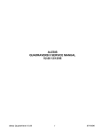
Connection Diagram
12
2 First Session
Playing the Demos
The QS has five built-in demo sequences. To play a demo, hold down
[MIX] and press a number button from [0] through [4]. Playback will
start with the specified demo and continue through the remaining demos.
To stop the demo, press [MIX].
Demos:
0. “Jinx” by James Reynolds
1. “Bang!” by Taiho Yamada
2. ”Dreamcurrents” by Erik Norlander
3. “Iron Man” by Keith Emerson
4. “Camera Obscura” by David Bryce
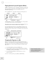
Playing Programs
The sounds in your QS are called Programs. Programs contain all of
the parameters that are needed to define a sound. For example, “True
Stereo” is a grand piano Program.
To select a Program, press the [PROGRAM] button. The display should
look something like this:
Press the [BANK] buttons to choose a Program Bank. Available choices
are USER, PRESET1, PRESET2, PRESET3, and GenMIDI. More
Banks are available if you have an expansion card.
To call up an individual Program, press the numbered buttons for the
Program you want to recall.
For example, if you want to hear a grand piano Program, press the
[BANK >] button until you are in the PRESET1 Bank, then press the [00
PIANO] button and then the [0] button. This will select Program 00,
“True Stereo”.
You can also use the [VALUE UP] and [VALUE DOWN] buttons step
through the Programs.
Finding Programs
To make Programs easier to find, we’ve organized them into eleven
categories marked on the “tens” buttons:
00-09 Pianos
10-19: Chromatic
30-39 Guitar
40-49 Bass
60-69: Brass
70-79 Winds
110-119: Rhythm/FX
20-29: Organ
50-59: Strings
80-109 Synth
120-127: Drums/Percussion
For example, Programs 20 through 29 are all Organ sounds.
NOTE: The General MIDI (GenMIDI) Bank
doesn’t follow this convention; it is
organized to match the General MIDI
standard, which puts Programs in a different
order.
13
2
First Session
Playing Split and Layered Programs (Mixes)
A Mix is a combination of up to 16 Programs, allowing you to play more
than one sound at the same time. The Programs may be split or layered
across the keyboard, or distributed among MIDI channels for
multitimbral sequencing.
Press the [MIX] button. The display should look something like this:
Use the [BANK], [VALUE] or the numbered buttons to call up the Mix
of your choice (the same way you select Programs).
The numbers at the bottom of the display show which Mix Channels are
enabled in this Mix. Each Mix Channel contains a Program.
To see what Programs the Mix uses, use the [PAGE >] button to step
through the Mix Channels. The selected Mix Channel will blink at the
bottom of the screen and the name of the Program on that channel will
be displayed.
Changing the Programs in a Mix
Suppose you’re playing a Mix that has two Programs split across the
keyboard: a bass sound on the lower half, and a piano on the upper half.
Now suppose you want to choose a different bass Program for the lower
half. To do this, you need to change the Program in that Mix Channel.
Here’s how:
1)
Get into Mix Mode by pressing the [MIX] button.
2)
Press the [PAGE >] button to select the Mix Channel containing
the Program you want to change. The selected Mix Channel should
be flashing at the bottom of the display.
3)
Use the [VALUE], [BANK] or numbered buttons to select a
different Program.
To return to normal operation, press [MIX] or [PROGRAM].
14
NOTE: Your QS will let you change
Programs on all 16 Mix Channels, even ones
that aren’t yet enabled in this Mix. You
won’t hear the changes you make to a
channel that isn’t yet enabled.
First Session
2
Selecting Banks
A Bank is a collection of 128 Programs and 100 Mixes. There are five
internal Banks available in the QS, and more can be accessed if you put a
card into the [PCMCIA EXPANSION CARD] slot.
The internal Banks are:
USER
PRESET1
PRESET2
PRESET3
GenMIDI
To explore different Banks, use the [< BANK] and [BANK >] buttons.
NOTE: You can overwrite the Programs
and Mixes in the User Bank. The other
Banks are permanent.
Using the Performance Controls
The QS provides various ways to control the sound as you are playing:
• Keyboard Velocity lets you control the sound by how hard you hit the
keys. Depending on how hard you play, the volume and tonal quality
of the sound will change.
• Keyboard Aftertouch (QS6.2 only) lets you change the sound by
pressing down hard on the keys after you’ve played them. While
holding key down, you can press harder on it to change the character
of the sound.
• The Sustain Pedal is used to hold notes after you let go of the keys.
• Pedal 1 is most often used to control the volume, but it can be used to
control other parameters.
• The Pitch Bend Wheel allows you to alter the pitch of the notes as
you play.
• The Modulation Wheel allows you to add a modulation effect (such
as vibrato or tremolo) to the sound.
• The Controller A-D Sliders allow you to affect various parameters of
the sound. In most of the presets, slider [A] controls a filter or filtersweep effect, [B] a delay effect, [C] an envelope time, and [D] a reverb
effect. As you move the sliders, the LCD gives you visual feedback in
the form of small vertical bar graphs.
NOTE: If you don’t see a bar graph in the
display when you move a slider, it means the
slider has no function in that particular
Program.
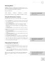
Transposing the Keyboard
1)
Hold down the [TRANSPOSE] button.
2)
Tap the key that represents the interval you’d like to shift by relative
to Middle C. For example, if you want to shift up a semitone, tap
the C-sharp key.
3)
Let go of the [TRANSPOSE] button. An up or down arrow will
appear in the [TRN] area of the LCD depending on which direction
you’ve transposed.
When you want to return things to normal, hold down [TRANSPOSE]
again and tap on Middle C (marked by a small triangle on the front
panel).
TIP: Using this method, you can transpose
up or down by as much as one octave. To
transpose by a greater interval, use the
Global transpose page.
15
2
First Session
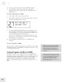
Storing and Copying
It is easy to store and copy Programs and Mixes. To do this:
16
1)
Press [STORE]. The display will look something like this:
TIP: The factory User Bank Mixes and
Programs are available on the Alesis
website.
2)
Pick a USER Bank destination using the numbered buttons, the
[VALUE] buttons or the [CONTROLLER D] slider.
NOTE: The PRESET and GenMIDI banks
reside in ROM, so they can’t be overwritten
with new Programs and Mixes.
3)
If you want the Program or Mix to be stored on an SRAM card in
the [PCMCIA EXPANSION SLOT], use the [BANK] buttons to
select a card bank.
4)
Press [STORE] again.
3 Overview
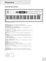
The Front Panel Controls
From left to right, we have:
[PITCH] Bend Wheel – for bending pitch during performance.
[MODULATION] Wheel – for adding vibrato and tremolo during performance.
[VOLUME] Slider– sets the output level.
[CONTROLLER A-D]/[EDIT VALUE] Sliders – for adjusting parameters
during performance or Edit mode.
[PAGE] Buttons – sets the MIDI or Mix channel; in the Edit Modes, these are used
to navigate through display pages.
[VALUE] Buttons – increase or decrease the currently selected value any Edit
Mode.
[EDIT] Button – for entering one of the Edit Modes (Mix, Program, Effects).
[STORE] Button – for storing or copying to the User Bank, an expansion card, or
external MIDI devices.
[<BANK]/[COMPARE] Button – selects a Bank; in an Edit Mode, compares the
current version to the original version.
[BANK>]/[GLOBAL] Button – selects a Bank; in an Edit Mode, access the Global
parameters.
[MIX] Button – for entering Mix Mode.
[PROGRAM] Button – for entering Program Mode.
[00]-[120] Numbered Buttons – selects Program and Mix categories; in an Edit
Mode, these select Edit functions.
[0]-[9] Buttons – selects individual Programs or Mixes; in Edit Mode, these select
edit functions.
[SEQ SELECT] Button – triggers a sequence stored on the Expansion Card.
[TRANSPOSE] Button – transposes the keyboard. Hold this button and touch a
key.
17
3
Overview
The Play Modes
We’ve already introduced you to these modes in the last chapter. This is
where you’ll normally be when you’re playing your QS.
Program Mode
In this mode, you can play the QS’s various Programs one at a time.
You’ll probably be in this mode most of the time. The QS contains 512
Preset and 128 User Programs. To get into Program Mode, press the
[PROGRAM] button.
Mix Mode
In this mode, you can play up to 16 Programs at the same time. You can
use this mode to create keyboard splits or keyboard layers, or for
multitimbral sequencing. The QS contains 400 Preset Mixes and 100
User Mixes. To get into Mix Mode, press the [MIX] button.
What the Other Buttons Do
When in Mix or Program Mode, the buttons have the following
functions:
•
•
•
•
18
The numbered buttons select different Programs and Mixes.
The [VALUE] buttons step through the Programs and Mixes.
The [PAGE] buttons change the MIDI channel.
The [BANK] buttons step through the Banks.
Overview
3
The Edit Modes
The Edit Modes are used to change the QS’s sounds and various
parameters. Many people are perfectly happy using their QS without
ever editing a sound. However, if you like to tweak and create your own
sounds, you’ll be using these modes.
Program Edit Mode
In this mode, you can change the settings that make up a Program or
create an entirely new Program from scratch. To get into Program Edit
Mode, press the [EDIT] button from Program Mode.
Mix Edit Mode
In this mode, you can change the settings that make up a Mix or create
an entirely new Mix from scratch. To get into Mix Edit Mode, press the
[EDIT] button from Mix Mode.
Effects Edit Mode
In this mode, you can change the settings of the QS’s internal digital
effects processor. To get into Effects Edit Mode, press the [EDIT]
button twice from Program mode or three times from Mix Mode.
Navigating and Entering Data
When in one of the Edit modes, the buttons have the following
functions:
• The numbered buttons select an Edit function.
• The [< PAGE] and [PAGE >] buttons cycle through the pages of the
function. You can always tell what page you are on by looking at the
indicator in the upper right corner of the display. (For example, “P1”
for Page One).
• The [VALUE UP] and [VALUE DOWN] buttons increment or
decrement parameter values.
• [CONTROLLER D] can also be used for setting parameter values.
• The [< BANK] button (Compare) lets you compare the edited sound
to the original sound.
• The [BANK >] button gets you into Global Mode (see below)
19
3
Overview
Global and Store Modes
Global Mode
In this mode, you can set various aspects of the QS that don’t change
whenever a new Program or Mix is selected (for example, the keyboard
sensitivity). Press the [EDIT] button, then the [BANK >] button (with
[GLOBAL] written under it) to get into this mode.
Store Mode
This mode is for storing, copying and transmitting data. You can store
or copy whole Banks, individual Mixes, individual Programs, and Effects
settings, among other things. Press the [STORE] button to get into this
mode.
Navigating and Entering Data
This works the same as in the Edit modes, except that the [BANK]
buttons don’t do anything.
Special Editing Features
Compare
In any Edit mode, the [< BANK] button performs the [COMPARE]
function (see the label under the button).
If you press [COMPARE] from any Edit mode, the original Program or
Mix will be temporarily recalled and “EDIT” will flash in the display.
Pressing [COMPARE] again switches to your edited version.
Resetting Parameter Values
While editing, you can quickly reset parameters back to their default
values by pressing both of the [VALUE] buttons at the same time.
Pressing both of the [PAGE] buttons at the same time will jump to the
first page.
In Program or Mix Modes, pressing the [PAGE] buttons at the same
time will set the QS to MIDI channel 1. Pressing the [BANK] buttons at
the same time will jump to the User Bank.
20
NOTE: This is also known as the “Double
Button Press Trick”
4 Expansion Cards
PCMCIA Expansion Cards
If you want more Sounds (samples), Programs, Mixes, or Sequences, all
you have to do is insert the appropriate card into the QS’s [PCMCIA
EXPANSION SLOT].
There are three kinds of expansion cards that you can use:
• QCards are a series of excellent ROM (read-only memory) cards
developed by Alesis. Each contains 8MB of professional
uncompressed PCM samples plus Programs and Mixes designed to
take full advantage of them. The cards available are Classical,
Sanctuary, Vintage Keyboards, Vintage Synthesizers, HipHop,
EuroDance, Latin, Stereo Classical Piano, and Stereo Jazz Piano. You
can get these at your Alesis dealer.
TIP: If you own a Q-Card, you can get
additional sound banks to go with that QCard on the Alesis website.
• SRAM cards provide additional storage for Programs and Mixes. A
512K SRAM card can hold eight Banks of Programs and Mixes. You
can edit these as you wish. Many different SRAM cards from 256K to
8 Megabytes are supported; just make sure they are 5-volt read/write
only, and have an access time of 120 nanoseconds or faster.
• Flash cards provide additional sample memory that you can fill with
your own sounds using a computer! The QS can accommodate 2MB,
4MB, and 8MB flash cards (larger cards will work, but only the first
8MB will be utilized by the QS). Using Alesis’ Sound Bridge software
on your PC or Mac, you can download samples into the Flash card
through MIDI. Flash cards must be Type 1 PC cards (PCMCIA), and
must be AMD-C series or -D series FLASH or compatible, with an
access time of 120ns or faster.
Playing Card Sounds
To play the sounds on an expansion card, enter Mix or Program mode
and use the [BANK] buttons to select the Card Bank. Up to 8 Card
Banks can be recognized.
Playing Card Sequences
Several of the Alesis QCards come with their own demonstration
sequences. In addition, you can store your own MIDI sequences to RAM
or FLASH cards using a computer and Alesis’ free Sound Bridge
software.
21
4
Expansion Cards
To play back a card sequence:
1)
Insert the card containing sequence data into the [PCMCIA
EXPANSION SLOT].
2)
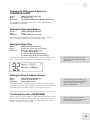
Press the [SEQ SELECT] button. The display will look like this:
3) Use the [00] through [40] buttons to pick the tens digit of the
sequence number.
4)
Finally, use the [0] through [9] buttons to play a specific sequence.
To stop a sequence while it’s playing, you can press the [SEQUENCE],
[PROGRAM] or [MIX] button.
Saving a Bank to an SRAM Card (Formatting)
Before you can use a blank SRAM card for the first time, you must
format it by storing the User Bank to each of its banks. Depending on
the amount of SRAM a particular card has, up to 8 complete Banks can
be stored onto it.
1 ) Insert an SRAM card into the [PCMCIA EXPANSION SLOT].
2 ) Press [STORE].
3 ) Press [< PAGE] three times. This selects the “SAVE TO CARD”
option.
4 ) Use the [CONTROLLER D] slider or the [VALUE] buttons to
select a bank location on the card to store to.
5 ) Press [STORE] to transfer the User Bank data from the QS onto
the card.
Saving a Program or Mix to an SRAM Card
This is done just like storing to the User Bank, except that you use the
[BANK] buttons to select a card bank.
Note that the SRAM card must be formatted first (see above).
Loading Banks from a Card
The QS can access Program and Mix data directly from a card by using
the [BANK] buttons. However, there may be an instance where you
want to load a full bank from a card into the User Bank. Warning: this
will erase the current Programs and Mixes in your User Bank.
To overwrite the User Bank with a Card bank:
1 ) Insert the card into the card slot on the back panel.
2 ) Press [STORE].
3 ) Press [< PAGE] twice. This selects the “LOAD FROM CARD”
option.
22
NOTE: If the display reads “CARD IS
WRITE PROTECTED.” switch the writeprotect switch on the card to off and repeat
the procedure.
Expansion Cards
4
4 ) Use the [CONTROLLER D] slider or the [VALUE] buttons to
select the bank on the card you wish to load (A1–A4, etc.).
5 ) Press [STORE] to transfer the data from the card into the QS.
Loading a Program or Mix from a Card
To load a single Mix or Program from a card into the User Bank, first
select the Mix or Program, then use the Store Function to store it in the
User Bank.
Note that when storing a Mix from a Card into the User Bank, the
individual Programs used by the Mix will not be moved into the User
Bank.
If the Mix or Program you wish to transfer uses samples that reside on a
ROM card, you must have the ROM card in the slot after the transfer in
order for that portion of the Program or Mix to sound the same (or at
all).
Transferring Mix Banks
Whenever you transfer an internal Bank to an SRAM card, all Mixes in
the transferred Bank are automatically modified so that they access the
Programs on the card Bank instead of the internal Bank. And, when a
card Bank is transferred to the User Bank, the opposite happens – all
Programs within a Mix which had previously accessed the card Bank
point to the User Bank.
When an individual Mix is transferred, it is not modified in any way. The
modification only occurs when an entire bank is transferred.
Generally, it’s a good idea to make banks self-contained. That is, all
Mixes in a bank should access only Programs that are in the same bank.
You don’t have to do this, but it makes things easier when copying banks.
23
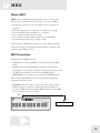
5 MIDI
What is MIDI?
MIDI stands for Music Instrument Digital Interface. It allows music
instruments to communicate with each other. You can use MIDI to:
• Record what you play on your QS synthesizer into a sequencer or
computer.
• Play back sequences from a sequencer or computer on your QS.
• Store and recall Programs and Mixes on a computer.
• Use a computer to edit your QS’s sounds.
• Use your QS to control another synthesizer or sound module.
• Use another keyboard to play your QS’s sounds.
Some examples of MIDI devices besides your QS synthesizer include
keyboard controllers, sound modules, drum machines, sequencers, and
computers with MIDI interfaces.
MIDI Connections
The QS has three MIDI connectors:
• [MIDI IN] is for receiving MIDI information from another MIDI
device.
• [MIDI OUT] is for sending MIDI information to another device.
Depending on your settings, the data from this port can originate from
the QS itself or simply be echoed from the [MIDI IN] port.
• [MIDI THRU] echoes whatever is received on the [MIDI IN] port.
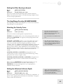
Here are four typical MIDI setups for your QS, and the appropriate
connections for each of them:
• Controller. With this setup, you can use your QS to “play” another
MIDI instrument (synthesizer, sound module, drum machine etc.).
Connect a MIDI cable from the QS’s [MIDI OUT] jack to the MIDI
IN of the device you want to control.
OUT
IN
Sound Module
25
5
MIDI
• Slave. With this setup, you can use another keyboard to play the
sounds on your QS. Connect a MIDI cable from the controller’s
MIDI OUT jack to the QS’s [MIDI IN] jack.
OUT
IN
Slave
Master
• Slave with pass-through. This setup allows MIDI signals to pass
through the QS so they may reach multiple units. This allows one
MIDI device to control several. Attach a cable from the MIDI OUT
of the first device to the [MIDI IN] jack of the QS; and then attach
another cable from the QS’s [MIDI THRU] jack to the MIDI IN of
the third device.
OUT
IN THRU
IN
Sound Module
• Sequencing. This setup allows you to use your QS with a MIDI
sequencer or a computer with a MIDI interface. Attach one MIDI
cable from the MIDI OUT of the sequencer or computer to the
[MIDI IN] jack of the QS. Attach another cable from the QS’s [MIDI
OUT] jack to the MIDI IN of the sequencer or computer.
IN
OUT
Computer
OUT
IN
26
MIDI
5
Using Your QS With a MIDI Sequencer
A sequencer is a device that records and plays back note messages. A
sequencer can take the form of a stand-alone hardware device, or a
computer with a MIDI interface and sequencing software.
Using a MIDI sequencer, you can record what you play on your QS, and
then play it back later. You can also obtain sequences written by other
people and play them back on your QS synthesizer. There are a large
number of General MIDI sequences available for just this purpose.
Since the QS is a multitimbral instrument, it is a perfect companion to a
sequencer. In Mix Mode, the QS can play up to 16 different programs
simultaneously. This means that if you play a multi-channel sequence
into your QS, it can sound like a whole band, ensemble, or even an
orchestra!
Changing the MIDI Channel
In order for MIDI to work, the MIDI Channel must be set properly. For
example, if you want one device to control another via MIDI, they must
be set to the same MIDI channel. There are 16 MIDI channels.
In Program Mode, the MIDI channel is indicated by a small number at
the bottom of the display. To change the MIDI channel, press either of
the [PAGE] buttons.
When there is MIDI activity (either from the MIDI port or the QS’s
keyboard) a small circle around the number will flash.
In Mix Mode, the MIDI channel will depend on how the Keyboard
Mode is set. The Keyboard Mode parameter is found on Page 6 of the
Global Pages. Please look at the “Global Parameters” section of this
manual to see how to set it.
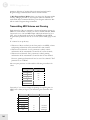
Saving Programs and Mixes Via MIDI
The QS lets you transmit your entire User Bank (Programs and Mixes) to
an external device (such as a computer, sequencer, storage device, or
another QS synthesizer) via MIDI.
NOTE: the QS sends and receives Bank,
Program and Mix data in MIDI sysex
format.
To send the entire User Bank (Programs and Mixes) via MIDI:
1 ) Connect a MIDI cable from the QS’s [MIDI OUT] jack to the
MIDI In of a device capable of receiving the data (a computer,
sequencer, another QS, etc.).
2 ) Press [STORE].
3 ) Press [PAGE >] six times to select the proper page of the Store
function. The display will look like this:
27
5
MIDI
4 ) Set up your receiving device to accept a MIDI sysex dump.
5.) Press [STORE] to transmit the data from the QS. While
transmitting the data, the display will read “SENDING OUT
MIDI DATA.....”.
To send a single Program via MIDI:
1 ) Follow steps 1 and 2 in the instructions above.
2 ) Press [PAGE >]seven times to select the proper page of the Store
function. The display will look like this:
3 ) Use the [CONTROLLER D] slider and the [VALUE] buttons to
select a Program to transmit. You may select any Program in the
User Bank (000 to 127) or the Program Edit buffer (EDIT) or any
of the 16 Mix Edit buffers (Em01 to Em16).
As this value is changed, the second parameter (destination) will
change also. If you hit [PAGE >] one more time, you can change
the destination number separately.
4 ) Press [STORE] to transmit the data out the [MIDI OUT]
connector.
To send a single Mix via MIDI:
The procedure for sending a single Mix is very similar to that of sending
a Program (see above). Hit [STORE], then [PAGE >] nine times to get
to the MIDI Mix Store page.
Loading Programs and Mixes Via MIDI
The QS doesn’t need to be in a special mode to receive MIDI sysex
information. Simply connect a MIDI cable from the MIDI out jack of
your MIDI player to the [MIDI IN] port of your QS and start the sysex
dump on your MIDI storage device or computer. If everything is
working properly, the QS display will read “RECEIVING MIDI
DATA...” and the Bank, Program, or Mix will be loaded into the User
Bank.
28
NOTE: Just because you’re storing a Mix to
MIDI doesn’t mean that all of the Programs
used by that Mix are being taken with it. If
you want that Mix to sound the same in
someone else’s QS, you’re going to need to
send along the Programs out of which it was
constructed.
NOTE: Some computers are not fast enough
to transmit MIDI sysex data properly. If you
are experiencing problems, try adjusting the
settings in your MIDI software. Some
programs allow you to slow down the
transmit rate so the computer hardware can
keep up with the software.
6 Global Parameters
What are the Global Parameters?
Certain basic parameters affect your entire QS. Because they affect
everything, they are called the Global Parameters.
Entering Global Mode
1)
Press [EDIT].
2)
Press the [BANK >] button (with [GLOBAL] written beneath it).
The display will look like this:
NOTE: The “P1” in the upper right corner
of the display stands for Page One, and it
tells you where you are among the Global
pages.
NOTE: Any changes you make in Global
Mode will be saved immediately without
having to press any additional buttons.
To exit Global Mode, press [MIX] or [PROGRAM].
The Global Pages
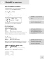
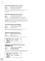
Setting the Master Pitch
Button:
[EDIT] [GLOBAL]
Page:
1
Parameter:
Master Pch (-12 to +12 semitones)
This parameter globally shifts the pitch of all sounds coming out of the
QS, whether triggered from the keyboard or from incoming MIDI
information. This parameter has no effect on MIDI Out note data.
NOTE: Changing MASTER PITCH can
alter QS drumkits in unpredictable ways,
because it shifts the key assignments of
multi-sampled drumkits in Keyboard Mode
but doesn’t shift Drum Mode sounds. Most
Preset drumkits are constructed using a
combination of the two.
Fine Tuning
Button:
[EDIT] [GLOBAL]
Page:
2
Parameter:
Master Tun (-99 to 99 cents)
This setting is like Master Pitch, but on a much finer scale. Its main use
will be to tune your QS to match other instruments. –99 to 99 cents is
equivalent to down or up one half-step (in hundredths of a semitone).
NOTE: This parameter does not have any
effect on Drum Mode sounds. However, it
will work to tune drums that are part of
multisampled Keyboard Mode drumkits.
They tune down or up as far as they can go
and then switch to the next keygroup, which
will probably be a different sample.
Picking the Keyboard Velocity Curve
Button:
[EDIT] [GLOBAL]
Page:
3
Parameter:
KbdCurv (WEIGHT, PLASTC, MAXMUM)
This parameter alters the QS keyboard’s velocity response.
29
6
Global Parameters
WEIGHT gives the keyboard the widest possible dynamic velocity range
for weighted keyboards (like the QS8.2’s).
PLASTC has a narrower dynamic velocity range associated with synth
keyboards (like the QS6.2’s). Notes played gently will be louder than they
would be if you had selected WEIGHT.
MAXMUM means that every note played on the keyboard is given the
maximum MIDI velocity, which is 127. In this mode, your QS’s keyboard
is no longer velocity-sensitive.
Setting the Keyboard Velocity Scaling
Button:
[EDIT] [GLOBAL]
Page:
4
Parameter:
Kbd Scaling (00 to 99)
This parameter adjusts the velocity sensitivity of the keyboard. At 00 the
keyboard is least sensitive. At 99, the keyboard will be very sensitive to
velocity. The default setting is 65.
Transposing the Keyboard
Button:
[EDIT] [GLOBAL]
Page:
5
Parameter:
Transpose (-31 to 31 in QS6.2, -19 to 19 in QS8.2)
This is the same type of Transpose that happens when you press the
[TRANSPOSE] button. It changes the MIDI Note Numbers assigned to
the keyboard, thus changing the note data sent out from your QS when
you play. On this page however, you enter the transpose amount by
using the standard [EDIT VALUE] slider and [VALUE] buttons, not by
pressing keys on the keyboard.
Setting the Keyboard MIDI Mode
Button:
[EDIT] [GLOBAL]
Page:
6
Parameter:
Kbd Mode (Norm, Solo, Out01-Out16)
This setting determines how the QS’s keyboard will work with respect to
MIDI and the internal QS engine.
Norm is the default setting. In Program Mode, the QS will receive and
transmit over the selected MIDI channel. In Mix Mode, MIDI is received
over all active MIDI channels, and sent over all active channels that have
MIDI OUT enabled.
Ch Solo is the same as NORMAL in Program Mode. In Mix Mode, it
only allows you to play the selected Mix channel from the keyboard and
only transmits on that MIDI channel. This is used to individually check
out the Programs that are in a Mix, or for multitimbral sequencing.
In this mode, you’ll only hear one Program at a time. If the keyboard is
split or layered in Mix Mode, you’ll only hear the Program on the current
Mix channel.
Out01 through Out16 select a single MIDI channel to transmit on, while
simultaneously shutting off local keyboard control. Use this mode if
you’ll be using your QS with an external sequencer controlling several
30
NOTE: This mode is automatically selected
by the QS when the General MIDI function
is set to ON.
NOTE: With this mode selected you will not
hear the QS unless your sequencer echoes
the MIDI data back to the QS’s MIDI IN
port. This is equivalent to the LOCAL OFF
setting in some synthesizers.
Global Parameters
6
MIDI devices. You’ll need to set your sequencer to echo back the MIDI
data that is being recorded.
Turning on General MIDI
Button:
[EDIT] [GLOBAL]
Page:
7
Parameter:
Genrl MIDI (ON, OFF)
This setting allows your QS to play any of the thousands of General
MIDI (“GM” for short) sequences that are available from the Internet
and other sources. Turning this ON will immediately put the QS into
Mix Mode and call up the GM Multi Mix.
Setting the A-D Controller MIDI Numbers
Button:
[EDIT] [GLOBAL]
Pages:
8 through 11
Parameter:
ControlrA-D (0 to 120)
These parameters let you select the MIDI Controller Numbers that will
be assigned to the A-D [CONTROLLER] sliders. This is useful both for
controlling external MIDI devices and for giving you sequencerrecordable control over Program and Effect parameters. The default
values are 012, 013, 091 and 093 for Controllers A-D respectively.
NOTE: The General MIDI spec reserves
MIDI Channel 10 for drumkits. Because of
this, when the General MIDI setting is ON,
your QS won’t be able to call up anything
but drumkits on Channel 10.
NOTE: Turning General MIDI ON
automatically sets your Keyboard Mode to
CH SOLO. Turning General MIDI off will
put the Keyboard Mode back the way it was.
NOTE: Some General MIDI sequences will
have a SysEx message at the beginning
which tells the receiving device to go into
General MIDI mode. The QS will respond to
such a message. If one comes in, then your
instrument will immediately jump from
wherever it is to the GM Multi Mix.
Setting the Pedal 1 MIDI Controller Number
Button:
[EDIT] [GLOBAL]
Page:
12
Parameter:
Ped1 Ctrl# (0 to 120)
Just like MIDI Controllers A–D, your QS’s [PEDAL 1] jack can be
assigned to a MIDI controller. The default is Controller 007 (Main
Volume). When set to this value, a pedal plugged into the back panel’s
Pedal 1 jack will automatically control volume.
Setting the Pedal 2 MIDI Controller Number
Button:
[EDIT] [GLOBAL]
Page:
13
Parameter:
Ped2 Ctrl# (0 to 120)
This setting works exactly like Pedal 1, just above. Even though the QS
does not have a Pedal 2 input, you can use this function to modulate QS
parameters through MIDI. The default for this setting is 004 (Foot
Controller).
Selecting the MIDI Program Change Behavior
Button:
[EDIT] [GLOBAL]
Page:
14
Parameter:
MIDI Prgsl (OFF, ON, CH1-16)
This parameter determines how your QS deals with MIDI Program
Change Commands.
When OFF, your QS will not send or respond to Program Change
messages.
31
6
Global Parameters
ON makes the QS send and respond to MIDI Program Changes. In
Program Mode it will send and receive Program Changes over the
currently selected MIDI channel. In Mix Mode, Program Changes are
received over all active MIDI channels, but sent only from those
displayed channels that have had MIDI OUT enabled. With this setting,
incoming Program Changes will only affect the Programs, not the entire
Mix.
NOTE: When you turn General MIDI
Mode ON, the MIDI Program Change
setting will be turned ON as well.
CH1 through CH16 are identical to ON as far as Program Mode is
concerned. In Mix mode, these settings allow you to change Mixes in
response to Program Change commands on the specified MIDI channel.
Program Changes coming in over other MIDI channels would continue
to work as before, changing any Programs associated with those channels
within the Mix.
Setting the Behavior of the MIDI Out Port
Button:
[EDIT] [GLOBAL]
Page:
15
Parameter:
MIDI Out (OUT, THRU)
This determines the behavior of the [MIDI OUT] port.
When set to OUT, MIDI data from the QS will be sent to the [MIDI
OUT] port. This is the default setting.
When set to THRU, a copy of what is received from the [MIDI IN]
port will be echoed to the [MIDI OUT] port (with no MIDI data from
the QS mixed in). In other words, the [MIDI OUT] port will act as a
MIDI THRU.
Resetting the A-D Controllers
Button:
[EDIT] [GLOBAL]
Page:
16
Parameter:
RESET A-D (ON, OFF)
This parameter determines whether the values for Controllers A–D will
reset to zero or stay the same whenever a new Program or Mix is chosen.
The default is ON, which resets the A-D Controllers to zero whenever
you change Programs or Mixes.
Setting the A-D Controller MIDI Mode
Button:
[EDIT] [GLOBAL]
Page:
17
Parameter:
A-D MODE (LOCAL, MIDI, BOTH)
This parameter determines how the A-D [CONTROLLER] sliders will
work.
LOCAL makes the sliders control the QS without sending MIDI data.
MIDI makes the sliders send out MIDI data, but have no effect on the
QS.
BOTH makes the sliders control your QS and send MIDI data. This is
the default setting.
32
TIP: If you are using [CONTROLLER]
sliders to affect the volumes of external
MIDI sound modules, you probably want to
set this parameter to OFF. That way you
won’t reset all the different modules to zero
volume every time you changed Programs.
Otherwise, you will probably want to leave
this ON.
7 Editing Programs
QS Composite Synthesis™
The QS generates sound through the use of QS Composite Synthesis™.
The basis of this technology is the playback and processing of audio
samples. A sample is a digital recording of a sound. The sound could
be a sine wave, a grand piano, or even a full orchestra.
The QS processes these samples by applying filters, envelopes and
modulations, and then mixing them with other processed samples. In
this way, the QS can create a universe of sounds.
The Voice
The part of the QS that plays back a sample is called a Voice. The QS
has 64 Voices, so it can play 64 sounds at the same time.
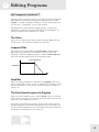
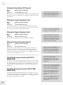
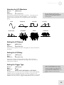
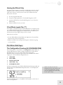
Lowpass Filter
The output of the Voice feeds into a lowpass filter, which dampens
high frequencies and allows low frequencies to pass through. The
frequency at which the dampening begins is called the filter frequency.
The lower the filter frequency, the more muted the sound.
Filter Frequency
Amplitude
Frequency
Amplifier
Each voice/filter combination is followed by an amplifier whose level
can be controlled by a variety of sources. This allows for creating sounds
with either percussive or slow attacks, or particular types of decays, or
tremolo, etc.
The Four Sound Layers of a Program
Each voice/filter/amplifier group is called a Sound. Up to four Sounds
can be used in a Program. You can overlap Sounds, split them across the
keyboard, or any combination of these.
The number of Sounds being used by a Program has a direct effect on
the QS’s polyphony. If the current Program uses only one Sound, you’ll
be able to play 64 simultaneous notes. A Program using two Sounds will
be limited to 32 simultaneous notes, and so on.
33
7
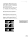
Editing Programs
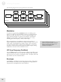
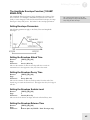
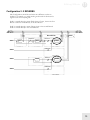
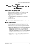
The following diagram shows the signal flow for each Sound:
LFO
LFO
LFO
Voice
Filter
Amp
Envelope
Envelope
Envelope
Range
Pan
Effects Sends
Sound 1
Sound 2
Sound 3
Sound 4
Modulation
In synthesizer programming, modulation refers to modifying some
aspect of a sound over time. Modulation is the key to making rich and
expressive sounds. The vibrato of a flute, the expression pedal of an
organ, and the wah pedal on a guitar are all examples of modulation.
Modulation can be used to control basic characteristics of a voice,
including pitch, filter frequency, volume, and envelope.
With some parameters, the modulation amount can be positive or
negative. With positive modulation for example, keyboard velocity can be
used to make a Sound brighter the harder you play. This is how many
acoustic instruments behave. With negative modulation, you also have
the ability to make the Sound more muted the harder you play. Setting
modulation to 00 turns off the modulation source.
LFO (Low Frequency Oscillator)
The term LFO stands for “Low Frequency Oscillator”. The LFO creates
a cyclic waveform that varies over time with a specified shape and speed.
This waveform can be used as a modulation source. The pitch, filter, and
amp modules each have a dedicated LFO.
Envelopes
An envelope is a modulation source that varies over time, starting from
when you strike a key. There are three independent envelope generators
(for pitch, filter, and amplitude) in each Sound layer.
34
NOTE: Modulation cannot force a
parameter beyond its maximum or minimum
value. For example, if the Amp is set to its
minimum value, applying negative
modulation will not affect it.
Editing Programs
7
Each envelope generator has the standard attack, decay, sustain, and
release parameters found on most synthesizers, along with delay, sustain
decay, and different triggering options. More on this later.
The Effects Section
The QS features a complete digital effects section with four input buses,
simultaneous multiple effects, and flexible signal routing. The effects
include Chorus, Flange, Detune, Delay, Reverb and EQ.
Effects parameters are edited separately from either the Program or the
Mix, using Effects Edit Mode. In Program Edit Mode, each of the four
Sounds in the Program has its own Effect Level control and can be
assigned to any one of the four effect buses.
Editing a Program
From Program Mode, press the [EDIT] button once.
NOTE: As soon as you change a value, the
word "EDIT" will change to "EDITED" in
the lower left part of the display.
Program Edit Functions
In Program Edit Mode, the numbered buttons select the Sound to edit or
the edit function. The function of the buttons is printed on the front
panel directly above or below the buttons.
Selecting a Sound to Edit [00-30 SOUND]
In Program Edit Mode, the [00]-[03] buttons select which Sound Layer
(1-4) you are editing. Remember, each Sound has its own sample,
amplifier, filter and envelope sections. You can change Sounds from any
Edit page by pressing a [00]-[03] button. Notice that the Sound number
changes in the upper left part of the display as you press these buttons.
35
7
Editing Programs
The Voice Function [40 VOICE]
Hit the [40] button to choose the sample that forms the basis of your
Sound. Use the [PAGE] buttons to select parameters within this
function to edit.
Turning Sounds On and Off
Button:
Page:
Parameter:
[EDIT] [40 VOICE]
1
Snd Enable (ON or OFF)
This enables or disables the selected sound. When a Sound is disabled,
“snd” will appear in lowercase in the display. When enabled, “SND” will
appear uppercase.
To avoid using up polyphony unnecessarily, turn off any Sounds that
you’re not using. Turning Sounds off is also a convenient way to isolate a
particular sound you are editing.
Selecting Keyboard or Drum Mode
Button:
[EDIT] [40 VOICE]
Page:
2
Parameter:
Snd Type (KYBD or DRUM)
This determines whether the Sound is in Keyboard Mode or Drum
Mode. This chapter describes the Keyboard Mode functions. See the
Drum Mode section of this manual for more information.
Selecting a Sample Category
Button:
[EDIT] [40 VOICE]
Page:
3
Parameter:
Group (see chart)
This selects the sample category (or group) for the Sound (for example,
Pianos, Organs, Guitars, etc.)
Selecting a Sample
Button:
[EDIT] [40 VOICE]
Page
4
Parameter:
Snd (see chart)
This selects the actual sample that will be the basis of the Sound. Here’s
a chart listing the various samples in their respective groups.
36
TIP: A quick way to turn a Sound on and off
from anywhere within Program Edit Mode is
to hold the corresponding Sound button
[00]–[30] and press [VALUE DOWN] to
disable or [VALUE UP] to enable.
Editing Programs
Group
7
Sample
GrndPianoL, GrndPianoR, DarkPno1 L, DarkPno1 R, DarkPno2 L, DarkPno2 R, DarkPno3 L,
Piano
DarkPno3 R, BritePno1L, BritePno1R, BritePno2L, BritePno2R, BritePno3L, BritePno3R,
4::VibesWave, NoHammer R, SoftPianoL, SoftPianoR, VeloPianoL, VeloPianoR, TapPiano L,
TapPiano R, E Spinet 1, E Spinet 2, Toy Pno L, Toy Pno R, KeyTrack1, KeyTrack2, Stretch L,
Stretch R, PianoWaveL, PianoWaveR, BriteRoads, Dark Roads, Soft Roads, VeloRoads1,
VeloRoads2, VeloRoads3, Wurly, VeloWurly1, VeloWurly2, FM Piano, FM Tines, Soft Tines,
VelAtkTine, Vel FM Pno, BrtRdsWave, DrkRdsWave, SftRdsWave, Wurly Wave
Chromatic Clavinet, VelAtkClav, ClavntWave, Harpsicord, VAtkHarpsi, HarpsiWave, Glock,
Xylophone, Marimba Hd, Marimba Sf, MarimbaVel, Vibraphone, VibesWave, Ice Block, Brake
Drum, TubulrWave, TubWv/Null, FMTblrBell, FMTublrSft, FMTublrVel, FMTub/Null
Rock Organ, Perc Organ, FullDrwbr1, FullDrwbr2, 3 Drawbars, 4 Drawbars, UpprDrwbrs,
Organ
16'Drawbar, 5 1/3' bar, 8' Drawbar, 4' Drawbar, 2 2/3' bar, 2' Drawbar, 1 3/5' bar, 1 1/3' bar,
1' Drawbar, Percus 2nd, Percus 3rd, Percus Wav, HollowWave, 60's Combo, RotarySpkr,
ChurchOrgn, Principale, Positive
SteelStrng, NylonGuitr, Nylon/Harm, Nylon/Harp, JazzGuitar, SingleCoil, Sngle/Mute,
Guitar
DoubleCoil, DCoil/Harm, DCoil/Jazz, D/S Coil, MicroGuitr, PwrH/MGtr1, PwrH/MGtr2,
MuteGuitar, Mute Velo, Metal Mute, MGtr/MtlMt, MtlMut/Hrm, Fuzz Wave, ClsHarmncs,
ElecHarmnc, Pwr Harm 1, Pwr Harm 2, Pwr Harm 3, PwrHrmVel1, PwrHrmVel2,
PwrHrmVel3
StudioBass, Studio&Hrm, Studio/Hrm, Slp/Studio, Slap Bass, Slap&Harm, Slap/Harm,
Bass
Slap/Pop, Pop/Slap, Bass Pop, Pop/Harm, Harm/Pop, JazzFingrd, Fingr&Harm, JazzPicked,
Pickd&Harm, Jazz Velo, Muted Bass, Stik Bass, Stik&Harm, Stik/Harm, Harm/Stik, Fretless,
Frtls&Harm, AcousBass1, AcoBs1&Hrm, AcousBass2, AcoBs2&Hrm, VelAcoBass, 3-VelBass1,
3-VelBass2, 3-VelBass3, 3-VelBass4, BassHarmnc
StringEnsm, TapeStrngs, SoloString, SoloViolin, Solo Viola, Solo Cello, Contrabass, Pizz Sectn,
String
Pizz Split, Pizz/Strng, Strng/Pizz, StringAttk, Harp, Hi Bow, Low Bow
Pop Brass, ClasclBras, AttakBrass, Trumpet, HarmonMute, Trombone, FrenchHorn, Bari
Brass
Horn, Tuba
Wdwind Bassoon, Oboe, EnglishHrn, Clarinet, Bari Sax, BrthyTenor, Alto Sax, SopranoSax, Velo Sax,
Flute, Flute Wave, Shakuhachi, PanPipe Hd, PanPipe Md, PanPipe Sf, PanPipeVel, Pan Wave,
BottleBlow, BottleWave
J Pad, M Pad, X Pad, Velo Pad 1, Velo Pad 2, Velo Pad 3, AcidSweep1, AcidSweep2,
Synth
AcidSweep3, AcidSweep4, AcidSweep5, VeloAcid 1, VeloAcid 2, VeloAcid 3, VeloAcid 4,
Chirp Rez1, Chirp Rez2, Chirp RezV, Quack Rez1, Quack Rez2, Quack Rez3, Quack Rez4,
QuackRezV1, QuackRezV2, QuackRezV3, Uni Rez 1, Uni Rez 2, Uni Rez 3, Uni Rez V,
AnalogSqr1, AnalogSqr2, AnalogSqrV, SyncLead 1, SyncLead 2, SyncLead V, Seq Bass, Seq
BassV1, Seq BassV2, FatSynBass, TranceBas1, TranceBas2, VeloTrance, FunkSynBs1,
FunkSynBs2, FunkSynBs3, FunkSynBsV, FilterBass, FM Bass, FM/FiltVel, Soft Chirp, Soft Rez
Pure Sine, 10% Pulse, 20% Pulse, 50% Pulse, Velo Pulse, Mini Saw, Saw Fltr 1, Saw Fltr 2, Saw
Wave
Fltr 3, Saw Fltr 4, Saw Fltr 5, Saw Fltr 6, Saw Fltr 7, RezSaw UK, RezSaw USA, Acid Saw, Velo
Saw 1, Velo Saw 2, Velo Saw 3, Velo Saw 4, Velo Saw 5, Velo Saw 6, AcidRezSqr,
VelAcidWav, MiniSquare, Sqr Fltr 1, Sqr Fltr 2, VeloSquare, Mini Tri, Tri Filter, Velo Tri,
Rectanglar, Hard Sync, HSync/Rect, BrightSync, Rez Sync, Ring Mod, RingMod V1, RingMod
V2, OctaveLock, Diet Saw, Band Saw, Notch Saw, HiPassSaw1, HiPassSaw2, HiPassSaw3,
HiPassSaw4, HiPassVel1, HiPassVel2, HiPassVel3, HiPassVel4, HiPassVel5, HiPassVel6,
Cognitive, Additive 1, Additive 2, VeloAdditv, Digital 1, Digital 2, Digital 3, Digital 4, Science
1, Science 2, Science 3, Science 4, VelScience, Metal Wave, Inharmonc1, Inharmonc2
WhiteNoise, Spectral, Crickets, Rain Noise, FiltrNoise, ShapeNoise, VeloNoise1, VeloNoise2,
Noise
VeloNoise3, NoiseLoop1, NoiseLoop2, NoiseLoop3, NoiseLoop4, NoiseLoop5
VocalAhhs, Soft Ahhs, Ahhs Wave, VocalOohs, Soft Oohs, Oohs/Ahhs, Ahhs/Oohs, Whistle,
Voice
Phonic
Sitar, Sitar Wave, Shamisen, Koto, DulcimerHd, DulcimerMd, DulcimerSf, DulcimrVel,
Ethnic
DulcmrWave, MandlnTrem, Accordian, Harmonica, Banjo, Kalimba, Steel Drum, Tuned Pipe
Stndrd Kit, Rock Kit 1, Rock Kit 2, Dance Kit, Brush Kit, ElctricKit, Tek Kit, Rap Kit, Street Kit,
Drums
MetalliKit, HvyMtliKit, VeloMtlKit, Trip Kit 1, Trip Kit 2, Trip Kit 3, Wild Kit, Octave Kit,
OrchstraKt, Raga Kit, FloppyKick, PillowKick, MasterKick, Metal Kick, Smoke Kick,
GrooveKik1, GrooveKik2, Sharp Kick, Tek Kick, AnalogKick, Rap Kick, FatWoodSnr, HR
Snare, Master Snr, PiccoloSnr, Electrnic1, Electrnic2, Rap Snare1, Rap Snare2, Tek Snare,
Brush Snr, Crosstick, Hi Tom, Mid Tom, Low Tom, Cannon Tom, Hex Tom, Rap Tom, Closed
Hat, HalfOpnHat, Open Hat, Foot Hat, TekHatClsd, TekHatOpen, RapHatClsd,
RapHatOpen, CricketCHH, CricketTIK, CricktsOHH, FltrNoisCH, FltrNoisOH, Ride Cym,
Ride Bell, Crash Cym, Null/Crash, Splash Cym, China Cym, Rap Cymbal, RapCymWave,
StndrdKtDM, RockKit1DM, RockKit2DM, DanceKitDM, BrushKitDM, ElctrcKtDM, Tek Kit
DM, Rap Kit DM, StreetKtDM, TripKit1DM, TripKit2DM, TripKit3DM, OctavKitDM,
OrchstraDM
37
7
Editing Programs
Percus
SndFX
Rhythm
Agogo, Bongo, Cabasa, Castanet, Chimes 1, Chimes 2, Chimes 3, Clap Rap, Clap Tek, Clave 1,
Clave 2, Conga Hit1, Conga Hit2, CongaSlap1, CongaSlap2, Rap Conga, Rap Rim, Cowbell,
RapCowbell, Cuica, Djembe Hi, Djembe Low, Drumstix, FingerSnap, GuiroLong1,
GuiroLong2, GuiroShort, Maracas, SmbaWhstl1, SmbaWhstl2, ShortWhstl, Shaker Hi, Shaker
Low, Sleighbel1, Sleighbel2, Tabla Ga, Tabla Ka, Tabla Ka 2, Tabla Na, Tabla Te, Tabla Te 2,
Tabla Tin, Taiko Drum, Taiko Rim, Talk Down, Talk Up, Tambourine, Timbale, Timpani,
Null/Timp, Triangle 1, Triangle 2, TrianglSf1, TrianglSf2, Udu Hi, Udu Mid, Udu Low, Udu
Slap, Vibrasmak1, Vibrasmak2, Wood Block
Rain 1, Rain 2, Bird Tweet, Bird Loop, Telephone, Jungle 1, Jungle 2, Jungle 3, Jungle 4,
GoatsNails, ScrtchPul1, ScrtchPul2, ScrtchPsh1, ScrtchPsh2, ScratchLp1, ScratchLp2,
ScrtchPLp1, ScrtchPLp2, ScrtchPLp3, ScrtchPLp4, Orch Hit, Null/Orch, Dance Hit,
Null/Dance, Rez Zip, RezAttack1, RezAttack2, RezAttkVel, Zap Attk 1, Zap Attk 2, Zap Attk
3, Fret Noise, Sci Loop 1, Sci Loop 2, Sci Loop 3, Bit Field1, Bit Field2, Bit Field3, Bit Field4, Bit
Field5, Bit Field6, WavLoop1.0, WavLoop1.1, WavLoop1.2, WavLoop1.3, WavLoop1.4,
WavLoop1.5, WavLoop1.6, WavLoop1.7, WavLoop1.8, WavLoop2.0, WavLoop2.1,
WavLoop2.2, WavLoop2.3, WavLoop2.4, WavLoop2.5, WavLoop2.6, WavLoop2.7,
WavLoop2.8, WavLoop3.0, WavLoop3.1, WavLoop3.2, WavLoop3.3, WavLoop3.4,
WavLoop3.5, WavLoop4.0, WavLoop4.1, WavLoop4.2, WavLoop4.3, WavLoop4.4,
WavLoop4.5, D-Scrape, D-ScrapeLp
Psi Beat 1, Psi Beat 2, Psi Beat 3, Psi Beat 4, Psi Beat 5, Psi Beat 6, Psi Beat 7, Psi Beat 8, Psi Beat
9, Psi Beat10, Psi Beat11, Psi Beat12, Kick Loop1, Kick Loop2, Kick Loop3, Kick Loop4, Kick
Loop5, Kick Loop6, Kick Loop7, Kick Loop8, Kick Loop9, KickLoop10, KickLoop11, Snare Lp
1, Snare Lp 2, Snare Lp 3, Snare Lp 4, Snare Lp 5, Snare Lp 6, Snare Lp 7, Snare Lp 8, Snare Lp
9, SnareBeat1, SnareBeat2, SnareBeat3, SnareBeat4, SnareBeat5, Back Beat1, Back Beat2, Back
Beat3, Back Beat4, Hat1 Clsd1, Hat1 Clsd2, Hat1 Foot, Hat1 Open1, Hat1 Open2, Hat2 Clsd1,
Hat2 Clsd2, Hat2 Foot, Hat2 Open1, Hat2 Open2, Hat3 Clsd1, Hat3 Clsd2, Hat3 Open1, Hat3
Open2, Hat Beat 1, Hat Beat 2, Hat Beat 3, Hat Beat 4, Hat Beat 5, Hat Beat 6, Hat Beat 7, Hat
Beat 8, Hat Beat 9, Hat Beat10, Agogo Loop, Bongo Loop, CabasaLoop, CastanetLp,
CongaLoop1, Shaker Lp1, Shaker Lp2, SleighLoop, Tabla Ga Lp, Tabla Ka Lp, Tabla Na Lp,
Tabla Te Lp, TablaTin Lp, Taiko Loop, PercBeat1, PercBeat2, PercBeat3, PercBeat4,
VoiceLoop1, VoiceLoop2, PhonicLoop, SpinalLoop, Tr Loop 1, Tri Loop 2, Orch Loop
The Level Function [50 LEVEL]
The Level function (button [50]) allows you to control the volume, pan
position, output assignment and effects send level for each Sound.
Setting the Sound Volume
Button:
[EDIT] [50 LEVEL]
Page:
1
Parameter:
Snd Volume (00 to 99)
This sets the volume for the current Sound.
Adjusting the Panning
Button:
[EDIT] [50 LEVEL]
Page:
2
Parameter:
Snd Panning (<3 to 3>)
This sets the panning over the stereo field, from far left (<3) to far right
(3>).
Routing Sounds to the Outputs
Button:
[EDIT] [50 LEVEL]
Page:
3
Parameter:
Snd Output (see below)
In the QS6.2, selecting ON routes the Sound to the main outputs; OFF
shuts off the path.
38
NOTE: If the Volume setting is “maxed
out” and you still can't hear anything, make
sure the Filter Frequency setting (described
later in this chapter) is greater than zero.
Editing Programs
In the QS8.2, selecting MAIN routes the Sound to the main outputs;
OFF shuts off the path. A setting of AUX will also shut off the path.
(This is provided for backward compatibility with older QS8 models).
7
TIP: Regardless of the setting, the Sound
may still feed an Effects Send.
Setting the FX Send Level
Button:
[EDIT] [50 LEVEL]
Page:
4
Parameter:
FX Level (00 to 99)
This determines how much the Sound feeds the chosen effects Send.
(See the “Editing Effects” section of this manual for more information).
Selecting the FX Send
Button:
[EDIT] [50 LEVEL]
Page:
5
Parameter:
FX Bus (1 to 4)
This selects which effects Bus or “Send” the Sound will feed. For
example, Send 1 may be a Chorus/Delay/Reverb, Send 2 may be Reverb
only, etc. (See the “Editing Effects” section of this manual for more
information).
The Pitch Function [60 PITCH]
The Pitch function (button [60]) lets you control the pitch aspects of
each Sound layer.
Setting the Pitch
Button:
[EDIT] [60 PITCH]
Page:
1
Parameter:
Semitone (-24 to +24 semitones)
This sets the oscillator pitch in semitones.
TIP: Remember, you can reset any
parameter back to its default value by
pressing the [VALUE UP] and [VALUE
DOWN] buttons at the same time.
Fine Tuning the Pitch
Button:
[EDIT] [60 PITCH]
Page:
2
Parameter:
Detune (-99 to +99 cents)
This sets the oscillator pitch in cents, from -99 (down 99/100 of a
semitone) to +99 (up 99/100 of a semitone).
Selecting the Detune Type
Button:
[EDIT] [60 PITCH]
Page:
3
Parameter:
DetuneType (NOR, EQU)
With NOR selected, the percentage of detuning remains the same over
the entire range of the keyboard, so the effects of detuning sound the
same no matter which key you play.
39
7
Editing Programs
With EQU selected, the absolute amount of detuning remains the same
over the entire keyboard, so any detuning seems less pronounced as you
play higher up on the keyboard.
Setting the Pitch Wheel Bend Amount
Button:
[EDIT] [60 PITCH]
Page:
4
Parameter:
PWHL>PITCH (0 to 12 semitones)
This sets the amount of pitch bend when the [PITCH] wheel is full
forward.
Setting the Aftertouch Pitch Bend Amount
Button:
[EDIT] [60 PITCH]
Page:
5
Parameter:
AFTCH>PITCH (-99 to +99)
This sets how much Aftertouch affects pitch. At +99, applying
aftertouch raises the pitch 5 semitones. At -99, it lowers the pitch 5
semitones.
NOTE: Aftertouch is not present on the
QS8.2 keyboard, but you can still have the
aftertouch effect when you control the QS8.2
via MIDI.
Setting the Pitch LFO Amount
Button:
[EDIT] [60 PITCH]
Page:
6
Parameter:
PLFO>PITCH (-99 to +99)
This sets how much the Pitch LFO affects pitch. Higher values increase
the amount of Pitch LFO modulation. Negative values flip the LFO
phase. Pitch LFO parameters (such as speed and wave shape) are
programmed within the Pitch LFO Function.
NOTE: Hearing a change when you edit
this parameter depends on whether the LFO
has received input from a modulator (such
as the Mod wheel). If you hear no change,
try moving the Mod wheel up.
Setting the Pitch Envelope Amount
Button:
[EDIT] [60 PITCH]
Page:
7
Parameter:
PENV>PITCH (-99 to +99)
This sets how much the Pitch Envelope affects Pitch. Higher values
increase the effect of the Pitch Envelope. Negative values turn the
envelope upside-down.
NOTE: Pitch Envelope parameters (such as
attack and decay time) are programmed
within the Pitch Envelope Function on
button [90].
40
Editing Programs
7
Setting the Portamento Mode
Button:
[EDIT] [60 PITCH]
Page:
8
Parameter:
Prtamento (EXPON, LNEAR, 1-SPD)
Portamento provides a glide in pitch from one note to the next. An
example of this is a steel guitar, where a note slides from one pitch to
another. This parameter determines the sweep’s curve.
With EXPON selected, the pitch change happens more rapidly at first,
then slows down as it approaches the destination pitch.
With LNEAR selected, the portamento glide time is constant. The pitch
takes the same time to reach its destination, regardless of the size of the
interval.
With 1-SPD selected, the portamento glide rate is constant, regardless of
the pitch difference between notes, so the pitch takes a longer time to
reach its destination for longer intervals.
Setting the Portamento Glide Time
Button:
[EDIT] [60 PITCH]
Page:
9
Parameter:
Porta Rate (00 to 99)
This sets the portamento glide time. Higher numbers give longer glide
times.
Setting Monophonic or Polyphonic Mode
NOTE: If a Sound layer’s Keyboard Mode
is set to MONO, the envelopes will only retrigger when playing legato if the Trigger
Mode is set to Reset or Reset-Freerun. For
more information on this, see the Envelope
Trigger functions.
Button:
[EDIT] [60 PITCH]
Page:
10
Parameter:
KeyMde (MONO, POLY, 1-PITCH or 1-PMONO)
In MONO mode, you can play only one note at a time. Portamento
behavior is most predictable in this mode.
TIP: With a feedback guitar patch that uses
one Sound for the guitar and another for the
feedback, set the feedback Sound to Mono to
insure that the feedback “whistle” will be
monophonic, which more accurately mimics
what happens in reality.
POLY mode allows you to play multiple notes at the same time.
In 1-PITCH mode, the program Sound layer will play a single pitch (the
sample used for note C3) throughout the entire keyboard range.
TIP: This is often used for layering in a
non-pitched noise or drum sound, for
example, to fatten up a bass guitar sound
with a hint of kick drum.
1-PMONO is simply a monophonic version of 1-PITCH.
The Filter Function [70 FILTER]
The Filter function (button [70]) lets you control the tone of each Sound
layer.
Setting the Filter Frequency
Button:
[EDIT] [70 FILTER]
Page:
1
Parameter:
Frequency (00 to 99)
This sets the filter frequency. Lower values give a duller sound; higher
values give a brighter sound. At 00, no sound will pass through the filter
(unless it is being positively modulated by another source). At 99,
TIP: Since the waveforms in the QS ROM
are recorded at the brightest possible
setting, filtering is often required to making
a program sound natural.
NOTE: This parameter interacts with
several others. If you hear no change when
you raise the Filter Frequency amount, try
lowering the F-ENV>FILT parameter.
41
7
Editing Programs
positive modulation won’t have any affect, since the filter is already
“maxed-out”.
Turning On Filter Keyboard Tracking
Button:
[EDIT] [70 FILTER]
Page:
2
Parameter:
Kbd Track (ON or OFF)
This sets how the filter frequency tracks across the keyboard.
When OFF, the filter frequency remains constant across the keyboard.
Higher notes will be more filtered than lower notes, since they have
higher frequency components.
When ON, the filter frequency will track the keyboard pitch. When you
play a higher note, the filter cutoff frequency will automatically be raised
to compensate for the higher note.
Setting Velocity Filter Tracking
Button:
[EDIT] [70 FILTER]
Page:
3
Parameter:
VELO>FILT (-99 to +99)
This sets how much keyboard velocity affects the filter frequency. At
positive values, playing harder raises the filter frequency, resulting in a
brighter sound. At negative values, playing harder lowers the filter
frequency, resulting in a darker sound.
Setting the Mod Wheel Filter Depth
TIP: Many acoustic instruments, such as
acoustic guitars, sound brighter when you
play them more forcefully. Adding a little
positive velocity control over the filter
frequency can more accurately simulate
these instruments.
NOTE: If you don’t hear any change when
you edit this and other filter parameters,
make sure the Filter Frequency is not
already “maxed-out”, i.e., it has room to
move in the direction you specified.
Button:
[EDIT] [70 FILTER]
Page:
4
Parameter:
MODWH>FILT (-99 to +99)
This sets how much the modulation wheel affects filter frequency. At
positive settings, moving the modulation wheel up raises the filter
frequency. At negative settings, moving the wheel up lowers the filter
frequency.
Setting the Aftertouch Filter Depth
Button:
[EDIT] [70 FILTER]
Page:
5
Parameter:
AFTCH>FILT (-99 to +99)
This sets how much aftertouch affects the filter frequency. At positive
values, applying aftertouch raises the filter frequency. At negative values,
applying aftertouch lowers the frequency.
Setting the Filter LFO Amount
Button:
[EDIT] [70 FILTER]
Page:
6
Parameter:
F-LFO>FILT (-99 to +99)
This sets how much the Filter LFO affects filter frequency. Higher
values increase the amount of filter LFO modulation. Negative values
flip the LFO phase.
42
TIP: Filter LFO is good for giving wah-wah
effects at slower LFO speeds, and for adding
“shimmering” at higher speeds.
NOTE: If you hear no change when you
alter this parameter, experiment with the
Filter LFO Functions on button [7]. You
may get a more pronounced effect if you use
a negative setting for Filter LFO Depth.
Editing Programs
7
Setting the Filter Envelope Amount
Button:
[EDIT] [70 FILTER]
Page:
7
Parameter:
F-ENV>FILT (-99 to +99)
This sets how much the Filter Envelope affects the filter frequency.
Higher values increase the effect of the Filter Envelope. Negative values
turn the envelope upside-down.
The Amp/Range Function [80 AMP/RANGE]
The Amp/Range function (button[80]) lets you control the velocity and
keyboard range of each Sound layer.
Selecting the Velocity Curve
Button:
[EDIT] [80 AMP/RANGE]
Page:
1
Parameter:
VelCrv (see chart)
This sets how the Level will respond to keyboard velocity.
TIP: Some of the Velocity Curves are
designed to be used in sets to allow a
different Sound to play depending on how
hard the keyboard is played.
LINEAR is the standard velocity curve, where playing harder results in a
louder sound. INVERTD is the opposite, where playing harder results
in a softer sound.
TIP: Most Sounds use the LINEAR velocity
curve.
1OF2XFD and 2OF2XFD stand for “1 Of 2 Crossfade” and “2 Of 2
Crossfade”. These are designed to be used in conjunction with each
other on two Sounds in the same Program, producing a “velocityswitching” effect (i.e., a different Sound will play depending on how hard
you hit the keys). 1OF2XFD is for the Sound that will be heard when
playing at lower velocities, while 2OF2XFD is for the Sound that will be
heard when playing at higher velocities. The curves are designed to cross
fade into each other to create a smooth transition between the two
sounds.
TIP: Many of the internal samples are
already "velocity-switching", meaning that
there is actually more than one sample per
note. These samples usually have “V” or
“Velo” in their names.
1OF3XFD, 2OF3XFD, and 3OF3XFD are designed to be used
together when you want to switch between three Sounds using velocity,
going from lower velocity to higher velocity.
1OF4XFD, 2OF4XFD, 3OF4XFD and 4OF4XFD are designed to be
used together when you want to switch between four Sounds using
velocity.
With a setting of MAXIMUM, the Sound will respond as if you are
playing at the maximum velocity at all times. With a setting of
MINIMUM, the Sound will respond as if you are playing at the
minimum velocity at all times.
Setting the Aftertouch Volume Depth
Button:
[EDIT] [80 AMP/RANGE]
Page:
2
Parameter:
AFTCH>AMP (-99 to +99)
This sets how much aftertouch affects the Sound level, or amplitude. At
positive values, applying aftertouch makes the sound louder. At negative
values, it makes the sound softer.
NOTE: Notes played at maximum velocity
might not have enough "headroom"
available for a positive aftertouch amplitude
swell. Try playing softly while
experimenting with this parameter.
43
7
Editing Programs
Setting the Amplitude LFO Amount
Button:
[EDIT] [80 AMP/RANGE]
Page:
3
Parameter:
A-LFO>AMP (-99 to +99)
This sets how much the Amplitude LFO affects the level. Higher values
increase the amount of amplitude LFO modulation. Negative values flip
the LFO phase.
NOTE: If you hear no change when you
alter this parameter, experiment with the
Amp LFO Functions on button [8]. You may
get a more pronounced effect if you use a
negative setting for Amp LFO Depth.
Setting the Lower Keyboard Limit
Button:
[EDIT] [80 AMP/RANGE]
Page:
4
Parameter:
LoLim (C2 000 to G8 127)
This specifies the lowest note of the Sound’s keyboard range. Each
Sound can be restricted to a specific range of the keyboard. This allows
you to create splits and layers across the keyboard.
TIP: You can set the upper or lower limit
when you're on these pages by holding [80]
and tapping a key on the keyboard.
Setting the Upper Keyboard Limit
Button:
[EDIT] [80 AMP/RANGE]
Page:
5
Parameter:
HiLim (C2 000 to G8 127)
This specifies the highest note of the Sound’s keyboard range.
Setting the Sound Overlap Amount
Button:
[EDIT] [80 AMP/RANGE]
Page:
6
Parameter:
Snd Overlap (00 to 99)
This determines how much notes of the same pitch are allowed to
overlap. This occurs if you hold the sustain pedal down and play the
same note over and over. When the value is set to 99, each voices is
allowed to play through to its entire release stage. At 00, the release stage
is shortened, cutting off previous notes.
The Pitch Envelope Function [90 PITCH
ENVELOPE]
The Pitch Envelope (button [90]) changes the pitch of a note over time.
It is typically used in special-effect synthesizer programs, but it may also
be used to simulate the characteristic of some instruments to go sharp
on the initial attack, when played hard. See below for the envelope
parameters.
The Filter Envelope Function [100 FILTER
ENVELOPE]
The Filter Envelope (button [100]) changes the tonal quality of a note
over time by controlling the filter frequency. For example, you can use it
to make the initial attack of a note bright and the sustaining part dark.
See below for the envelope parameters.
44
TIP: By setting the lower limit above the
high limit, you can create a “hole in the
middle” effect. This makes the Sound appear
to have two zones. All notes from the bottom
of the keyboard to the high limit note will
play, and all notes from the lower limit note
to the top of the keyboard will play.
NOTE: If you have Sound Overlap set to 99
and play the same note while holding the
sustain pedal, you will run through all 64
voices in no time. By adjusting the Sound
Overlap to a lower value, you ensure there
are voices available to play other sounds.
NOTE: The Pitch Envelope parameters will
have an effect only if the PITCH
ENVELOPE DEPTH (on Page 7 of the
PITCH function) is set to a value other than
0, or if Pitch Envelope is a source in the
MOD function.
NOTE: The Filter Envelope parameters will
have effect only if the FILTER ENVELOPE
DEPTH (on Page 7 of the FILTER function)
is set to a value other than 0, or Filter
Envelope is a source in the MOD function.
NOTE: The Filter Envelope may have no
effect if some other modulation source, or
the basic setting of the filter, has already
pushed the filter cutoff frequency to its
maximum
TIP: For the most effective Filter Envelope
sweeps, leave the Amplitude Envelope
Sustain level at maximum (99) and control
the shape of the Sound entirely with the
Filter envelope..
Editing Programs
7
The Amplitude Envelope Function [110 AMP
ENVELOPE]
The Amplitude Envelope (button [110]) determines the volume of the
note over time. For example, it determines whether the note fades in
slowly or starts abruptly. Unlike the Pitch and Filter Envelopes, the Amp
Envelope is always fully active. See below for the envelope parameters.
TIP: Some Programs may leave the Amp
Envelope fully open, and provide attack and
decay using the Filter Envelope.
Setting Envelope Parameters
The following parameters apply to the Pitch, Filter and Amplitude
Envelopes.
Setting the Envelope Attack Time
Buttons:
[EDIT] [90]-[110]
Page:
1
Parameter:
Attack (00 to 99)
This sets the amount of time the envelope will take to reach its
maximum level. The higher the value, the slower the attack.
Setting the Envelope Decay Time
Buttons:
[EDIT] [90]-[110]
Page:
2
Parameter:
Decay (00 to 99)
This sets the amount of time the envelope takes from the end of the
Attack stage to reach the Sustain level. The higher the value, the longer it
will take.
Setting the Envelope Sustain Level
Buttons:
[EDIT] [90]-[110]
Page:
3
Parameter:
Sustain (00 to 99)
This sets the level that the envelope will reach after the Decay time.
Setting the Envelope Release Time
Buttons:
Page:
Parameter:
[EDIT] [90]-[110]
4
Release (00 to 99, HOLD - Pitch Envelope only)
45
7
Editing Programs
This sets the amount of time the envelope will take to get from its
current level to zero after the note is released. The higher the value, the
longer it will take.
When set to HOLD, the Pitch Envelope will remain where it is after the
note is released.
Setting the Envelope Delay Time
Buttons:
[EDIT] [90]-[110]
Page:
5
Parameter:
Delay (00 to 99, HOLD)
This is the amount of time the envelope will wait before doing anything.
When the delay is set to zero, the envelope begins its attack right away.
When set to HOLD, the Delay stage of the envelope will wait until the
key is released before running through the remaining envelope stages. In
addition, the Envelope’s Trigger behavior will be automatically set to
FREERUN (see below). The displayed value of that parameter is not
changed; only its behavior is.
Setting the Envelope Sustain Decay Time
Buttons:
[EDIT] [90]-[110]
Page:
6
Parameter:
Sus Decay (00 to 99)
This sets the amount of time the envelope will take during the sustain
stage to go down to zero. If this is set to 99, the envelope will remain at
the Sustain level until the note is released. When set to 00, the envelope’s
level will immediately jump to 0 upon reaching the sustain stage.
Setting the Envelope Trigger Type
Buttons:
[EDIT] [90]-[110]
Page:
7
Parameter:
Trig (NORMAL, FREERUN, RESET, RES-FRE)
This determines how the envelope will start and stop based on how the
keys are held and released.
When set to NORMAL, the envelope will play from the attack stage
through to the sustain stage as long as the note is held. When the note is
released, the envelope will jump to its release stage.
When set to FREERUN, the envelope will complete its entire cycle,
even if the note is released before the envelope has completed its cycle.
When set to RESET, the envelope will start at the beginning whenever a
new note is played.
When set to RESET-FREERUN, the envelope will start at the
beginning whenever a new note is played and it will complete its entire
cycle, even if the note is released in the middle.
46
NOTE: In NORMAL and FREERUN modes,
when a voice is stolen by a new note, the
envelope will not start from the beginning,
but will continue from its current level.
TIP: If you don’t want the envelope to retrigger when playing legato, set the
Keyboard Mode to MONO and the envelope
trigger mode to NORMAL.
TIP: To get the most natural-sounding
Sustain Pedal reaction, the best setting for
the Filter Envelope Trigger Mode is usually
either the FREERUN or the RESETFREERUN mode. This allows the Filter to
keep following its envelope shape even after
the keys are lifted up.
Editing Programs
7
Activating Envelope Key Tracking
Buttons:
[EDIT] [90]-[110]
Page:
8
Parameter:
Time Track (ON or OFF)
This determines whether keyboard position affects the speed of the
envelope. When ON, playing toward the higher end of the keyboard will
result in a faster envelope cycle.
This only affects the decay, sustain decay and release segments of the
envelope. The envelope’s timing doubles or halves over a range of two
octaves.
Activating the Sustain Pedal
Buttons:
[EDIT] [90]-[110]
Page:
9
Parameter:
SustainPed (ON or OFF)
This determines whether the Sustain Pedal will affect the envelope.
Setting the Envelope Level
Buttons:
[EDIT] [90]-[110]
Page:
10
Parameter:
Env Level (00 to 99)
This sets the level of the envelope. At 99 the envelope will have a
maximum effect on whatever it is being routed to.
NOTE: If the Env Level is already at 99, a
positive value for VEL>Level will have no
effect because it is already “maxed-out”. To
hear the full effect, the sum of the Env Level
and VEL>Level values should not exceed
99.
Setting Velocity Modulation of the Envelope
Buttons:
[EDIT] [90]-[100]
Page:
11
Parameter:
VEL>Level (00 to 99)
It determines how keyboard velocity will affect the Pitch or Filter
envelope level. When set to 99, notes played hard will deliver a higher
envelope output than notes played soft.
NOTE: This setting is not available on the
Amplitude Envelope because there is a more
specific velocity curve setting in the
AMP/RANGE function.
Naming the Program [120 NAME]
The Name function (button [120]) allows you to change the Program’s
name. Use the [PAGE] buttons to position the cursor. Here is a chart of
available characters:
4
H
¥
p
!
5
I
]
q
"
6
J
^
r
#
7
K
_
s
$
8
L
`
t
%
9
M
a
u
&
:
N
b
v
’
;
O
c
w
(
<
P
d
x
)
=
Q
e
y
*
>
R
f
z
+
?
S
g
{
,
@
T
h
|
A
U
i
}
.
B
V
j
>
/
C
W
k
<
0
D
X
l
1
E
Y
m
2
F
Z
n
3
G
[
o
47
7
Editing Programs
Copying Sound Layers [STORE]
While editing a Program, it is helpful to be able to copy a Sound layer to
another Sound in either the same Program or a different Program,
especially if you are building a split or layered Program. Here’s how:
1 ) From Program Edit mode, press [STORE].
2 ) Press [PAGE >] once to select the Copy Sound function.
3 ) Use the [VALUE] buttons to select the source for the copy. You
can choose either a Sound in the current Program, or different
Program. (If you choose a different Program, the Sound layer to be
copied will be determined by your destination choice).
4 ) Press [PAGE >] again to advance the cursor to the lower line of the
display.
5 ) Use the [VALUE] buttons to choose a destination. Depending on
the choice you made in step 3, you will be able to choose either a
Sound layer, or a Program number.
If you selected a Program number in the top line, you’ll only be able
to select Sounds 1-4 as the destination Sound. Keep in mind that
your choice here will also determine which Sound will be copied
from the Program number you chose in the top line.
If you selected one of the current Program’s four Sounds in the top
line, you’ll be able to select any of the other three Sounds in the
current Program or one of the Programs in the User Bank (000127). The Sound number in the top line determines the target
Sound within the User Program you chose.
6 ) Press [STORE] to copy the Sound.
Auditioning Programs Before Storing
When it’s time to store your Program, you may need to “look around” to
find a Program that you don’t need anymore so you can overwrite it.
To do this, you can take advantage of the fact that you can move
between Program Mode and Mix Mode without losing your changes. So,
to find a new location to store your edited Program, jump into Mix
Mode, search for a Program you can overwrite there, then jump back into
Program Mode and store the Program.
48
NOTE: The way to tell the difference
between a program edited in Program Mode
and one edited from Mix Mode is by looking
at the display: in Program Edit Mode,
“PROG EDIT” appears in the lower-left
corner of the display, while in Mix Program
Edit Mode, “MIXPROG EDIT” appears.
8 Modulations
The Mod Routes
As we mentioned in the previous chapter, modulation refers to
modifying some aspect of a sound. For example, sound volume is
shaped (or modulated) by the Amplitude Envelope. A Mod Route
refers to a modulation source and the destination that it is modulating.
In the previous chapter, we’ve already covered some of the “hard wired”
mod routes. One example is the Pitch LFO, which can always be used to
modulate pitch. In addition however, there are six general-purpose mod
routes that have many more possible mod sources and destinations.
Using these, you can:
• Use a slider to control brightness, effect level, LFO speed, etc.
• Use velocity to increase the attack speed of an envelope, so playing
softly makes the sound fade in, while playing hard causes an immediate
attack.
• Use release velocity to decrease the release time of an envelope, so
quick releases of the keys cut off the end of the sound, while slow key
releases allow the sound to fade away gradually.
Hard Wired Mod Routes
One way to extend the power of your Mod section is to be sure you're
not routing something with a Mod that could be handled elsewhere in
the QS's functions. Here's a list of routings that are "hard wired" into
the QS:
Source
Aftertouch
Amplitude LFO
Filter Envelope
Filter LFO
Mod Wheel
Note Number
Pitch Envelope
Pitch LFO
Pitch Wheel
Velocity
Destination
Amplitude
Amplitude LFO Depth
Filter Frequency
Filter LFO Depth
Pitch
Pitch LFO Depth
Amplitude
Filter Frequency
Filter Frequency
Amplitude LFO Depth
Filter Frequency
Filter LFO Depth
Pitch LFO Depth
Envelope Time Tracking
Filter Frequency
Pitch
Pitch
Pitch
Filter Envelope Level
Filter Frequency
Pitch Envelope Level
Button
[80 AMP/RANGE]
[8 AMP LFO]
[70 FILTER]
[7 FILTER LFO]
[60 PITCH]
[6 PITCH LFO]
[8 AMP LFO]
[100 FILTER ENV]
[7 FILTER FREQ]
[8 AMP LFO]
[70 FILTER]
[7 FILTER LFO]
[6 PITCH LFO]
[90-110 P/F/AENV]
[70 FILTER]
[90 PITCH ENV]
[6 PITCH LFO]
[60 PITCH]
[100 FILTER ENV]
[70 FILTER]
[90 PITCH ENV]
Page
2
7
5
7
5
7
5
10
5
6
4
6
6
8
2
10
5
4
11
3
11
49
8
Modulations
Editing the Mod Routes
The Mod Routes are part of each Program, just like any other program
parameter (like Filter Frequency for example). Hit [EDIT] from
Program mode to begin editing.
Selecting a Mod Route [0-5 MOD]
In Program Edit Mode, use the [0] - [5] buttons to select one of the six
mod routes to edit. All modulators work in the same way, so only the
pages of one will be described here.
When you’re in one of the Mod pages, the top line of the display will
show whether that Mod is active. If the Mod is disabled (Level set to 00),
“mod” will be in small letters. If the Mod is enabled, “MOD” will be
capitalized.
Choosing the Mod Source
Buttons:
[EDIT] [0-5 MOD]
Page:
1
Parameter:
Src (see below)
Here, you can select one of the following modulation sources:
• NOTE # provides a modulation signal that corresponds to the note
played on the keyboard (higher keys give higher values).
• VELOCITY refers to how hard you hit the keys.
• REL VEL (Release Velocity) refers to how fast you let go of the keys.
• AFT TCH (Aftertouch) Pressing on the keys after they’re down
generates this control signal. This represents an average of all keys
being pressed. The harder you press on the keys, the greater the degree
of modulation. (Note, the QS8.2’s keyboard does not generate
aftertouch, but the synthesizer can still respond to MIDI aftertouch
messages).
• POLYPRES (Polyphonic Pressure) is similar to aftertouch, but each
key can respond to individual pressure messages. Although the QS’s
keyboard does not generate poly pressure, its sound generators can
respond to MIDI poly pressure messages.
• MOD WHL (Modulation Wheel) is traditionally assigned to LFO
level so that rotating the wheel away from you introduces vibrato.
However it is also well-suited for controlling timbre, vibrato speed,
and other parameters.
• PITCH WH (Pitch Wheel) usually controls the oscillator pitch but
can control other parameters.
• MIDI VOL corresponds to MIDI controller #7. Example: Assign the
filter cutoff as the destination, and you can have the signal become
less bright as it becomes lower in volume.
• SUST PED (Sustain Pedal) The sustain pedal plugged into the sustain
pedal jack provides this modulation signal.
• PEDAL 1: A controller pedal plugged into the [PEDAL 1] jack
provides this modulation source. The default setting assigns Pedal 1 to
MIDI Controller 7 to act as a volume pedal. But it can also be assigned
to any other incoming MIDI controller number in Global page 12.
50
Modulations
• PEDAL 2: Although there is no Pedal 2 jack on the QS, it is available
as a modulation source via MIDI controller messages. The Pedal 2
modulation source defaults to MIDI Controller #4 (Standard Foot
Controller). It is possible to assign it to a different controller number
if you wish on Global Mode, page 13.
• PLFO/FLFO/ALFO: You can select the Pitch, Filter and
Amplitude LFOs as modulation sources, even if they aren't being used
to affect the Sound in their usual ways.
• PENV/FENV/AENV: The Pitch, Filter and Amplitude envelopes
can also be selected as modulation sources. Try routing them to LFO
speeds or the Effect Send Level of a Sound.
• RANDOM: This provides a different modulation value every time
you hit a key. Example: With vintage analog synth patches, use pitch as
the destination and apply a very slight amount of random modulation.
Each note will have a slightly different pitch, which simulates the
natural tuning instability of analog circuits.
• TRIGATE: This is the Trigger Rate Follower, which monitors how
fast notes are being played on the keyboard. For example, if routed to
the Effect send of a Program, you could automatically have more
effect when playing quickly, and less effect when playing slowly.
• CNTRL (A, B, C, D): These are the four [CONTROLLER] sliders
on the front panel. Since these sliders also have MIDI controller
numbers assigned to them, they can be remotely controlled via MIDI.
The MIDI controller numbers are assigned in Global page 8-11.
• TRACKGEN: This is the output of a signal processed by the
Tracking Generator module.
• STEPTRAK: This is the output of a signal processed by the
Tracking Generator module in stepped mode.
Choosing the Mod Destination
8
TIP: If you want to modulate the pitch or
filter Envelope Level positively, set the
Envelope Level to zero so you have room to
modulate. For the amplitude envelope, set
the level to 01. Similarly, if you want to
modulate any Envelope Level negatively, set
the Envelope Level to 99.
NOTE: When negatively modulating the
amplitude envelope, make sure the negative
modulation amount is not greater than the
Aenv Level setting. For example: If your
Aenv Level is at 59 and you have Controller
A routed to AENV AMP with a mod amount
of -60, any note held down when Controller
A reaches its maximum throw will be
considered “off” and will be unable to be
pulled back up by Controller A. You'll have
to re-trigger the note.
Buttons:
[EDIT] [0-5 MOD]
Page:
2
NOTE: When Portamento Rate is chosen as
Parameter:
Dst (see below)
a destination, you will hear no change in
that parameter unless it is at least set to 01.
Here, you can select from the following modulation destinations. You
can find out more about these parameters and how they affect the sound
in their respective sections:
• Pitch
• Filter LFO Speed
• Amp Envelope Delay
• Filter Frequency
• Filter LFO Amp
• Amp Envelope Attack
• Amplitude
• Filter LFO Delay
• Amp Envelope Decay
• Effect Send
• Filter Envelope Delay
• Amp Envelope Sus. Decay
• Pitch LFO Speed
• Filter Envelope Attack
• Amp Envelope Release
• Pitch LFO Amp
• Filter Envelope Decay
• Amp Envelope Amp
• Pitch LFO Delay
• Filter Envelope Sus. Decay
• Portamento Rate
• Pitch Envelope Delay
• Filter Envelope Release
• Pitch Envelope Attack
• Filter Envelope Amp
• Pitch Envelope Decay
• Amp LFO Speed
• Pitch Envelope Sus. Decay
• Amp LFO Amp
• Pitch Envelope Release
• Amp LFO Delay
• Pitch Envelope Amp
51
8
Modulations
Setting the Mod Level
Buttons:
[EDIT] [0-5 MOD]
Page:
3
Parameter:
Level (-99 to +99)
This sets the modulation level. At zero, the modulation source has no
effect on the destination (it is disabled). Higher positive values increase
the amount of modulation in the positive direction. Negative values
increase the amount of modulation in the negative direction.
In other words, if you choose Controller A as your source and Pitch as
your destination, a value here of +99 will cause the pitch to rise as slider
A moves up. A value of -99 will lower the pitch as slider A moves up.
NOTE: When modulating Pitch, a Mod level
of +72 or - 72 will give exactly one octave of
modulation at maximum input.
Turning On the Mod Gate
Buttons:
[EDIT] [0-5 MOD]
Page:
4 (Mods 1-3 only)
Parameter:
Gated (ON or OFF)
This determines whether the modulator will be active after keys are
released. When the gate is ON, the Modulator will only be active while
notes are being held. The effect of the Modulator will stop when you are
not playing any notes. This function is available only in mod routes 1
through 3.
TIP: This can be used on sounds with long
release times, where an effect (like tremolo)
is intended to be active while holding notes
down, but deactivated as the sound is fading
away after being released. Or if you're using
the Sustain pedal, you can have vibrato
present until the keys are released.
Turning On Quantization
Buttons:
[EDIT] [0-5 MOD]
Page:
4 (Mods 4-6 only)
Parameter:
Quant (ON or OFF)
This determines whether the modulator will modulate in a smooth
fashion, or a stepped (quantized) fashion. When it is ON, the
modulation effect will be stepped. When OFF, the effect will be smooth.
This function is only available in mod routes 4 through 6.
The Pitch LFO Function [6 PITCH LFO]
The Pitch LFO function is most often used to apply vibrato to a Sound.
See below for the LFO parameters.
The Filter LFO Function [7 FILTER LFO]
The Filter LFO function is most often used to apply tremolo-like or
"wah-wah" effects to a sound. See below for the LFO parameters.
TIP: If the Modulation Wheel is routed to
Pitch with an amplitude of +99, moving the
Mod Wheel with the Quantize parameter ON
will cause the pitch to rise in half-step
increments.
NOTE: The Pitch LFO parameters will
make a difference in the sound only if the
PITCH LFO DEPTH (on Page 6 of the
PITCH function) is set to a value other than
0, or, if the Pitch LFO is a source in the
MOD function.
NOTE: The Filter LFO parameters will
affect the sound only if the FILTER LFO
DEPTH (on Page 6 of the FILTER function)
is set to a value other than 0 , or,if Filter
LFO is a source in the MOD function.
The Amplitude LFO Function [8 AMP LFO]
The Amp LFO function is usually used to add tremolo to a sound. See
below for the LFO parameters.
Setting LFO Parameters
The following parameters apply to the Pitch, Filter and Amplitude LFOs
described above.
52
NOTE: The Amp LFO parameters will have
an effect only if the AMP LFO DEPTH (on
page 3 of the AMP/RANGE function) is set
to a value other than 0, or if Amp LFO is a
source in the MOD function.
Modulations
8
Selecting the LFO Waveform
Buttons:
[EDIT] [6-8]
Page:
1
Parameter:
Wave (8 choices)
The waveform determines the shape of the LFO. Note that the two
Sawtooth waves, the Square and the Random+ waves are unipolar
(positive-going only) and the rest are bipolar (positive and negative
going):
SINE
TRIANGLE
SINE
DOWN SAW
DOWN SA
TRIANGLE
W
RANDOM+-
RANDOM+-
SQUARE
TIP: The "unipolar" (positive-going)
waveshapes tend to have a more noticeable
impact on Filter and Amplitude if they are
routed negatively.
SQUARE
NOISE
NOISE
UP SAW
UP SA
RANDOM+
W
RANDOM+
Setting the LFO Speed
Buttons:
[EDIT] [6-8]
Page:
2
Parameter:
Speed (00 to 99)
This controls the speed of the LFO. The higher the value, the faster the
waveform.
Setting the LFO Delay
Buttons:
[EDIT] [6-8]
Page:
3
Parameter:
Delay (00 to 99)
This sets the amount of time it takes the LFO to fade in from no
modulation to maximum modulation. The higher the value, the more
slowly the LFO fades in.
Setting the Trigger Type
Buttons:
[EDIT] [6-8]
Page:
4
Parameter:
Trigger
Range:
MONO, POLY, KEYMONO, or KEYPOLY
This determines how each voice’s LFO should be started. When playing
multiple voices in a single Sound, each voice has its own LFO. The
Trigger parameter determines whether or not they should be in sync, and
whether or not they can be re-triggered independently from one another.
NOTE: Some modulation sources are by
their very nature polyphonic (for example,
velocity or envelope). You will be allowed
to set up such Mod routings when the
Trigger mode is set to MONO, but you won’t
hear any modulation of the LFO speed
occur.
53
8
Modulations
MONO. All voices’ LFOs will be in sync with each other.
POLY. Each voice’s LFO is independent. If you hold a chord, some
voices’ LFOs will be moving in one direction while others move in the
other direction. If the LFO Speed is being modulated (by one of the
envelopes, for example), the LFOs of each voice may be running at
different speeds.
KEYMONO. This is identical to MONO, but whenever a new note is
played, the LFO is re-triggered, instead of continuing from wherever it
may be in its cycle.
KEYPOLY. This is identical to POLY, but whenever a new note is
played, the LFO is re-triggered, instead of continuing from wherever it
may be in its cycle.
Setting the LFO Level
Buttons:
[EDIT] [6-8]
Page:
5
Parameter:
Level (00 to 99)
This is the base output level of the LFO. If you want to have a constant
value of vibrato, even without using the Mod Wheel or Aftertouch, set
LEVEL above 00. The Mod Wheel and Aftertouch can add to or
subtract from this base level.
NOTE: For example, if Level is set to 10
and the Mod Wheel parameter (see the next
parameter) is set to 10, there will always be
some vibrato, and raising the Mod Wheel
will add more vibrato. On the other hand, if
the Mod Wheel parameter is set to -10,
raising the Mod Wheel to the top will cancel
out all vibrato.
Mod Wheel LFO Depth
Buttons:
[EDIT] [6-8]
Page:
6
Parameter:
MODWH>LFO (-99 to +99)
This sets how much the Mod Wheel will increase or decrease the LFO’s
Level. A positive value raises the level when the Mod Wheel is moved
up. Negative values will lower the level of the LFO as the Mod Wheel is
raised.
Aftertouch LFO Depth
Buttons:
[EDIT] [6-8]
Page:
7
Parameter:
AFTCH>LFO (-99 to +99)
This parameter sets how much the Aftertouch will increase or decrease
the LFO’s Level. A positive value raises the level as more Aftertouch is
applied. A negative value lowers the level as more Aftertouch is applied.
Scaling Modulation Sources [9 TRACK GEN]
The Tracking Generator (TG) is used to scale a modulation source. For
example, normally you could modulate the volume of a sound using
velocity; the harder you play, the louder the sound gets. The amount of
change in volume is equal to the change in velocity; this is called linear
control. If instead, however, you set the Tracking Generator’s input to
“velocity”, and then routed the Tracking Generator to the Amp (using
the Mod function), you can make your own customized velocity curve!
54
NOTE: Since the output level of the LFO
cannot be less than zero, a negative setting
of the Mod Wheel parameter will have no
effect unless there is LFO already occurring.
Modulations
8
It might be helpful to think of the Tracking Generator as a fifth page
available to the Mod function. When you choose it as your source on the
first page of a Mod (let's say button [0], or Mod 1), you then need to go
select the TG's input on button [9], page 1. In effect, the TG's input is its
"Mod source", and the TG itself becomes a sort of "Mod destination".
Modulation input is basically filtered through the TG before it reaches
the actual Mod destination on page 2 of Mod 1.
The Tracking Generator divides the range of the input into 11 points (010), each of which can be set between 0 and 100. If you boost the value
of one of the lower points, you make the input more sensitive in its
lower register. By creating a non-linear curve using the velocity example
above, you can scale the velocity’s control over the sound’s volume just
the way you want.
When selecting the Tracking Generator as a modulation source in the
Mod Function, two choices will be available (TRACKGEN and
STEPTRAK). When TRACKGEN is selected as the modulation source,
the Tracking Generator functions normally, scaling its input as
determined by its parameter settings.
When STEPTRAK is selected as a modulation source, the Tracking
Generator’s output will be stepped, or interpolated. This means that
instead of scaling the input in a linear fashion from point to point, the
input is kept at each point’s value setting until it goes beyond the
following point’s value setting, at which point it jumps to that setting.
This feature is very useful in creating “mini-sequences” if the modulation
destination is set to PITCH and the Tracking Generator’s input is an
LFO using an “Up Sawtooth” as its waveform. The HipHop and
EuroDance QCards contain many examples of this extremely cool usage
of the Tracking Generator.
LINEAR TRACKGEN
LINEAR
TIP: The Tracking Generator can be used
to turn a variable control, such as the Mod
Wheel or velocity, into a switch by setting all
of the points to 0 except for point 10. Only
near the maximum input will anything other
than 0 come out of the Tracking generator.
100
0
POINTS:
0
1
2
3
4
5
6
7
8
9
10
9
10
9
10
NON-LINEAR TRACKGEN
NON-LINEAR
100
0
POINTS:
0
1
2
3
4
5
6
7
8
NON-LINEAR STEPTRACK
NON-LINEAR STEPPED
100
0
POINTS:
0
1
2
3
4
5
6
7
8
55
8
Modulations
Selecting the Tracking Generator Input
Button:
[EDIT] [9 TRACK GEN]
Page:
1
Parameter:
Input (see below)
Select the input of the Tracking Generator from the following sources:
•
•
•
•
•
Note Number
Velocity
Release Velocity
Aftertouch
Poly Pressure
•
•
•
•
•
Mod Wheel
Pitch Wheel
MIDI Volume
Sustain Pedal
Pedal 1
•
•
•
•
•
Pedal 2
Pitch LFO
Filter LFO
Amp LFO
Pitch Envelope
•
•
•
•
•
Filter Envelope
Amp Envelope
Random
Trig Rate
Controllers A–D
For detailed descriptions of each of these sources, see the section
“Modulation Source” in the Mod section.
Setting a Tracking Point
Button:
[EDIT] [9 TRACK GEN]
Pages:
2-12 (for points 0-10)
Parameter:
Input (00 to 100)
The remaining pages of the TRACK GEN function control the levels of
the tracking points 0-10. Select the various Points with the [PAGE]
buttons, and change the values in the usual ways. A higher number
increases the impact that Point will have on whatever the Mod
destination is.
56
TIP: You can create your own custom
velocity curves using the Tracking
Generator and the Mod section. It's easier
to do this if you start with the MINIMUM
velocity curve (under the [AMP/RANGE]
function). Then select an available Mod
(say Mod 1), and on page 1 select
TRACKGEN as your source. On page 2
select Amplitude as your destination, and
then set the level to +99 on page 3. On
button [9], page 1, select Velocity as your
Input and then experiment with the ways
different numbers affect the velocity
response as you input values for Points 0-10.
9 Editing Drum Kits
Drum Mode
Drum Mode allows you to construct your own drum kits within a
Program. Any one or all of the four Sound layers in a Program can be
put into Drum Mode.
In Drum Mode, you can select 10 drum samples per Sound and
individually control their pitch, level, panning, effects routings, and
placement on the keyboard. You can choose from a collection of 343
samples: 21 kicks, 26 snares, 33 toms, 43 cymbals, 75 percussion
instruments, 82 sound effects and 63 synth waves. Plus, there are 90
rhythm beats to choose from (pre-sequenced drum loops). If all four
Sounds in a Program were placed in Drum Mode, you could assemble up
to 40 tailor-made drum sounds in your kit. To round things out,
individual drums can be stretched to occupy up to four consecutive keys
without transposing (for more realistic flams).
Editing in Drum Mode
To edit a sound in Drum Mode, start from Program mode and hit
[EDIT]. Select a Sound layer by pressing one of the [00] through [30]
buttons.
Next, hit [40 VOICE] and page over to the Snd Type parameter (page 2).
Use the [VALUE] buttons to select DRUM for the sound type.
Notice that the “SND1” text in the upper left corner changes to “S1D1”,
indicating that you’re editing Sound layer 1, Drum 1 in Drum Mode (or
whichever Sound layer you selected).
Selecting a Drum to Edit [0-9 DRUM]
The [0] - [9] buttons are used to select a Drum (1-10) to edit. You can
select which Drum you are editing at any time, from any display page in
Drum Edit Mode.
NOTE: When Drum Mode is enabled, the
Sound will have fewer parameters for
editing. Consequently, not all Function
buttons will respond when pressed as they
do when the Sound is in Keyboard mode.
Specifically, the LFOs and all Envelopes
(with the exception of the Amp Envelope) are
unavailable. In addition, the parameters in
most other functions will differ.
TIP: Here’s a quick way to select the Drum
you’d like to edit: If it is on Sound 1, hold
down the [00] button and hit the key the
Drum is on. If the Drum is on Sound 3, use
the [20] button and hit the key.
Selecting the Drum Sample [40 VOICE]
The Voice function (button [40]) is where you choose the particular
sample for the selected Drum (1-10). Similar to the normal Assign Voice
function, sounds are divided into groups. After selecting the group (on
display page 3), you then select the sample within the group (on page 4).
57
9
Editing Drum Kits
Here is a chart listing the various drum samples in their respective groups.
Group
Kick
Snare
Toms
Cymbal
Percus
Snd FX
Wave
Rhythm
58
Voice
FloppyKik1, FloppyKik2, FloppyKikV, MasterKik1, MasterKik2, MasterKikV, MetalKick1,
MetalKick2, MetalKickV, GrooveKik1, GrooveKik2, GrooveKikV, Sharp Kick, Tek Kick 1, Tek
Kick 2, Tek Kick V, AnalogKik1, AnalogKik2, AnalogKik3, AnalogKikV, Rap Kick
Fat Wood 1, Fat Wood 2, Fat Wood V, HR Snare 1, HR Snare 2, HR Snare V, MasterSnr1,
MasterSnr2, MasterSnrV, Piccolo 1, Piccolo 2, Piccolo V, Electronc1, Electronc2, ElectroncV, Rap
Snare1, Rap Snare2, Tek Snare1, Tek Snare2, Tek SnareV, Brush Hit1, Brush Hit2, Brush HitV,
Crosstick1, Crosstick2, CrosstickV
HiRackTom1, HiRackTom2, HiRackTomV, MdRackTom1, MdRackTom2, MdRackTomV,
LoRackTom1, LoRackTom2, LoRackTomV, HiFlrTom 1, HiFlrTom 2, HiFlrTom V, MidFlrTom 1,
MidFlrTom 2, MidFlrTom V, LowFlrTom1, LowFlrTom2, LowFlrTomV, CanonTomH1,
CanonTomH2, CanonTomHV, CanonTomM1, CanonTomM2, CanonTomMV, CanonTomL1,
CanonTomL2, CanonTomLV, Hex Tom Hi, Hex Tom Md, Hex Tom Lo, RapTomHi,
RapTomMid, RapTomLow
ClosedHat1, ClosedHat2, ClosedHatV, Tight Hat, Loose Hat, Slosh Hat, Foot Hat 1, Foot Hat 2,
Velo Hat 1, Velo Hat 2, Velo Hat 3, TekHatClsd, TekHatOpen, RapHatClsd, RapHatHalf,
RapHatOpen, CricktHat1, CricktHat2, FilterHat1, FilterHat2, FilterHat3, Ride Cym, Ride Cym 2,
RideCym V1, RideCym V2, RideBell 1, RideBell 2, RideBell V, Crash Cym1, Crash Cym2,
SplashCym1, SplashCym2, SplashCym3, China Cym1, China Cym2, RapCymbal1, RapCymbal2,
RapCymWave, Open Hat 1 , Open Hat 2 , Open Hat 3 , Open Hat V , RideCym V3
Agogo Hi, Agogo Low, Bongo Hi, Bongo Low, Brake Drum, Cabasa, Castanet, Chimes 1,
Chimes 2, Clap Rap, Clap Tek, Clave, Conga Hi, Conga Low, Conga Slap, RapCongaHi,
RapCongaMd, RapCongaLo, Rap Rim, Rap Tone, Cowbell, RapCowbell, Cuica, Djembe Hi,
Djembe Low, Drumstix, FingerSnap, Guiro Long, Guiro Med, GuiroShort, Ice Block, Kalimba Hi,
KalimbaLow, Maracas, SambaWhstl, SambaShort, Shaker1 Hi, Shaker1Low, Shaker2 Hi,
Shaker2Low, Sleighbl 1, Sleighbl 2, SteelDrmHi, SteelDrmLo, TablaGa Hi, TablaGaLow, Tabla
Ka, TablaNa Hi, TablaNaLow, Tabla Te, TablaTinHi, TablaTinLo, Taiko Hi, Taiko Low, Taiko
Rim, Talk Up Hi, Talk Up Lo, TalkDownHi, TalkDownLo, Tambourin1, Tambourin2, Timbale
Hi, TimbaleLow, Timpani Hi, TimpaniMid, TimpaniLow, Triangle, TriangleSf, Udu Hi, Udu
Mid, Udu Low, Udu Slap, Vibrasmack, WoodBlokHi, WoodBlokLo
Bird Tweet, Bird Chirp, Bird Loop, Fret Noise, Fret Wipe, Orch Hit, Dance Hit, Jungle 1, Jungle
2, Applause, GoatsNails, Brook, Hi Bow, Low Bow, ShapeNzHi, ShapeNzMid, ShapeNzLow,
ScrtchPull, ScrtchPush, ScrtchLoop, ScrtchPlLp, ScrtcPshLp, RezAttkHi, RezAttkMid,
RezAttkLow, RezZipHi, RezZipMid, RezZipLow, Zap 1 Hi, Zap 1 Mid, Zap 1 Low, Zap 2 Hi,
Zap 2 Mid, Zap 2 Low, Zap 3 Hi, Zap 3 Mid, Zap 3 Low, FltrNzLoop, Romscrape, Rain,
Telephone, Sci Loop 1, Sci Loop 2, Sci Loop 3, Bit Field1, Bit Field2, Bit Field3, Bit Field4, Bit
Field5, Bit Field6, WavLoop1.0, WavLoop1.1, WavLoop1.2, WavLoop1.3, WavLoop1.4,
WavLoop1.5, WavLoop1.6, WavLoop1.7, WavLoop1.8, WavLoop2.0, WavLoop2.1, WavLoop2.2,
WavLoop2.3, WavLoop2.4, WavLoop2.5, WavLoop2.6, WavLoop2.7, WavLoop2.8, WavLoop3.0,
WavLoop3.1, WavLoop3.2, WavLoop3.3, WavLoop3.4, WavLoop3.5, WavLoop4.0, WavLoop4.1,
WavLoop4.2, WavLoop4.3, WavLoop4.4, WavLoop4.5, D-Scrape, D-ScrapeLp
High Sine, Mid Sine, Low Sine, HiWhitNoiz, MidWhtNoiz, LowWhtNoiz, HiSpectral,
LoSpectral, HiCrickets, LoCrickets, Inharm 1, Inharm 2, High Saw, Low Saw, High Pulse, Low
Pulse, Hi AcidRez, LowAcidRez, Metal Wave, HiMetlMute, LoMetlMute, Hi DistGtr,
LowDistGtr, Hi PwrHarm, LowPwrHarm, Hi FunkGtr, LowFunkGtr, Hi MuteGtr, LowMuteGtr,
HiElecHarm, LoElecHarm, ClsclHarm, HiBassHarm, MidBassHrm, LowBassHrm, HiSlpBass,
LoSlpBass, Hi BassPop, LowBassPop, Muted Bass, Stik Bass, StudioBass, JazzFingrd, JazzPic,
Fretless, AcousBass, 60's Combo, Hi Piano, Mid Piano, Low Piano, High Sync, Low Sync, Hi
Synth, LowSynth, Ahhs High, Ahhs Mid, Ahhs Low, Oohs High, Oohs Mid, Oohs Low,
TunePipeHi, TunePipeMd, TunePipeLo
Psi Beat 1, Psi Beat 2, Psi Beat 3, Psi Beat 4, Psi Beat 5, Psi Beat 6, Psi Beat 7, Psi Beat 8, Psi Beat 9,
Psi Beat10, Psi Beat11, Psi Beat12, Kick Loop1, Kick Loop2, Kick Loop3, Kick Loop4, Kick Loop5,
Kick Loop6, Kick Loop7, Kick Loop8, Kick Loop9, KickLoop10, KickLoop11, Snare Lp 1, Snare
Lp 2, Snare Lp 3, Snare Lp 4, Snare Lp 5, Snare Lp 6, Snare Lp 7, Snare Lp 8, Snare Lp 9,
SnareBeat1, SnareBeat2, SnareBeat3, SnareBeat4, SnareBeat5, Back Beat1, Back Beat2, Back Beat3,
Back Beat4, Hat1 Clsd1, Hat1 Clsd2, Hat1 Foot, Hat1 Open1, Hat1 Open2, Hat2 Clsd1, Hat2
Clsd2, Hat2 Foot, Hat2 Open1, Hat2 Open2, Hat3 Clsd1, Hat3 Clsd2, Hat3 Open1, Hat3 Open2,
Hat Beat 1, Hat Beat 2, Hat Beat 3, Hat Beat 4, Hat Beat 5, Hat Beat 6, Hat Beat 7, Hat Beat 8, Hat
Beat 9, Hat Beat10, Agogo, Bongo Loop, CabasaLoop, CastanetLp, CongaLoop1, Shaker Lp1,
Shaker Lp2, SleighLoop, Tabla Ga Lp, Tabla Ka Lp, Tabla Na Lp, Tabla Te Lp, TablaTin Lp,
Taiko Loop, PercBeat1, PercBeat2, PercBeat3, PercBeat4, VoiceLoop1, VoiceLoop2, Phonic Loop,
SpinalLoop, Tri Loop, Tri Loop 2, Orch Loop
Editing Drum Kits
9
The Level Function [50 LEVEL]
Each Sound layer lets you create 10 Drums in Drum Mode. The Level
function (button [50]) allows you to control the volume, pan position,
output assignment and effects send level for each Drum.
Setting the Drum Volume
Button:
[EDIT] [50 LEVEL]
Page:
1
Parameter:
Volume (00 to 99)
This sets the volume for the selected Drum.
Setting the Drum Panning
Button:
[EDIT] [50 LEVEL]
Page:
2
Parameter:
Panning (<3 to 3>)
This sets the panning, from far left (<3) to far right (3>).
Routing Drums to the Outputs
Button:
[EDIT] [50 LEVEL]
Page:
3
Parameter:
Output (see below)
In the QS6.2, selecting ON routes the Sound to the outputs; OFF shuts
off the path.
In the QS8.2, selecting MAIN routes the Sound to the outputs; OFF
shuts off the path. A setting of AUX will also shut off the path. (This
is provided for backward compatibility with older QS8 models).
TIP: Regardless of the setting, the Sound
may still feed an Effects Send.
Setting the Drum Effects Send Level
Button:
[EDIT] [50 LEVEL]
Page:
4
Parameter:
FX Level (00 to 99)
This determines how much the drum sound feeds the selected effects
Send. See the “Editing Effects” section of this manual for more
information.
Selecting the Effects Send
Button:
[EDIT] [50 LEVEL]
Page:
5
Parameter:
FX Bus (1 to 4)
This selects which effects Bus, or “Send”, the drum sound will feed. See
the “Editing Effects” section of this manual for more information.
59
9
Editing Drum Kits
The Pitch Function [60 PITCH]
The Pitch (button [60]) function lets you transpose the selected Drum up
or down one octave, and lets you modulate the Drum’s pitch with
velocity.
Tuning the Drum Sound
Button:
[EDIT] [60 PITCH]
Page:
1
Parameter:
Tune (-12.00 to +12.00 semitones)
This sets the tuning of the selected Drum in 25-cent increments.
Setting Pitch Velocity Sensitivity
Button:
[EDIT] [60 PITCH]
Page:
2
Parameter:
VEL>PITCH (0 to 7)
This determines how much the selected Drum’s tuning will be affected
by velocity. The higher the value, the higher the pitch will be as you play
harder.
Setting the Velocity Filter Curve [70 FILTER]
Button:
[EDIT] [70 FILTER]
Page:
1
Parameter:
VEL>FILTER (0 to 3)
The Filter function lets you control the brightness of the selected Drum
with keyboard velocity. As this value is increased, keyboard velocity will
have a greater effect on the filter frequency. Playing softly will result in a
duller sound, while playing harder will result in a brighter sound.
The Amp/Range Function [80 AMP/RANGE]
The Amp/Range Function (button [80]) is where you choose the velocity
curve and keyboard range for the drum sound.
Choosing the Velocity Curve
Button:
Page:
Parameter:
[EDIT] [80 AMP/RANGE]
1
VelCrv (see choices in “Editing Programs”
chapter)
This determines how the Drum will respond to an increase in velocity
values from the keyboard or MIDI. A LINEAR curve is the norm,
where the volume increases as you play harder. The velocity curves are
the same as those for Keyboard Mode, described under the
AMP/RANGE function in the “Editing Programs” chapter.
60
Editing Drum Kits
9
Choosing the Base Note for the Drum Sound
Button:
[EDIT] [80 AMP/RANGE]
Page:
2
Parameter:
Note (C2 000 to G8 127)
This sets which note will trigger the Drum sound when played. You can
also set the note assignment by holding [80] and tapping a key on the
keyboard (while in this page).
Setting the Note Range for the Drum Sound
NOTE: Only one Drum can be assigned to a
single note within a single Program Sound.
NOTE: If more than one Drum in a Sound is
assigned to the same note, only the highernumbered Drum will sound.
TIP: If you want to layer two Drum mode
Drums on top of each other, you will have to
use two separate Sound layers
Button:
[EDIT] [80 AMP/RANGE]
Page:
3
Parameter:
Note Range (0 to +3)
This sets the range of notes above the root note that will trigger the
Drum sound. A setting of +3 assigns the Drum to a total of 4
consecutive keys.
The Amp/Env Function [AMP ENV 110]
The Amp/Env Function (button [110]) is where you can set the drum’s
decay time and assign it to a mute group, if desired.
Setting the Drum’s Decay Time
Button:
[EDIT] [110 AMP ENV]
Page:
1
Parameter:
Decay (0 to 99, Gat00 to Gat99)
This lets you adjust the amplitude envelope Decay time of the selected
Drum. If this is set to 0, only the very beginning of the drum sample will
be played. Setting this to 99 will cause the entire drum sample to play.
Settings of Gat00 to Gat99 (“gate”) will cause the Drum sound to
continue to be played as long as the key is held or the end of the sample
is reached. The number after the word "Gat" means that after you let up
the key, the drum will decay at that rate.
TIP: This is useful for longer sounds, like
cymbals, when you wish to hear a short
crash by playing a short note but can still
hear a longer crash by keeping the note held
down.
Assigning the Drum to a Mute Group
Button:
[EDIT] [110 AMP ENV]
Page:
2
Parameter:
Mute Group (OFF, 1, 2, or 3)
Mute Groups force multiple Drums to share a single voice. This is most
often used with Hi Hats.
For example, if you have assigned a Closed Hat and an Open Hat to two
different notes, playing either note should cut off the other. This creates
a more realistic sound, since an actual hi hat is only capable of making
one kind of sound at a time.
There are three Mute Groups. In the example above, both hi hat drums
would be assigned to Mute Group 1.
61
10 Editing Mixes
What is a Mix?
Mix Mode allows you to play up to 16 different Programs at once from
the keyboard or an external sequencer. With Mix Mode, you can do the
following:
• Layer different Programs so they can be played simultaneously from
the keyboard. For example, you can stack a piano on top of a string
sound.
• Split the keyboard into different zones--for example, the classic bass
guitar on the left-hand side of the keyboard, and synth or piano on the
right.
• Use the QS as a master MIDI keyboard. It can transmit on as many as
16 different MIDI channels simultaneously.
• Receive up to 16 MIDI channels from an external sequencer, with
each channel representing a different instrument.
• Set the level, panning, transpositions and effect send of each MIDI
channel.
Mix Editing
Changing the Programs Within a Mix
The first level of Mix editing is changing the Programs in the Mix.
Here’s how to do it:
1)
Get into Mix Mode by pressing the [MIX] button.
2)
Press the [PAGE >] button to select the Mix channel containing the
Program you want to change. The selected Mix channel should be
flashing at the bottom of the display.
3)
Use the [VALUE], [BANK] or numbered buttons to select a
different Program.
NOTE: The MIDI channel is always
corresponds to the Mix channel in Mix
Mode.
To return to normal operation, press [MIX] or [PROGRAM].
Getting Into Mix Edit Mode
You may control many other aspects of a Mix by accessing Mix Edit
Mode. This is done by pressing the [EDIT] button while in Mix Mode.
NOTE: As soon as you change a value, the
word "EDIT" will change to "EDITED" in
the lower left part of the display.
63
10
Editing Mixes
Once in Mix Edit Mode, use the [0] - [9] and [00] - [50] buttons to select
a Mix channel to edit. Use the [60] – [120] buttons to select an Edit
Function (Level, Pitch, Effect, etc.)
The Mix Edit functions and channels are written in blue above or below
each numbered button, on the line labeled [MIX].
If a Function Group has more than one parameter, use the [PAGE]
buttons to navigate.
The Mix Edit Pages
The Level Function [60 LEVEL]
The Level function (button [60]) is used to control parameters that deal
with the output of the selected channel.
TIP: Remember, you can reset any
parameter back to its default value by
pressing the [VALUE UP] and [VALUE
DOWN] buttons at the same time.
Enabling a Mix Channel
Button:
[EDIT] [60 LEVEL]
Page:
1
Parameter:
Prg enable (ON or OFF)
Each channel of a Mix may be enabled or disabled, without changing any
of its parameter settings. When a channel is disabled, its channel number
will not appear in the lowest line of the display.
Setting the Mix Channel Volume
Button:
[EDIT] [60 LEVEL]
Page:
2
Parameter:
Prg Volume (00 to 99)
This sets the volume for the Mix channel.
Setting the Mix Channel Panning
Button:
[EDIT] [60 LEVEL]
Page:
3
Parameter:
Prg Pan (<3 to 3>, or PROG)
This determines the pan position of the selected channel. When set to
PROG, the Pan setting will defer to the Program’s Pan settings.
Routing the Mix Channel to the Outputs
Button:
[EDIT] [60 LEVEL]
Page:
4
Parameter:
Output (see below)
In the QS6.2, selecting ON routes all four Sounds to the main outputs;
OFF shuts off the paths to the outputs.
In the QS8.2, selecting MAIN routes the Sound to the main outputs;
OFF shuts off the paths. A setting of AUX will also shut off the paths.
(This is provided for backward compatibility with older QS8 models).
When set to PROG, the channel will use the Program’s output
assignments.
64
TIP: Regardless of the setting, the Sound
may still feed an Effects Send.
Editing Mixes
10
Setting the Mix Channel Effects Send Level
Button:
[EDIT] [60 LEVEL]
Page:
5
Parameter:
FX Level (00 to 99, or PROG)
This determines the amount of signal from the selected channel that will
be sent to the effects. When set to PROG, the effect level will defer to
the Program’s Effect Level settings.
Selecting the Mix Channel Effects Send
Button:
[EDIT] [60 LEVEL]
Page:
6
Parameter:
FX Bus (1 to 4, or PROG)
This determines which effect Bus or “Send” the selected channel will be
routed to. When set to PROG, the effect Send assignment will defer to
the Program’s settings.
The Pitch Function [70 PITCH]
The Pitch Function (button [70]) is where you can transpose the Mix
channel’s Program. Both the pitch and MIDI note number are
transposed in this operation.
Shifting the Mix Channel Pitch by Octaves
Button:
[EDIT] [70 PITCH]
Page:
1
Parameter:
Tune Octave (-2 to +2 octaves)
This transposes the Program’s pitch and MIDI note number in octaves.
Shifting the Mix Channel Pitch by Semitones
Button:
[EDIT] [70 PITCH]
Page:
2
Parameter:
Semitone (-12 to +12 semitones)
This transposes the Program’s pitch and MIDI note number in
semitones.
The Effect Function [80 EFFECT]
The Effect function is where you select which Program’s effects will be
used by the Mix.
Setting How Effects Respond to Program Changes
Button:
[EDIT] [80 EFFECT]
Page:
1
Parameter:
Prg Change (ON or OFF)
This parameter determines how the Mix Effects will respond to MIDI
Program Change commands.
65
10
Editing Mixes
When set to ON, any Program Change message coming in over the
MIDI channel selected for Effects will select a new Program and its
associated Effect.
When set to OFF, Program Change messages will select new Programs
but not change the current Effect setting. This is the default setting.
Setting Which Program’s Effects Will be Used
Button:
[EDIT] [80 EFFECT]
Page:
2
Parameter:
MIDI Chan (1 to 16)
This determines which Program’s effect settings will be used by the entire
Mix. Only one Program’s effects settings can be used at a time in a Mix.
Select the Mix channel (which is the same as the MIDI channel)
containing the Program you want to use.
MIDI controller data for the Effect’s Modulators will be accepted over
this channel.
The Keyboard/MIDI Function [90 KEYBOARD/MIDI]
The Keyboard/MIDI Function (button [90]) allows you to turn on and
off the MIDI and keyboard settings for the selected Mix channel.
Enabling MIDI Input for the Mix Channel
Button:
[EDIT] [90 KEYBOARD/MIDI]
Page:
1
Parameter:
MIDI Input (ON or OFF)
This determines whether the selected Mix channel will respond to
incoming MIDI messages.
Enabling MIDI Output for the Mix Channel
Button:
[EDIT] [90 KEYBOARD/MIDI]
Page:
2
Parameter:
MIDI Outpt (ON or OFF)
This determines whether the selected Mix channel will transmit MIDI
messages.
Enabling the Keyboard for the Mix Channel
Button:
[EDIT] [90 KEYBOARD/MIDI]
Page:
3
Parameter:
Keyboard (ON or OFF)
This determines whether the selected Mix channel will be playable locally
from the QS keyboard.
66
Editing Mixes
10
The Controller Function [100 CONTROLLERS]
The Controller function (button [100]) lets you turn on and off the
various controllers that can affect the selected MIDI channel. Note that
these are dependent on how each Channel has its KEYBOARD/MIDI
parameters set (see the previous section).
Enabling MIDI for the Wheels
Button:
[EDIT] [100 CONTROLLERS]
Page:
1
Parameter:
Wheels (ON or OFF)
This determines whether the selected channel will transmit and receive
pitch-bend and modulation (controller 1) MIDI information.
Enabling MIDI Aftertouch
Button:
[EDIT] [100 CONTROLLERS]
Page:
2
Parameter:
Aftertouch (ON or OFF)
This determines whether the selected channel will transmit and receive
aftertouch MIDI information.
Enabling MIDI for the Sustain Pedal
Button:
[EDIT] [100 CONTROLLERS]
Page:
3
Parameter:
Sustn Pedl (ON or OFF)
This determines whether the selected channel will transmit and receive
sustain pedal (controller 64) MIDI information.
Enabling MIDI for the Sliders
Button:
[EDIT] [100 CONTROLLERS]
Page:
4
Parameter:
Controllrs (ON or OFF)
This determines whether the selected channel will allow Controllers A–D
and Pedals 1 & 2 to transmit and receive MIDI controller information.
You can assign which MIDI controller numbers they are linked to in
Global Mode.
The Range Function [110 RANGE]
The Range function (button [110]) allows you to specify the range of
keys to which each Mix Channel will respond. This is ideal for creating
keyboard splits and layers.
67
10
Editing Mixes
Setting the Lower Keyboard Limit (Split Point)
Button:
[EDIT] [110 RANGE]
Page:
1
Parameter:
LoLim (000 C2 to 127 G8)
Sets the lowest note of the Mix Channel’s keyboard range.
TIP: This is how you create keyboard splits
and layers
Setting the Upper Keyboard Limit (Split Point)
Button:
Page:
Parameter:
[EDIT] [110 RANGE]
2
HiLim (000 C2 to 127 G8)
TIP: In both of these functions, you can set
the note by holding the [110] button and
tapping one of the keys.
Sets the highest note of the Mix Channel’s keyboard range.
Naming the Mix [120 NAME]
Button:
[EDIT] [120 NAME]
Page:
1
Parameter:
Name (see chart)
This allows you to change the name of the Mix. Use the [PAGE]
buttons to position the cursor, and then use the [CONTROLLER D]
slider or [VALUE] buttons to select from the available characters:
4
H
¥
p
!
5
I
]
q
"
6
J
^
r
#
7
K
_
s
$
8
L
`
t
%
9
M
a
u
&
:
N
b
v
’
;
O
c
w
(
<
P
d
x
)
=
Q
e
y
*
>
R
f
z
+
?
S
g
{
,
@
T
h
|
A
U
i
}
.
B
V
j
>
/
C
W
k
<
0
D
X
l
1
E
Y
m
2
F
Z
n
3
G
[
o
The Mix Edit Buffers
In Mix mode, there are 16 edit buffers for the Programs inside the Mix,
plus another buffer for the Mix parameters, and yet another buffer for
the Effects Processor.
You can edit a Program within a Mix by pressing [EDIT] a second time
(each time you press [EDIT] in Mix Mode, the display cycles between
Mix Edit, Program Edit and Effects Edit Modes). When editing a
Program in Mix Mode, the words “MIX PROG EDIT” will appear in the
lower left corner of the display, and the channel number that is being
edited will flash:
TIP: These edit buffers are preserved when
going between Mix and Program Modes.
So, if you want to audition other Programs
while in Mix Mode, you can go into
Program Mode and your Mix Mode edits
will not be lost.
NOTE: Be sure to store each edited
Program, or your changes will be lost.
68
11 Editing Effects
QS Parallel Matrix Effects™
The QS synthesizer has a powerful built-in digital signal processor
capable of generating a variety of effects, including reverb, delay, chorus,
flanging and overdrive.
The effects processor has four paths called effect Sends. Each Send has
its own group of effects arranged in a particular way. The four Sends are
arranged in parallel and can be active simultaneously.
In a Program, each Sound can be assigned to one of the four effect
Sends. The send levels are set in Program Edit Mode and Mix Edit
Mode.
In Mix Mode, only one Program’s effects are active, and they apply to all
Programs in the Mix. The Mix Channel containing the Program whose
effects are active is called the Effects Channel. The Effects Channel is
set within Mix Mode.
Editing Effects
Setting the Send Levels
To hear any effects, you must route sounds to the effects processor. In
Program Edit mode, you do this by pressing the Level function button
[50] and setting the FX Level and FX Bus (i.e., Send). In Mix Edit mode,
press the Level function button [60] for these settings.
Getting Into Effects Edit Mode
Effects Edit Mode allows you to choose how your effects are arranged
and to set the parameters for those effects. To enter Effects Edit Mode
from Program Mode, press the [EDIT] button twice.
The display will look something like this:
To enter Effects Edit Mode from Mix Mode, press the [EDIT] button
three times. You will automatically jump to the Mix Channel whose
effects are being used by the Mix.
69
11
Editing Effects
The display will look like this:
What the Numbered Buttons Do
The [00] – [30] buttons choose among the four Effect Sends, as
indicated by the blue middle row of labels above them. You can change
which Effect Send you are editing from any Effects Edit function.
The [40] – [120] buttons select Effects Edit functions. If you look at the
middle row of labels above these buttons, you’ll see the list:
Configuration, EQ, Mod, Lezlie, Pitch, Delay, Reverb, Overdrive, and
Mix .
Storing Effects Settings
To store your Effects edits, press [STORE] twice from Effects Edit
Mode. In Program Mode, this stores the current Program. In Mix
Mode, this stores the Effects Channel Program.
Copying Effects
NOTE: A particular Program’s Effects
might be used in one or more Mixes. So if
you change the Effects settings in that
Program, the change will ripple through and
be heard in every Mix which uses that
Program’s Effects.
You can copy one Program’s Effects settings into another by using the
Copy Effect function within Store Mode. Here’s how it’s done:
1)
Select the Program that contains the Effect you wish to copy.
2)
Press [STORE].
3)
Press the [PAGE >] key three times and you will see the following
display:
4)
Press the [PAGE >] key one more time so the cursor is under the
“P” in “PROG”.
5)
Use the [EDIT VALUE] slider or the [VALUE] buttons to select
the User Program number that you would like to copy the current
Effect to.
6)
Press [STORE].
You can also copy another Program’s effects into the Edit buffer by
adjusting the first parameter (the source) on this page.
70
NOTE: You can only copy Effects to the
User bank. The only way to copy a Effects
settings onto an SRAM card is to copy the
SRAM card program to the User bank,
perform the Effects copy, then move the
Program back to the card bank.
Editing Effects
11
Hearing the Effects Only
Normally, the final output of an Effect is mixed back in with the original
Program or Mix, so that what you hear is a combination of the two. In
some cases, however, you may want to hear only the Effected sound.
Here’s how to do that:
1)
Go into Program Edit mode.
2)
Assign the Output parameter of the Sound/Program to OFF.
3)
Assign the Effect Bus of that Sound/Program to one of the four
Effect Sends.
4)
Adjust the Effect Level as you wish.
If the Effects Inputs Clip (“!”)
If the input to the Effect becomes overloaded while you are playing, then
a “!” symbol will flash in the Mix or Program display. You want to avoid
this situation because clipping creates unnecessary noise and distortion,
and can even cause the signal to drop out for a second.
There are two easy fixes:
• Go into Effect Edit mode and reduce the Input levels for each effect
function in the current configuration.
• Reduce the Effect level settings in the Program or Mix that is giving
you the problem.
The Effects Edit Pages
The Configuration Function [40 CONFIGURATION]
The starting point of every Effect is its Configuration, which defines all
routing and parameters. Each is a unique arrangement of effect blocks
distributed across two to four effect Sends. The Configuration
determines where each block’s input comes from and where each block’s
output goes. The five Effect Configurations are:
1.
1 REVERB
2.
2 REVERBS
3.
LEZLIE+REVERB
4.
1 REVERB + EQ
5.
OVERDRIVE+LZLY
To pick a Configuration, enter Effects Edit Mode and then press [40], the
button that has CONFIGURATION printed above it. The display will
look like this:
NOTE: Every time you select a new
Configuration, many of the parameters will
be reset to their default values. So always
pick your Configuration first, before doing
any other Effects editing.
Use the [VALUE] buttons or the [EDIT VALUE] slider to select one of
the five Configurations.
71
11
Editing Effects
Configuration 1: 1 REVERB
1 REVERB is a general-purpose configuration with four Sends, each
with a variety of effects which all feed into a single Reverb.
NOTE: Each Pitch, Delay and Reverb
module has its own independent mix output
level which controls how much signal is
routed directly to the main outputs.
Sends 1 and 2 have a Pitch effect followed by a stereo Delay. Send 3 has
a mono Pitch effect followed by a mono Delay. Send 4 has a mono
Delay.
The output of all of these paths are mixed and sent into a single Reverb.
The Reverb parameters are in Send 1.
MAIN LEFT
MAIN RIGHT
MAIN LEFT
MAIN RIGHT
MAIN LEFT
MAIN LEFT
MAIN RIGHT
MAIN RIGHT
1
1
2
2
3
3
1
1
2
2
3
3
4
OUTPUT MIX SECTION
4
MIX
DelSND/PCH
BAL.
FX SEND 1
SEND1
DELAY1
PITCH1
LEZLIE
DELA
Y1
o
RvbIN1/IN2
RvbInLevel
1
o
BAL.
1
REVERB
REVERB
2
AMP
2
PITCH 1
DELA
Y
REVERB 1
1
DelSND/PCH
BAL.
FX SEND 2
SEND2
PITCH2
RvbIN1/IN2
1
DELAY2
PITCH 2
DELA
Y2
BAL.
1
2
AMP
2
PITCH 2
DELA
Y
REVERB 2
2
DelSND/PCH
BAL.
FX SEND 3
SEND3
PITCH3
DELAY3
PITCH 3
DELA
RvbIN1/IN2
1
Y3
BAL.
1
2
AMP
2
PITCH 3
DELA
Y
REVERB 3
3
RvbIN1/IN2
1
BAL.
FX SEND 4
SEND4
DELAY4
DELA
1
Y4
2
2
DELA
72
Y
4
REVERB 4
AMP
1
1
Editing Effects
11
Configuration 2: 2 REVERBS
This Configuration should be used when two different reverbs are
needed. For example, you might need a gated reverb for drums and a
regular reverb for everything else.
Send 1 is routed through a mono Delay, then a Chorus, then to the first
Reverb. Send 2 is routed directly to the first Reverb.
Send 3 is routed through a mono Chorus, then to the second Reverb.
Send 4 is routed directly to the second Reverb.
MAIN LEFT
MAIN RIGHT
MAIN LEFT
MAIN RIGHT
MIX1 SECTION
DelayIn Lev
SEND1
DELAY1
MIX3
Chrs In Lev
PITCH1
REVERB1
RvbIn Send2
SEND2
Chrs In Lev
SEND3
PITCH3
REVERB3
RvbIn Send4
SEND4
73
11
Editing Effects
Configuration 3: LEZLIE+REVERB
This Configuration is structurally similar to Configuration 1 (1
REVERB). The difference here is that the Pitch effect on Send 1 is a
custom-designed stereo “rotating speaker” effect, and it is followed by a
mono Delay. This is useful for organ sounds.
MAIN LEFT
MAIN RIGHT
MAIN LEFT
MAIN RIGHT
MAIN LEFT
MAIN LEFT
MAIN RIGHT
MAIN RIGHT
1
1
2
2
3
3
1
1
2
2
3
3
4
4
OUTPUT MIX SECTION
MIX
DelSND/PCH
BAL.
FX SEND 1
SEND1
LEZLIE
RvbIN1/IN2
RvbInLevel
1
DELAY1
LEZLIE
DELA
Y1
BAL.
1
REVERB
REVERB
2
AMP
2
PITCH 1
DELA
Y
REVERB 1
1
DelSND/PCH
BAL.
FX SEND 2
SEND2
PITCH2
RvbIN1/IN2
1
DELAY2
PITCH 2
DELA
Y2
BAL.
1
2
AMP
2
PITCH 2
DELA
Y
REVERB 2
2
DelSND/PCH
BAL.
FX SEND 3
SEND3
PITCH3
DELAY3
PITCH 3
DELA
RvbIN1/IN2
1
Y3
BAL.
1
2
AMP
2
PITCH 3
DELA
Y
REVERB 3
3
RvbIN1/IN2
1
BAL.
FX SEND 4
SEND4
DELAY4
DELA
1
Y4
2
2
DELA
74
Y
4
REVERB 4
AMP
1
1
Editing Effects
11
Configuration 4: 1 REVERB+EQ
This is another general-purpose Configuration with the bonus of having
a shelving EQ at the output.
This Configuration is similar to Configuration 1 (1 REVERB), except
that sends 3 and 4 have been removed, and there is a shelving EQ at the
main outputs. This EQ affects all sounds coming out of the QS outputs,
not just the effects output.
MAIN LEFT
MAIN RIGHT
MAIN LEFT
MAIN RIGHT
EQ
OUTPUT MIX SECTION
DelSND/PCH
SEND1
RvbIN1/IN2
RvbInLevel
DELAY1
PITCH1
REVERB
DelSND/PCH
PITCH2
SEND2
RvbIN1/IN2
DELAY2
Configuration 5: OVERDRIVE+LEZLIE
This Configuration has a classic Overdrive distortion with Lezlie, useful
for guitar and organ sounds.
Send 1 has the Overdrive distortion, followed by a mono Pitch effect, a
Delay, a Reverb, then a Lezlie. This is summed with the main outputs
and sent through a shelving EQ.
Sends 2 through 4 have no effects of their own, but can feed the effects
of Send 1 at various points.
MAIN LEFT
MAIN RIGHT
EQ
MAIN LEFT
MAIN LEFT
EQ
MAIN RIGHT
MAIN RIGHT
1
1
SEND1
FX SEND 1
OVERDRIVE
OVERDRIVE
PchOVD/IN2
PITCH
BAL.
PITCH 1
1
DelPCH/IN2
DELAY
BAL.
DELA
Y
MIX
1
RvbIN1/IN2
OUTPUT MIX SECTION
BAL.
1
1
1
REVERB
1
LEZLIE
REVERB 1
PITCH 1
LEZLIE
AMP
2
2
2
MISC. 1
1
LezIN1/IN2
BAL.
1
2
2
MISC. 1
DELAY 1
2
REVERB 1
PITCH 1
SEND2
FX SEND 2
SEND3
FX SEND 3
SEND4
FX SEND 4
75
11
Editing Effects
Selecting a Send to Edit [00-30 SEND]
After you choose a Configuration, the next step in editing is to pick one
of the four Sends to work on. The [00]-[30] buttons select which effects
Send (1-4) you are editing.
You can change what Send you are editing any time from most of the
Effects Edit pages by pressing these buttons. Notice how the Send
number changes in the upper left part of the display.
Not all effects are available in each Configuration or Send. If you try to
select an effect that doesn’t exist in the Configuration or Send, you’ll see
the message:
The EQ Function [50 EQ]
The stereo shelving EQ provides bass and treble boost to the entire
output of the QS — not just the Effect Sends — and is only available in
Configuration 4 (REVERB+EQ) and Configuration 5
(OVERDRIVE+LZLY). There are four EQ parameters.
Setting the EQ Low Shelf Frequency
Button:
[EDIT] [EDIT] [50 EQ]
Page:
1
Parameter:
Lo EQ (30Hz to 180Hz)
This sets the cutoff frequency of the low shelving EQ. All frequencies
below this will be boosted by the Lo EQ Gain amount (below).
Setting the EQ Low Shelf Boost
Button:
[EDIT] [EDIT] [50 EQ]
Page:
2
Parameter:
Lo EQ Gn (0dB to +12dB)
This controls the amount of boost that will be applied to the low
shelving EQ.
Setting the EQ High Shelf Frequency
Button:
[EDIT] [EDIT] [50 EQ]
Page:
3
Parameter:
Hi EQ (3kHz to 10kHz)
This sets the cutoff frequency of the high shelving EQ. All frequencies
above this will be boosted by the Hi EQ Gain amount (below)
76
TIP: You can reset any parameter back to
its default value by pressing the [VALUE
UP] and [VALUE DOWN] buttons at the
same time.
Editing Effects
11
Setting the EQ High Shelf Boost
Button:
[EDIT] [EDIT] [50 EQ]
Page:
4
Parameter:
Hi EQ Gn (0dB to +9dB)
This determines how much boost will be applied to the high shelving
EQ.
The Mod Function [60 MOD]
The Mod Function (button [60]) provides two modulation paths,
allowing you to modulate two effects parameters at a time, either via
MIDI or from your QS.
If a Mod is disabled (the Level is set to zero), then every parameter
within that Mod will be displayed in small letters. Otherwise, the first
letter of each parameter will be capitalized.
Choosing the Mod Source
Button:
[EDIT] [EDIT] [60 MOD]
Pages:
1, 4
Parameter:
Src1, Src2 (see below)
This parameter selects the control source for the modulation path. The
choices are:
•
•
•
•
Aftertouch
Mod Wheel
Pitch Wheel
MIDI Volume
•
•
•
•
Sustain Pedal
Pedal 1
Pedal 2
Controllers A-D
Choosing the Mod Destination
Button:
[EDIT] [EDIT] [60 MOD]
Pages:
2, 5
Parameter:
Dst1, Dst2 (see below)
This is where you select what Effect parameter your modulation source is
going to modulate. Not all of these are available in all configurations, but
the possible destinations are:
•
•
•
•
•
•
•
•
•
•
•
•
Pitch Speed
Pitch Depth
Pitch Level
Pitch Balance
Delay Balance
Delay Time
Delay Feedback
Delay Level
Reverb Balance
Reverb Input
Reverb Decay
Reverb Low Decay
•
•
•
•
•
•
•
•
•
•
•
Reverb High Decay
Reverb Diffusion
Reverb Level
Overdrive Threshold
Overdrive Bright
Overdrive Balance
Overdrive Level
Lezlie Balance
Lezlie Level
Lezlie Speed
Lezlie Motor
If the selected Configuration has a particular effect on more than one
Send, certain Mod Destination parameters will be listed more than once.
For example: D1 TIME, D2 TIME, D3 TIME, etc.
NOTE: Don’t confuse this Effect Mod
function with the Mod settings within the
Programs. They are not the same thing,
since they have entirely independent
destinations. (They can tap some of the same
sources, though.)
TIP: If you want to use a MIDI controller
that isn’t listed, select one of the [A-D
CONTROLLER] sliders (or one of the
pedals) and then go to display pages 8
through 13 of Global Mode to link that mod
source to the MIDI Controller number of
your choice.
NOTE: If you modulate an Effect parameter
while audio is passing through it, it is
possible that you will generate some degree
of distortion in the audio (sometimes known
as “zipper noise”.) This is normal. One
exception to this is Chorus Speed, which
modulates more smoothly.
NOTE: If the Resonator or Detune effects
are chosen, you won’t see their parameters
listed as Mod destinations, but they’re still
available. For example, if you’ve chosen
Resonator on Send 1 and you want to be
able to modulate its first parameter
(Resonator Tune), choose P1 Speed as your
destination (that’s the first parameter you
can modulate in a Chorus). The Resonator
Decay parameter is its second parameter, so
to modulate it you would choose P1 Depth
(the second P1 parameter) as the
destination.
NOTE: When you’re in Configuration 3 and
you want to modulate the Lezlie speed,
you’ll find there’s no parameter for a Mod
destination labeled “Lezlie”. But you can
still control it by selecting “P1 Speed” as
the destination. Configuration 5 does have
Lezlie parameters at the top of the Mod
destination list, however, so be careful! If
you modulate P1 Speed in Configuration 5
you’ll be changing the Chorus/Flange speed
instead.
77
11
Editing Effects
Setting the Mod Level
Button:
[EDIT] [EDIT] [60 MOD]
Pages:
3, 6
Parameter:
Mod1 Level, Mod2 Level (-99 to 99)
This determines the degree to which the Mod Destination will be
modulated by the Source.
The Lezlie Function [70 LEZLIE]
This “rotating speaker” simulation is available in Configurations 3 and 5
only. In Configuration 3 it takes its input from Send 1. In Configuration
5 it can have up to two inputs, and those can come from a greater variety
of sources.
Selecting the Lezlie Input 1 Source (Config 5)
Button:
[EDIT] [EDIT] [70 LEZLIE]
Page:
1 (Config 5 only)
Parameter:
In1 (REVERB or DELAY)
This selects the first input to the Lezlie in Configuration 5
(OVERDRIVE+LEZLIE). The input can be the output of the Reverb
or Delay.
Selecting the Lezlie Input 2 Source (Config 5)
Button:
[EDIT] [EDIT] [70 LEZLIE]
Page:
2 (Config 5 only)
Parameter:
In2 (see below)
This selects the second input to the Lezlie in Configuration 5
(OVERDRIVE+LEZLIE). The choices are:
• Sends 1 – 4
• Overdrive Output
• Pitch Input
• Pitch Output
• Delay Input
• Reverb Input
Setting the Balance Between the Lezlie Inputs
(Config 5 Only)
Button:
[EDIT] [EDIT] [70 LEZLIE]
Page:
3 (Config 5 only)
Parameter:
->Lez (IN1<99 to 99>IN2)
This controls the balance between Input 1 and Input 2 going into the
Lezlie. When set to IN1<99, only Input 1 is being routed to the Lezlie.
When set to 99>IN2, only Input 2 is routed. When set to <0>, an even
mix of both signals is passed on.
78
TIP: The Lezlie effect is most commonly
used on guitar and organ sounds.
Editing Effects
Turning On the Lezlie Motor
Button:
[EDIT] [EDIT] [70 LEZLIE]
Page:
1 or 4
Parameter:
Motor (ON or OFF)
This determines whether the Lezlie is operating or not. When turned
ON, the rotating speaker effect starts up slowly, just like the real thing.
When turned OFF, the effect dies down slowly until it reaches a
complete stop.
11
TIP: Here’s how to control the Motor
ON/OFF setting from a footswitch: Select
the Sustain Pedal as the Mod source and
Lezlie Motor as your destination (or “P1
Motor”, depending on the configuration). If
the Motor is OFF, set the Mod Level to +99
so the footswitch turns the Lezlie on when
pressed. If the Motor is ON, route the
footswitch negatively in the Mod function.
Setting the Lezlie Speed
Button:
[EDIT] [EDIT] [70 LEZLIE]
Page:
2 or 5
Parameter:
Lezl Spd (SLOW or FAST)
This determines how fast the rotating effect “spins”. When you switch
between the two speeds, the effect will ramp up and down just like the
real deal.
NOTE: If you want to be able to control the
Lezlie speed when set to FAST, you’ll have
to route the modulation negatively in the
Effects Mod function.
Setting the Lezlie Horn Level
Button:
[EDIT] [EDIT] [70 LEZLIE]
Page:
3 or 6
Parameter:
Horn Lvl (-6 to +6 dB)
This parameter provides a way to cut or boost the high frequencies in the
Lezlie effect, allowing you to “darken” or “brighten” the tone in 1dB
increments.
The Pitch Function [80 PITCH]
Pitch effects are achieved by splitting a signal into two parts, delaying
and/or changing the pitch of one of the parts, and then mixing the two
back together. This final mixing step is essential, since the overall sound
of the effect is created in the way the changed and unchanged signals
interact.
Selecting the Pitch Effect
Button:
Page:
Parameter:
[EDIT] [EDIT] [80 PITCH]
1
Type (see below)
NOTE: The page numbers may vary in
different Configurations. Not all pages are
available in all Configurations
There are six different pitch-altering effects. They are:
MONO CHORUS. The Chorus effect is used to “thicken up” the
sound of an instrument, making one instrument sound like two or more
played together. In extreme cases, it can add a “watery” quality to a
sound.
79
11
Editing Effects
The Chorus effect is achieved by mixing a signal with a slightly delayed
and detuned version of itself. This detuning is modulated by an LFO
(Low Frequency Oscillator).
STEREO CHORUS. In a Stereo Chorus, the signal is split into three
parts: a dry signal and separate left and right detunings. When the left
channel is detuned sharp, the right channel is automatically detuned flat,
and vice versa. This causes the effect to become more dramatic while
keeping it “in tune” to the ear.
MONO FLANGE. Flanging is achieved by mixing a signal with a
variable time-delayed version of itself. This is similar to Chorusing,
except here we use the LFO to modulate delay time instead of pitch. The
delayed signal is then mixed back with the original sound to produce that
well-known “swooshing” or “jet plane” sound.
The speed and depth of the LFO can be varied, and part of the signal
can be fed back into itself to make the effect stronger. This feedback
setting can be either “Normal” or “Inverted”. Try using “Inverted” for a
more dramatic flange.
STEREO FLANGE. In a Stereo Flange, the signal is split into three
parts: a dry signal and separate left and right signals, each with its own
delay. While one channel flanges up the other channel automatically
flanges down, making the effect more pronounced.
PITCH DETUNE. This effect takes a signal and detunes it either
sharp or flat. When mixed back with the original signal, the popular “12
string guitar” effect can be produced, thickening the sound.
RESONATOR. The Resonator is a very fast delay that causes a combfiltering effect. This results in a pitched “buzzy” sound when applied to
percussive sounds like drums.
NOTE: The Resonator is considered to be a
Pitch effect, so when you want to control the
Resonator’s output level, adjust the Pitch
effect level for that Send in the Mix function
[120].
Adjusting the Pitch Effect Input Level in 2
REVERBS
TIP: The resonator effect is most often used
in electronic music.
Button:
[EDIT] [EDIT] [80 PITCH]
Page:
2 (Config 2 only)
Parameter:
DelayIn Lev (<99 to 99>)
This adjusts the level of the signal going from the Delay output to the
Pitch Input. This parameter is only available on Send 1 in Configuration
2 (2 REVERBS).
Setting the Chorus LFO Wave Shape
Button:
[EDIT] [EDIT] [80 PITCH]
Page:
2 (Chorus only)
Parameter:
Chr Shp (SINE or SQUARE)
This determines the LFO’s waveform shape for the Chorus effect.
80
Editing Effects
Setting the Flanger Feedback Type
Button:
[EDIT] [EDIT] [80 PITCH]
Page:
2 (Flanger only)
Parameter:
FlngShp (NORMAL or INVERT)
This determines the phase of the Flanger feedback signal. A setting of
INVERT will result in a more dramatic effect.
11
TIP: The inverted-feedback Flange effect
can be used to simulate resonance. To
simulate a sweep, run the waveform through
the effect and modulate the flange depth.
Although you cannot use an envelope as a
mod source, you can access any of the
other real time controllers. The flanger may
introduce artifacts (depending on
the frequency content of the waveform).
Setting the Chorus/Flanger LFO Speed
Button:
[EDIT] [EDIT] [80 PITCH]
Page:
3 (Chorus and Flanger only)
Parameter:
Chors/Flang Speed (00 to 99)
This parameter adjusts the LFO Speed for the Chorus and Flanger.
Setting the Chorus/Flanger LFO Depth
Button:
[EDIT] [EDIT] [80 PITCH]
Page:
4 (Chorus and Flanger only)
Parameter:
Chors/Flang Depth (00 to 99)
This parameter adjusts the LFO Depth for the Chorus and Flanger. This
controls the amount of pitch alteration.
Setting the Chorus/Flanger Feedback
Button:
[EDIT] [EDIT] [80 PITCH]
Page:
5 (Chorus and Flanger only)
Parameter:
Chrs/Flng Feedbk (00 to 99)
This parameter adjusts the Feedback for the Chorus and Flanger. A
portion of the output of the Pitch section can be “fed back” into the
input in order to make the effect more pronounced.
Setting the Pitch Detune Amount
Button:
[EDIT] [EDIT] [80 PITCH]
Page:
2 (Pitch Detune only)
Parameter:
Pch Detune (-99 to 99)
This adjusts the amount of detuning. At +99, the sound is tuned up 50
cents. At –99, the sound is tuned down 50 cents.
Setting the Resonator Tuning
Button:
[EDIT] [EDIT] [80 PITCH]
Page:
1, 2 or 4 (Resonator only)
Parameter:
Resntr Tune (00 to 60)
This adjusts the Resonator tuning frequency. Lower values result in a
“buzzier” sound. Higher values result in a “flanged” sound.
81
11
Editing Effects
Setting the Resonator Decay Time
Button:
[EDIT] [EDIT] [80 PITCH]
Page:
2, 3 or 5 (Resonator only)
Parameter:
Resntr Decy (00 to 99)
This adjusts the Resonator Decay time. 00 is a fast decay and 99 is a
longer decay.
Selecting the Pitch Effect Input 2 Source in
OVERDRIVE+LEZLIE
Button:
[EDIT] [EDIT] [80 PITCH]
Page:
2 (Config 5 only)
Parameter:
In2 (SEND1-SEND4)
This selects the second input to the Pitch effect in Configuration 5
(OVERDRIVE+LEZLIE).
Setting the Pitch Effect Input Balance in
OVERDRIVE+LEZLIE
Button:
[EDIT] [EDIT] [80 PITCH]
Page:
3 (Config 5 only)
Parameter:
->PCH (OVD<99 to 99>IN2)
This sets the Resonator input balance between Overdrive and Input 2 in
Configuration 5 (OVERDRIVE+LEZLIE). When set to OVD<99,
only the Overdrive is being routed to the Resonator. When set to
99>IN2, all that goes through is Input 2. When set to <0>, an even mix
of both signals is passed on.
The Delay Function [90 DELAY]
This effect delays the signal to create one or more “echoes” of the
original sound. The QS’s effects processor has three different delay types
available.
Choosing the Delay Type
Button:
[EDIT] [EDIT] [90 DELAY]
Page:
1
Parameter:
Typ (see below)
PING-PONG. In this delay, the output bounces from left to right in the
stereo field. The maximum delay time is 399 milliseconds.
STEREO DELAY. This is actually two separate delays, which can be
individually varied. The maximum delay time for each delay is 399 ms.
MONO DELAY. This delay has the advantage of twice the available
delay time, or 799 ms in Configuration 1, 1199 ms in Configuration 2 (2
REVERBS).
82
NOTE: The page numbers may vary slightly
in different Configurations. Not all pages
are available in all Configurations.
Editing Effects
11
Selecting the Delay Input 2 Source in
OVERDRIVE+LEZLIE
Button:
[EDIT] [EDIT] [90 DELAY]
Page:
2 (Config 5 only)
Parameter:
In2 (SEND1-SEND4, OVERDRIV, PITCH IN)
This selects the second input to the Delay effect in Configuration 5,
(OVERDRIVE+LEZLIE).
Setting the Delay Input Balance
Button:
[EDIT] [EDIT] [90 DELAY]
Page:
2 or 3
Parameter:
->DEL (PCH<99 to 99>IN2)
This sets the balance between the two Delay effect inputs. The first
input comes from a Pitch effect, the second input is dry.
Setting the Delay Time
Button:
Pages:
Parameter:
[EDIT] [EDIT] [90 DELAY]
3 and 4 (and 6 and 7 for Stereo Delay)
Delay Tm, Delay, or R/L Delay
0 to 799ms (Mono Delay)
0 to 1199ms (Mono Delay in Config 2)
0 to 399ms (Ping Pong and Stereo Delay)
This is the actual delay time, which determines when the “echoes” will
occur. You can adjust the delay time in 10ms and 1ms increments.
TIP: The Stereo Delay allows you to have
different Delay Time settings for the right
and left channels.
Setting the Delay Feedback Amount
Button:
[EDIT] [EDIT] [90 DELAY]
Pages:
5 (and 8 in Stereo Delay)
Parameter:
Delay Fdbk (00 to 99)
This adjusts the delay feedback, which is a portion of the delay signal
output being “fed back” into the input. This results in the delay repeating
itself. The higher the feedback value, the more repeats you’ll get.
NOTE: When using the Stereo Delay, page
5 lets you adjust the feedback level of the left
channel, while page 8 lets you adjust the
same for the right channel.
The Reverb Function [100 REVERB]
Reverb consists of a great number of audio reflections that occur so fast
that our ear hears them blurred together as one. The source can come
directly from the Effect bus, the output of other effects in the chain
before it, or a mix of several of them.
NOTE: The page numbers will vary in
different Configurations. Not all page types
are available in all Configurations.
83
11
Editing Effects
Selecting the Reverb Input 1 Source
Button:
[EDIT] [EDIT] [100 REVERB]
Page:
1
Parameter:
In1 (PITCHout or DELAYout)
This selects the first input of the Reverb, the output from either the pitch
or delay effect. This parameter is not available in Config 2 (2
REVERBS).
Selecting the Reverb Input 2 Source
Button:
[EDIT] [EDIT] [100 REVERB]
Page:
2
Parameter:
In2 (SEND IN, PITCHout or DELAY IN)
This selects the second input of the Reverb. You can choose between
the output of a Pitch effect, the input of the Delay effect, or a dry signal
(SEND IN). Note that at the input of the Delay effect, the signal is a
blend between the Pitch output and the dry signal. This parameter is not
available in Config 2 (2 REVERBS).
Setting the Reverb Input Balance
Button:
[EDIT] [EDIT] [100 REVERB]
Page:
3
Parameter:
->Rvb (<99 to 99>)
This controls the balance between Inputs 1 and 2 (see above). This
parameter is not available in Config 2 (2 REVERBS).
Setting the Reverb Input Level
Button:
[EDIT] [EDIT] [100 REVERB]
Page:
2 or 4
Parameter:
RvbIn Level (00 to 99)
This controls the overall Input Level going into the Reverb in Send 1.
Setting the Send 2 Reverb Input Level (2
REVERBS Only)
Button:
[EDIT] [EDIT] [100 REVERB]
Page:
1 (Config 2, Send 2 only)
Parameter:
RvbIn Send2 (00 to 99)
This sets the level of the signal going from Send 2 directly into Reverb 1.
This setting is only available in Configuration 2 (2 REVERBS), Send 2.
84
Editing Effects
11
Setting the Send 4 Reverb Input Level (2
REVERBS Only)
Button:
[EDIT] [EDIT] [100 REVERB]
Page:
1 (Config 2, Send 4 only)
Parameter:
RvbIn Send4 (00 to 99)
This sets the level of the signal from Send 4 into the Reverb in Send 3.
This setting is only available in Configuration 2 (2 REVERBS).
Setting the Pitch Effect Output into the Reverb
(2 REVERBS Only)
Button:
[EDIT] [EDIT] [100 REVERB]
Page:
1 (Config 2, Sends 1 and 3 only)
Parameter:
Chrs In Lev (00 to 99)
This adjusts the level of the signal coming from the Pitch effect output
to the Reverb; otherwise the signal comes purely from the Pitch effect
input. This parameter is only available in Configuration 2 (2 REVERBS).
Reverb Parameters
These pages determine the characteristics of the reverb itself. Here are
the parameters you will find on these pages.
Selecting the Reverb Type
Button:
Page:
Parameter:
NOTE: You must have the correct Effect
send selected in order to get to the Reverb
parameters. In Config. 1 (1 REVERB),
they are found on Send 1; in Config. 2 (2
REVERBS), they are found on Sends 1 and
3 (since there are two separate Reverbs).
[EDIT] [EDIT] [100 REVERB]
2 or 5
Type (see below)
The QS has seven different reverb types, all stereo, each of which
simulates a different space or produces a different ambient effect. The
different reverb types are:
PLATE 1 & 2. These are recreations of vintage plate reverbs, especially
useful on vocal and drum sounds.
TIP: A Plate is a device used in the early
days of recording to simulate reverb. The
sound of a Plate reverb is still popular
today.
ROOM. This reverb type simulates rooms of different sizes and surface
materials. A room with soft surfaces such as carpet will produce a
reverberant sound with much less high end (treble) than a room with
hard surfaces.
HALL. Halls are characterized by their high ceilings, irregular shapes,
and generally uniform density of reflections.
LARGE. This reverb simulates the large ambient spaces found in
amphitheaters, gymnasiums, etc.
TIP: Gated reverbs were popularly used on
drums in the 1980’s.
GATE. In this reverb, the reverb sound is abruptly cut off (or “gated”)
as it decays. When applied to drums, it sounds like a large volume of
85
11
Editing Effects
“air” is being moved when the drum is hit. This effect works great for
drums, percussion, and any transient source.
REVERSE. The Reverse Reverb type is an inverted reverb in which the
signal begins softly and grows louder until it is cut off, rather than loud
to soft as normal.
Setting the Reverb Predelay Time
Button:
[EDIT] [EDIT] [100 REVERB]
Page:
6 and 7 (3 and 4 in Config 2, Send 3)
Parameter:
Predelay (0 to 299ms)
With this parameter, you can add a slight delay before the reverb effect
starts. This can make instruments such as snare drums sound bigger.
You can adjust the time in 10ms and 1ms increments.
NOTE: This Pre-Delay is applied to the
Reverb itself; don’t confuse it with the
separate Delay modules available under the
Delay function.
Setting the Reverb Predelay Mix
Button:
[EDIT] [EDIT] [100 REVERB]
Page:
8 (5 in Config 2, Send 3)
Parameter:
PreMx (IN<99 to 99>DEL)
This controls the balance between the pre-delayed reverb and the straight
reverb. When set to IN<99, you get the reverb with no pre-delay. At
99>DEL you get pure pre-delayed reverb.
Setting the Reverb Input Filter Frequency
Button:
[EDIT] [EDIT] [100 REVERB]
Page:
9 (6 in Config 2, Send 3)
Parameter:
Inpt Filter (00 to 99)
This adjusts the frequency of the low-pass filter at the Reverb input.
Lower values make the reverb sound darker.
Setting the Reverb Decay Time
Button:
[EDIT] [EDIT] [100 REVERB]
Page:
10 (7 in Config 2, Send 3)
Parameter:
Decay (00 to 99)
This determines how long the reverb will sound before it dies away.
When using the Reverse Reverb type, Reverb Decay controls the Reverse
Time.
Setting the Reverb Hi/Low Decay Time
Button:
[EDIT] [EDIT] [100 REVERB]
Page:
11 & 12 (8 & 9 in Config 2, Send 3)
Parameter:
Low Decay/High Decay (00 to –99)
These two parameters set the Decay Time separately for the low and high
frequencies of the reverb. This means that you can make the high
frequencies die faster if the effect is too bright, and being able to make
the lows die faster if it’s too boomy.
86
NOTE: If the selected Reverb type is Gate
or Reverse, the Low Decay parameter is
unavailable.
Editing Effects
11
Setting the Reverb Hi/Low Decay Time
Button:
[EDIT] [EDIT] [100 REVERB]
Page:
10 or 13 (12 if Gated or Reverse type)
Parameter:
Density (00 to 99)
This controls how the reflections of the reverb will sound. When set to
00, the individual reflections will be very distinct. When set to 99, the
reflections will be “smeared”, making the reverb sound more dense.
Setting the Reverb Diffusion
Button:
[EDIT] [EDIT] [100 REVERB]
Page:
11 or 14 (13 if Gated or Reverse type)
Parameter:
Diffusion (00 to 99)
This sets the number of reflections in the reverb’s decay. The higher the
setting, the more reflections there will be.
DIFFUSION OF 0
TIME
DIFFUSION OF 99
TIP: Greater diffusion works better with
percussive sounds, whereas less diffusion
work well with vocals and other sustained
sounds.
TIME
Fewer reflections
More reflections
The Overdrive Function [110 OVERDRIVE]
The Overdrive (button [110]) provides a classic distortion effect and is
present in Configuration 5 only.
Selecting the Overdrive Type
Button:
[EDIT] [EDIT] [110 OVERDRIVE]
Page:
1
Parameter:
Ovrdrv (HARD or SOFT)
The SOFT Overdrive has less gain and distortion than the HARD
Overdrive. In addition, the HARD Overdrive will only provide distortion
when the signal feeding the effect is above the Overdrive Threshold level
(see below).
Setting the Hard Overdrive Threshold
Button:
[EDIT] [EDIT] [110 OVERDRIVE]
Page:
2
Parameter:
Ovrd Thresh (00 to 99)
This parameter sets the level which the signal must reach before the
Overdrive effect will begin distorting. But it works differently than you
might expect: A higher value means a lower Threshold. So with a high
number, it doesn’t take much input before the Overdrive effect will start
to distort. When set to a low number, the distortion will not occur until
the signal becomes louder than the Threshold setting.
87
11
Editing Effects
Setting the Overdrive Brightness
Button:
[EDIT] [EDIT] [110 OVERDRIVE]
Page:
3
Parameter:
Ovrd Bright (00 to 99)
This parameter sets the tone of the Overdrive effect. Higher numbers
result in a brighter sounding overdrive.
Setting the Overdrive Mix
Button:
[EDIT] [EDIT] [110 OVERDRIVE]
Page:
4
Parameter:
Mix (CLN<99 to 99>OVDR)
This controls the output mix of the Overdrive effect. When set to
CLN<99, the Overdrive effect cannot be heard at all. When set to <0>,
you have an even mix between the original signal and the overdriven
signal. When set to 99>OVDR, only the overdriven effect is heard.
Setting the Effects Output Levels [120 MIX]
The Effect’s Mix function (button [120]) is where you can mix the
various effects into the output of the QS. Each Effect Send has a
separate Mix page for any effect module that feeds the main outputs.
Note that the Mix page doesn’t control how much the individual effect
modules feed to each other; only how much they feed to the main
outputs.
Setting the Effects Mix into the Main Outputs
Button:
Page:
Parameter:
[EDIT] [EDIT] [120 MIX]
1 to 5
Pitch Outpt, Delay Outpt, Rvb Output,
Ovrdrv Out, Lezlie Out (00 to 99)
These pages set the Effect Mix into the main outputs. Depending on the
Configuration, you can set the output mix of the Pitch Effect, Delay,
Reverb, Overdrive and Lezlie.
NOTE: The page numbers will vary in
different Configurations depending on the
availability of the effects.
NOTE: If you want to pull down the Reverb
level for Send 1 without affecting the other
sends, adjust the RvbIn Level parameter
(page 4 in most Configurations).
NOTE: Since all of the effects tend to feed
into the Reverb, when you pull this
parameter down you will be taking down the
reverb for all of the sends at once (except for
Configuration 2 (2 REVERBS), which
contains two separate Reverb effects).
TIP: Even when an effect’s output Mix level
is set to zero, it can still feed the effects block
after it.
Consult the Configuration charts in the beginning of this chapter to see
exactly where the effects are tapped to be mixed into the main outputs.
The dotted box labeled “Mix” near the top of each Configuration shows
the Mix paths.
88
A Frequently Asked Questions
How do I split the keyboard?
1.
2.
3.
4.
Press the [MIX] button to get into Mix Mode.
Select a Mix that has a split, for example, Preset 1 #022 “PercNPedl”.
Press [PAGE >] to select the first Mix channel.
Select the Program for the lower half of the split using the numbered
buttons.
5. Press [PAGE >] to select the second Mix channel.
6. Select the Program for the upper half of the split.
7. If you want to store this Mix, hit the [STORE] button, select a User
Mix destination, and hit [STORE] again.
How do I layer two sounds on the keyboard?
1.
2.
3.
4.
5.
6.
7.
Press the [MIX] button to get into Mix Mode.
Select a Mix that has a layer, for example, Preset1 #000, “Zen Piano”.
Press [PAGE >] to select the first Mix channel.
Select one of the Programs in the layer using the numbered buttons.
Press [PAGE >] to select the second Mix channel.
Select the other Program in the layer using the numbered buttons.
If you want to store this Mix, hit the [STORE] button, select a User
Mix destination, and hit [STORE] again.
NOTE: If only one of the sounds seems to
work, make sure the Keyboard Mode
(Global Page 6) is set to “NORMAL”. The
parameter that sets the split point is the
keyboard Range function. Press [MIX] then
[EDIT] then [110 RANGE] to set the low
and high limits of the Program.
NOTE: If only one of the sounds seems to
work, make sure the Keyboard Mode
(Global Page 6) is set to “NORMAL”.
What is a MIDI Sequence?
A MIDI sequence is a data file containing note data that can be played on
a MIDI synthesizer like the QS. A General MIDI sequence is a sequence
that will play on any General-MIDI compatible synthesizer (like the QS)
with the correct sounds, regardless of the brand of synthesizer.
Where can I get MIDI sequences for the QS?
Since the QS is General MIDI compatible, it can play back any of the
thousands of General MIDI sequences that are widely available. For
example, there are many General MIDI sequences available on the
Internet (go to a search engine and enter for the artist name + “General
MIDI”). General MIDI sequences are available for almost every genre
of music.
How do I play General MIDI sequences?
Once you find a General MIDI sequence you want to play, you will need
either an external sequencer or a computer with a MIDI interface and
sequencing software to play it back. For information on how to set up
your MIDI connections, see the MIDI chapter of this manual.
You will also need to turn General MIDI mode ON in your QS. This is
done on Global display page 7. Hit [EDIT], then [BANK >] to get into
Global Mode. Then, hit the [PAGE >] button until you get to display
page 7, then turn General MIDI ON.
How do I load sequences into my QS?
To load a sequence, you will need either an SRAM card or a Flash card
plugged into the QS’s PCMCIA Expansion Slot, a computer with a
MIDI port, and Sound Bridge software (available free on the Alesis
Website). Connect your computer’s MIDI port to the QS as described in
89
A
Frequently Asked Questions
the MIDI portion of this manual and consult the Sound Bridge online
manual on how to burn a sequence into your card. Once you do this,
you can play sequences by pressing the [SEQ SELECT] button and
selecting a sequence number.
How do I load samples into the QS?
To load samples, you will need a Flash card plugged in the QS’s PCMCIA
Expansion Slot, a computer with a MIDI port, and Sound Bridge
software (available free on the Alesis Website). Connect your computer’s
MIDI port to the QS as described in the MIDI portion of this manual
and consult the Sound Bridge online manual on how to burn samples
into your card.
Where can I get Q Cards?
You can find Q Cards at your local Alesis dealer (where you purchased
your QS, for example). In addition, they are available from several
nationwide mail-order and internet music equipment dealers.
Where can I get SRAM cards and Flash cards?
SRAM and Flash cards are available from computer stores, mail-order
houses, and on the Internet. Check the Alesis website for more
information.
Where can I get more Banks?
Additional Program/Mix Banks are available on the Alesis website free
of charge.
Are QS6.2/QS8.2 Programs compatible with
older QS programs?
Absolutely! You can use QS7, QS8, QS6.1, QS7.1, and QS8.1 programs
in your QS6.2 or QS8.2.
How do I change what the sliders do?
To change what the sliders do for a particular Program, go into Edit
mode by pressing the [EDIT] button. Select one of the active sounds by
pressing one of the [00] – [04] buttons. Next, find which Mod route is
currently assigned to the slider by pressing the [0] – [5] buttons. Once
you have found the slider (for example, [CNTRL A]), use the [PAGE]
buttons to get to the destination and level pages. There, you can modify
what the slider is modulating and how much. If you can’t find the slider,
then it’s not modulating anything in that Sound. In this case, you can reassign one of the Mod routes to the slider.
Where can I get more information on the QS?
There are QS users groups on the Internet with more information. In
addition, you can check out the Hal-Leonard book, “Alesis QS Made
Easy” by David Crawford.
90
B Sound Bridge
Using Sound Bridge™ to Create Your Own
Sound Cards
The Alesis website (www.alesis.com) contains a free program called
Sound Bridge™ for the Mac and PC. Sound Bridge allows you to
download your own sequences, Program Banks, and samples into a Flash
card plugged into the QS. All you need is a Flash card and a computer
with a MIDI interface.
Sound Bridge will also work with SRAM cards, but Flash cards are
cheaper for storing large amounts of sample data.
Sound Bridge accepts sound files in .AIF, .AIFF, .SD, and .WAV formats.
Many commercially available samples are available in these formats. Or,
you can use your computer to create your own samples!
You can also use Sound Bridge to download sequences into your Flash
card. Sound Bridge accepts standard MIDI file sequences in .MID,
.MIDI, and .SMF formats. You can use your own sequences, or use
commercially available General MIDI files from the internet and other
sources.
NOTE: On some computers, Sound Bridge
may appear to “max out” your CPU meter.
Don’t worry – it will give up CPU
bandwidth for other programs. In reality,
Sound Bridge only uses a small percentage
of your CPU bandwidth.
The Alesis website contains the Sound Bridge application, and an
electronic manual which will give you all the information you need to
know to run Sound Bridge.
Sending Sequence Data to External Devices
There is an option box in Sound Bridge which allows you to set up the
sequences on a given card so they will be transmitted from the QS’s
MIDI Output jack.
A setting of OUT causes Card sequence data to play QS Programs only,
while allowing the MIDI Out jack to function relatively normally (so you
can play your MIDI gear from the keyboard while the sequence is
playing).
A setting of THRU passes sequence data on to external MIDI devices
from the MIDI Output jack of your QS, allowing both QS Programs and
sounds from other MIDI devices to be played from a Card sequence.
You will be able to play QS Programs from its keyboard, but you will not
be able to play external MIDI devices while the sequence is running.
NOTE: It is highly inadvisable to enter
Global Mode and toggle between these two
settings while a sequence is running. If this
happens, the QS could inadvertently send
large bursts of data to your external MIDI
devices.
Sound Bridge Instrument Format
Sound Bridge creates a QS Voice (multi-sample) by loading Digidesign
Sample Cell I or Sample Cell™ II format Instrument files. Using this
format, Sound Bridge is able to determine key group and velocity group
split points, root notes, sample playback rates, tunings, start points, loop
points, and loop tunings. Sound Bridge can also create QS Voices
without Sample Cell Instruments by loading single sound files in a variety
of formats.
If you are interested in creating and/or editing your own custom Sample
Cell Instruments, you will need Digidesign's Sample Cell™ hardware and
software. This is for advanced users who want to create their own multisampled instruments.
91
C MIDI Supplement
Sending and Receiving Bank Select Messages
The QS will send and respond to MIDI Bank Select messages in the
form of MIDI Controller 0. The value of Controller 0 determines which
bank is to be recalled (User, Preset 1–3, GenMIDI, Card). The way the
QS handles Bank Select messages depends on the MIDI Program Select
mode (set in Global Mode):
MIDI PrgSl: OFF
The QS will neither transmit nor receive Bank Select messages or
Program change commands with this setting.
MIDI PrgSl: ON
Reception: Program Mode. If a Bank Select (controller 0) message with a
value of 0 is received, it will cause the User Bank to be recalled. If a
Bank Select message of 1 is received, Preset Bank 1 will be recalled.
Additionally, if a Sound Card is inserted, the Card Banks can be selected
using Controller 0 values between 5 and 15.
Reception: Mix Mode. Same as above, except the Mix itself will not
change Banks. The word “EDITED” will appear in Mix Play mode
screen, because the Mix has been altered to point to another bank on one
of its MIDI channels. But you have to look inside the Mix to see that the
Bank change occurred.
Transmission: Program Mode. If a new Bank is selected using the
[BANK] buttons, a Bank Change message will be transmitted. See
Reception: Program Mode for a description of which values will be sent
for each Bank as it is selected.
Transmission: Mix Mode. If a new Bank is selected and any of the
channels within the Mix have their MIDI Out parameters set to ON (Mix
Edit Mode, Keyboard/MIDI function, Page 2), a Bank Select message
(followed by a Program change) will be transmitted for each of those
MIDI channels.
In Mix Program Select Mode (where you choose the Programs within
the Mix), any channel which has its MIDI Out set to ON will transmit
Bank and Program changes from within the Mix, just like in Program
Mode.
MIDI MixSl: CH 1-16
Reception: Program Mode. Same as with MIDI PrgSl: ON (see above).
Reception: Mix Mode. In this mode, when a Bank select message is
received on the channel specified by this parameter, the Mix itself will
change Banks. Any Program change command on this same channel will
call up an entire Mix as if it were a Program. All other channels within
the Mix will behave the same way they do when MIDI PrgSl: ON is
selected (i.e., they receive Bank and Program changes normally).
NOTE: Bank change messages will be
ignored if General MIDI Mode is enabled,
so that only Programs within the General
MIDI Bank (GenMIDI) can be recalled via
MIDI Program changes. The MIDI Program
Select parameter will automatically be set to
MIDI Prg: ON.
Transmission: Program Mode. Same as with MIDI PrgSl: ON (see
above).
Transmission: Mix Mode. If a new Bank is selected, the Bank number
of the Mix itself will be transmitted on the channel specified by this
93
C
MIDI Supplement
parameter. Selection of another Mix in the same bank will send a
Program change command which matches the Mix number.
In Mix Program Select Mode (where you choose the Programs within
the Mix), changing the Bank of any Program within the Mix will not
send a Bank Select command. Selecting a new Program within the Mix
will not send a Program change command.
Transmitting MIDI Volume and Panning
Each channel in a Mix can transmit its volume and panning settings via
MIDI. For each channel on which you wish to transmit this data, MIDI
Out must be set to ON and MIDI Input and Keyboard must be set to
OFF. Also, the Keyboard mode must be NORMAL and the MIDI
Program Select parameter must be set to ON (Global Mode, pages 6 and
14).
If a channel is set up this way:
• Whenever a Mix is recalled (via the front panel or via MIDI), volume
and panning information will be transmitted for that channel;
• Whenever that Channel’s “Level” parameter is edited, volume
information will be transmitted as Controller #7 on that channel;
• Whenever that Channel’s “Pan” parameter is edited, panning
information will be transmitted as Controller #10 on that channel.
However, panning information will not be sent if the channel's "Pan"
parameter is set to PROG.
The seven pan positions in a Mix send the following controller #10
values:
Mix Pan value
CC#10 value
3>
2>
1>
<>
<1
<2
<3
127
107
85
64
43
21
0
Conversely, if you want to change the panning of a QS Program via
MIDI, here is what you'll get if you transmit a given Controller #10
value:
94
CC#10 value
Mix Pan value
Placement
0-20
21-42
43-63
64-84
85-106
107-126
127
<3
<2
<1
<>
1>
2>
3>
hard left
mid left
soft left
center
soft right
mid right
hard right
MIDI Supplement
C
MIDI Controller Numbers
Each type of controller has its own MIDI controller number. Not all
controller numbers have been standardized for specific functions, but the
following indicates the current list of assigned controllers. Numbers in
parentheses indicate the controller range.
#
0
1
2
3
4
5
6
7
8
10
11
16
17
18
19
32-63
64
65
66
67
69
80
81
82
83
91
92
93
94
95
96
97
98
99
100
101
121
122
123
124
125
126
127
Function
Bank Select (0-127)
Modulation Wheel (0-127)
Breath Controller (0-127)
Early DX7 Aftertouch (0-127)
Foot Controller (0-127)
Portamento Time (0-127)
Data Slider (0-127)
Main Volume (0-127)
Balance (0-127)
Pan (0-127)
Expression (0-127)
General Purpose #1 (0-127)
General Purpose #2 (0-127)
General Purpose #3 (0-127)
General Purpose #4 (0-127)
Least Significant Bits (LSB), Controllers 0-31 (0-127)
Sustain Pedal (0 or 127)
Portamento On/Off (0 or 127)
Sostenuto Pedal (0 or 127)
Soft Pedal (0 or 127)
Hold 2 (0 or 127)
General Purpose #5 (0 or 127)
General Purpose #6 (0 or 127)
General Purpose #7 (0 or 127)
General Purpose #8 (0 or 127)
Reverb Depth (0-127)
Tremolo Depth (0-127)
Chorus Depth (0-127)
Celeste Depth (0-127)
Phase Depth (0-127)
Data Increment (0 or 127)
Data Decrement (0 or 127)
Non-Registered Parameter MSB (0-127)
Non-Registered Parameter LSB (0-127)
Registered Parameter MSB (0-127)
Registered Parameter LSB (0-127)
Reset All Controllers (0)
Local Control On/Off (0 or 127)
All Notes Off (0)
Omni Off (0)
Omni On (0)
Mono On (0-16; 0=Omni Off)
Poly On (0)
95
C
MIDI Supplement
MIDI Implementation Chart
Function
Basic
Channel
Mode
Note
Number
Velocity
Transmitted
Default
Changed
Default
Messages
Altered
True Voice
Note On
Note Off
Keys
Ch’s
1 — 16
1 — 16 each
Mode 3
X
0 — 127
0 — 127
0 — 127
O
O
O
O
O
O
********
********
O
O
X
O
O
0 — 120 O
After
Touch
Pitch Bender
Control
Change
Prog
Change
True #
System Exclusive
System
Song Pos
Common
Song Sel
Tune
System
Clock
Realtime
Commands
Aux
Local On/Off
Messages
All Notes Off
Active Sense
Reset
GM On
Notes
Mode 1: OMNI ON, POLY
Mode 1: OMNI ON, MONO
Recognized
1 — 16
1 — 16 each
Mode 3
X
O1 0 — 127
********
Memorized
O1 0 — 127
0 — 127
O
X
X
X
X
X
O2
O
X
O2
O
O
X
X
X
X
X
X
X
X
X
X
1O, X is selectable
2Recognized as ALL NOTES OFF
Mode 3: OMNI OFF, POLY
Mode 4: OMNI OFF, MONO
General MIDI
There are three MIDI registered parameter numbers (RPNs) which the
QS will recognize in Mix Mode when General MIDI is enabled. These
are:
• MIDI Registered Parameter 0 (Pitch Bend Sensitivity): This will
affect the Pitch Wheel Range parameter of all four Sounds of the
Program on the received MIDI Channel of the Mix.
• MIDI Registered Parameter 1 (Fine Tune): This will affect the Pitch
Detune parameter of all four Sounds of the Program on the received
MIDI Channel of the Mix. Also, when this RPN is received, the QS
will automatically make sure that all four Sounds of the Program have
their Detune Type parameter set to “Normal” (Program Edit Mode,
Pitch Function, Page 3).
• MIDI Registered Parameter 2 (Coarse Tune):This will affect the
Pitch Semitone parameter of all four Sounds of the Program on the
received MIDI Channel of the Mix.
96
Remarks
O
X
: Yes
: No
D Troubleshooting
If you experience problems while operating your QS, please use the
following table to check for possible causes and solutions before
contacting Alesis customer service for assistance.
Symptoms
Cause
Solution
The display does not light up when
the ON/OFF switch is turned on.
No power.
Check that the power cable is
plugged in properly.
No sound.
Bad Connections.
Check your audio cables; if
necessary, swap cables.
Volume is turned down.
Raise the [VOLUME] slider or
Pedal 1.
Keyboard Mode is set incorrectly.
Set the Keyboard Mode to
NORMAL (Global Parameter
page 6)
External MIDI device sent
Volume (CC#7) or Expression
(CC#11) commands with a value
approaching 0.
Switch QS from Mix Mode to
Program Mode or vice versa to
reset the MIDI Volume.
Trying to record onto a track
higher than the current Song
allows.
Copy all tracks, and paste into a
new song defined as having more
tracks.
INPUT SELECT is set to 2, 4, 8,
or 12-input mode.
Reset INPUT SELECT for 24input mode.
EDIT PREVIEW plays back only
tracks selected for editing.
To hear all tracks, deselect any
tracks selected for editing using
TRACK EDIT.
Sustain pedal was plugged in after
power was turned on.
Turn the unit’s power off, wait a
moment, and then turn it on again.
Stuck notes due to incomplete
MIDI data.
Switch QS from Mix Mode to
Program Mode or vice versa.
MIDI echo/Thru enabled on
external MIDI device or computer
Disable MIDI echo/Thru on
external MIDI device
MIDI input in Mix mode
isn’t working (i.e., you can’t control
your unit via MIDI from a
sequencer or some other
controller).
Notes sustain continuously.
Notes played from QS have a
“doubled” or “flanged” sound
Re-transmit higher values from
MIDI device.
Put QS into Out 01 mode (Global
Mode, page 6)
Mod Wheel not working well (or
at all)
Unit was re-initialized with Mod
Wheel up
Put Mod Wheel all the way down
and re-initialize
LCD shows “ADDRESS
ERROR”
Bad Sys-ex data sent to QS via
MIDI input
Re-initialize. If it persists, load in
known good bank.
97
D
Troubleshooting
Recovering from a Crash
If your QS behaves erratically or “freezes” on you, the first thing to try is
to switch between Mix and Program modes once. If that doesn’t do
anything, turn it off, wait for a moment, and then turn it on again. Make
sure you turn off any amplification first!
If your instrument still isn’t working after that, then disconnect the
[MIDI IN] cable and repeat the power on/off trick. This ought to work
if your problem is being caused by strange MIDI data coming from an
external MIDI device.
If neither of these work, you will have to re-initialize the instrument.
Re-Initializing
Re-initializing will reset all Global parameters to their factory default
settings and empty out the edit buffers. The Programs and Mixes in the
User Bank will be preserved, though. Here’s how to do it:
1)
Turn down the volume on your QS, your mixer, and your amplifier.
2)
Turn off your QS.
3)
Make sure the [MODULATION] wheel is all the way down.
4)
Turn on your QS while holding down buttons [0] and [3]. You’ll
know you were successful if there is no name in the LCD display on
the top line.
5)
Remember to go back into Global Mode and set up things the way
you had them (things like the Keyboard Mode, Transposition, the
A-D MIDI controller number assignments, etc.).
Checking the Software Version
To find out what version of the operating system software is currently
installed in your QS, hold down [PROGRAM] and [0] at the same time
and look in the display.
Cleaning Your QS
Before doing cleaning of any kind, always disconnect the AC cord.
For simple dusting and removal of minor dirt, wipe the instrument
down with a slightly damp cloth.
For heavy dirt, use a non-abrasive household cleaner such as Formula
409 or Fantastik. Spray the cleanser onto a cloth, then use the cloth to
clean the unit.
98
NEVER spray any cleaner directly onto the
QS — this can destroy the lubricants used in
the switches and controls!
Specifications
Sound Generation Method:
QS Composite Synthesis™ 16 Bit Linear 48kHz Sample ROM with
lowpass filter
Polyphonic Voices:
64, each with sweepable lowpass filter, 3 envelope generators, 3 LFOs,
programmable effects send and QS Modulation Matrix, dynamic voice
allocation; 16-part multitimbral
Audio Section:
Alesis 24-bit Stereo DAC with 128x oversampling delta-sigma converter
Keyboard:
QS6.2: 61 synth-action keys (velocity, release velocity, aftertouch)
QS8.2: 88 hammer-action weighted keys (velocity, release velocity)
Waveform Memory:
16MB, expandable to 24 MB via PCMCIA Expansion Card
Program Memory:
Program Mode (512 Preset, 128 User)
Mix Mode (400 Preset, 100 User)
Effects:
QS Parallel Matrix Effects™ (4 independent stereo multieffect
processing busses)
Multitimbral Mode:
QS Mix Mode™ (64-part multitimbral across 16 MIDI channels)
Controllers:
4 control sliders, programmable pitch and modulation wheels, foot
pedals, aftertouch (in QS6.2 only)
Expansion Slot:
Type I PCMCIA (PC Card) slot, compatible with QCards, SRAM and
Flash cards (up to 8MB) with 120ns access time or faster.
Pedal Jacks:
Assignable Aux pedal, Sustain pedal
MIDI Connections:
MIDI In, Out, Thru
Audio Outputs:
Main L/R (1/4”), Headphone (1/4” TRS)
Power:
Internal Transformer
Dimensions (WxHxD):
QS6.2: 36.0” x 3.5” x 11.25” (915mm x 89mm x 286mm)
QS8.2: 50.5” x 4.3” x 13.5” (1283mm x 110mm x 343mm)
Weight:
QS6.2: 18.5 lbs. (8.4 kg)
QS8.2: 48.0 lbs. (21.8 kg)
99
Index
1 Pitch keyboard mode, 41
1 Reverb configuration, 72
2 Reverbs configuration, 73
aftertouch, 15
filter depth, 42
LFO depth, 54
pitch bend amount, 40
volume increase, 43
amp LFO function, 52
amp/env function, 61
amp/range function, 43
amplifier, 33
amplitude
LFO amount, 44
velocity curve, drum, 60
amplitude envelope function, 45
auditioning Programs, 48
Banks, 15
bass boost, 76
card
playing sequences, 21
playing sounds, 21
chorus effect, 80
cleaning, 98
Compare button, 20
Configuration, 71
connections, 11
controllers function, 67
copying, 16
Sound layers, 48
crash, 98
delay effect, 82
time, 83
demo sequences, 13
detune effect, 80, 81
double-button press trick, 20
Drum Mode, 36, 57
amplitude, 60
base note, 61
decay time, 61
editing, 57
effects send, 59
mute groups, 61
note range, 61
pitch, 60
selecting a drum Sound, 57
volume, 59
Edit, 19
buttons, 19
Mix, 63
Program, 35
effects, 35, 69
chorus, 80
clipping, 71
configuration, 71
copying, 70
delay, 82
detune, 81
editing, 69
EQ, 76
flanger, 81
gated reverb, 85
Lezlie, 78
Mix, 65
modulating, 77
output mix, 88
overdrive, 87
pitch effects, 79
resonator, 81
reverb, 83
selecting a Send to edit, 76
send levels, 69
storing, 70
envelope, 34
parameters, 45
trigger type, 46
EQ, 76
filter
envelope amount, 43
frequency, 41
function, 41
LFO amount, 42
velocity curve, drum, 60
velocity tracking, 42
filter envelope function, 44
filter LFO function, 52
fine tune, 29
flanger, 80
flash card, 21, 90
foot pedals, 11
freerun envelope mode, 46
FX send
Mix, 65
Program, 39
General MIDI, 31, 89
registered parameters, 96
Global, 29
grounding, 7
key tracking, 46, 47
keyboard
mode, 30
splits, 44
keyboard/MIDI function, 66
Keymono, 54
Keypoly, 54
layering sounds, 89
level function, 38
Mix, 64
Lezlie, 78
Lezlie+Reverb configuration, 74
LFO, 34
delay, 53
level, 54
speed, 53
waveforms, 53
lowpass filter, 33
master pitch, 29
MIDI, 25
bank select messages, 93
changing channels, 27
connections, 25
controller numbers, 31, 95
101
Index
out port behavior, 32
pass-through, 26
sequencing, 26
slave, 26
storing via, 27, 28
volume and panning, 94
mix function, 88
Mixes, 14, 63
changing Programs in, 14, 63
controllers, 67
edit buffers, 68
edit mode, 63
effects, 65
effects selection, 66
enabling a channel, 64
level, 64
naming, 68
playing, 18
setting channel volume, 64
split point, 68
mod function
effects, 77
mod routes
destinations, 51
editing, 50
effects, 77
gate, 52
hard-wired, 49
level, 52
sources, 50
mod wheel, 15
filter depth, 42
LFO depth, 54
modulation, 34, 49
monophonic, 41
mute groups, 61
name
Mix, 68
Program, 47
overdrive effect, 87
Overdrive+Lezlie configuration, 75
Page buttons, 18
pan
drum, 59
Mix, 64
Program, 38
PCMCIA expansion cards, 21
pitch
detune, 39
drum, 60
effects, 79
function, 39
Mixes, 65
Program, 39
pitch envelope
amount, 40
function, 44
pitch LFO function, 52
102
pitch wheel, 15
bend amount, 40
plate reverb, 85
polyphonic, 41
polyphony, 33
portamento
mode, 41
power cable, 7
power connections, 11
Programs
playing, 13, 18
Q Cards, 21, 90
quantization
mod route, 52
range function, 67
re-initializing, 98
resetting parameter values, 20
resonator effect, 80, 81
reverb, 83
decay time, 86
diffusion, 87
plate, 85
predelay, 86
types, 85
Reverb+EQ configuration, 75
safety, 7
samples, 33
loading your own, 90
selection, 36
sequence, 89
sequencer, 27
sliders, 15, 90
software version, 98
Sound, 33, 35
enabling, 36
volume, 38
Sound Bridge, 91
sound overlap, 44
specifications, 99
splitting the keyboard, 68, 89
SRAM cards, 21
formatting, 22
loading from, 22
saving, 22
storing, 16
sustain pedal, 11, 47
Tracking Generator, 54
transposing, 15, 30
Mixes, 65
troubleshooting, 97
Value buttons, 18
velocity, 15
curve, 29, 43
scaling, 30
voice, 33
Voice function, 36
website, 10
Warranty / Contact Alesis
Alesis Limited Warranty
ALESIS CORPORATION ("ALESIS") warrants this product to be free of defects in material and
workmanship for a period of one (1) year for parts and for a period of one (1) year for labor from the
date of original retail purchase. This warranty is enforceable only by the original retail purchaser and
cannot be transferred or assigned.
The purchaser should complete and return the enclosed warranty card within 14 days of purchase.
During the warranty period ALESIS shall, at its sole and absolute option, either repair or replace free
of charge any product that proves to be defective on inspection by ALESIS or its authorized service
representative. In all cases disputes concerning this warranty shall be resolved as prescribed by law.
To obtain warranty service, the purchaser must first call or write ALESIS at the address and
telephone number printed below to obtain a Return Authorization Number and instructions
concerning where to return the unit for service. All inquiries must be accompanied by a description
of the problem. All authorized returns must be sent to ALESIS or an authorized ALESIS repair
facility postage prepaid, insured and properly packaged. Proof of purchase must be presented in the
form of a bill of sale, canceled check or some other positive proof that the product is within the
warranty period. ALESIS reserves the right to update any unit returned for repair. ALESIS reserves
the right to change or improve design of the product at any time without prior notice.
This warranty does not cover claims for damage due to abuse, neglect, alteration or attempted repair
by unauthorized personnel, and is limited to failures arising during normal use that are due to defects
in material or workmanship in the product.
THE ABOVE WARRANTIES ARE IN LIEU OF ANY OTHER WARRANTIES OR
REPRESENTATIONS WHETHER EXPRESS OR IMPLIED OR OTHERWISE, WITH
RESPECT TO THE PRODUCT, AND SPECIFICALLY EXCLUDE ANY IMPLIED
WARRANTIES OF FITNESS FOR A PARTICULAR PURPOSE OR MERCHANTABILITY
OR OTHER IMPLIED WARRANTIES. Some states do not allow limitations on how long an
implied warranty lasts, so the above limitation may not apply to you.
IN NO EVENT WILL ALESIS BE LIABLE FOR INCIDENTAL, CONSEQUENTIAL,
INDIRECT OR OTHER DAMAGES RESULTING FROM THE BREACH OF ANY
EXPRESS OR IMPLIED WARRANTY, INCLUDING, AMONG OTHER THINGS,
DAMAGE TO PROPERTY, DAMAGE BASED ON INCONVENIENCE OR ON LOSS
OF USE OF THE PRODUCT, AND, TO THE EXTENT PERMITTED BY LAW,
DAMAGES FOR PERSONAL INJURY. Some states do not allow the exclusion or limitation of
incidental or consequential damages, so the above limitation or exclusion may not apply to you.
THIS CONTRACT SHALL BE GOVERNED BY THE INTERNAL LAWS OF THE
STATE OF CALIFORNIA WITHOUT REFERENCE TO CONFLICTS OF LAWS. This
warranty gives you specific legal rights, and you may also have other rights required by law which vary
from state to state.
This warranty only applies to products sold to purchasers in the United States of America or Canada.
The terms of this warranty and any obligations of Alesis under this warranty shall apply only within
the country of sale. Without limiting the foregoing, repairs under this warranty shall be made only by
a duly authorized Alesis service representative in the country of sale. For warranty information in all
other countries please refer to your local distributor.
For more effective service and
product update notices, please
register your QS online at:
http://www.alesis.com/support/
warranty.htm
Alesis Contact Information
Alesis Distribution, LLC
Los Angeles, USA
E-mail:
Website:
[email protected]
http://www.alesis.com
Alesis QS6.2/QS8.2 Reference Manual
Revision 1.0 by Brian Shim, with help from Taiho Yamada
Copyright 2002, Alesis Distribution, LLC. All rights reserved
Reproduction in whole or in part is prohibited. “QS6.2” and “QS8.2” are
trademarks of Alesis Distribution, LLC. Specifications subject to change
without notice.
7-51-0103A
5/23/2002
103