1
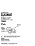
Owner's Manual
ICRRFTSMRNel
21.0 HP
ELECTRIC START
42" MOWER
AUTOMATIC
LAWN TRACTOR
Model No.
917.271840
•
•
•
•
Safety
Assembly
Operation
Maintenance
• Repair Parts
Thls product has a low emlsslon englne which operates
differently from prevlously bullt englnes. Before you start the englne, read and understand thls Owner's Manual.
CAUTION:
For answers to your questions
Read and follow all Safety
Rules and Instructions before
about this product, Call:
operating this equipment.
Sears Craftsman Help Line
5 am - 5 pro, Mon - Set
1-800-659-5917
Sears, Roebuck and Co., Hoffman Estates, II 60179
Visit our Craftsman website:www.sears.com/craftsman
Maintenance .......................................
19
Warranty ...............................................
2
Service and Adjustments .................... 23
SafetyRoles .........................................
3
Product Specifications
..........................
6
Storage ...............................................
29
Troubleshooting ................................. 30
Assembly ..............................................
8
Operation............................................
12
Repair Parts ........................................
34
Maintenance Schedule ......................
19
Parts Ordering ..................... Back Cover
LIMITED TWO YEAR WARRANTY ON CRAFTSMAN RIDING EQUIPMENT PARTS
For two (2) years from the date of pumhase, if this CraftsmanRidingEquipmentis
maintained,lubricatedand tuned up accordingto the instructionsin the owner's
manual, Sears will repair or replace, free of charge, any parts found to be defective in
materialor workmanship.Warranty service is availablefree of charge by takingyour
Craftsmanridingequipmentto your nearest Sears Service Center. In-home warranty
service is availablebut a trip charge will apply.This warrantyapplies onlywhile this
productis in the United States.
This Warranty does not cover:
• Expendable items which become worn during normal use, such as blades, spark
plugs, air cleaners, hers and oil fiRers.
• Tire replacement or repair caused by punctures from outside objects, such as nails,
thorns, stumps, or glass.
• Repairs necessary because of operator abuse, including but not limited to, damage
caused by towing objects beyond the capability of the dding equipment, impacting
objects that bend the frame or crankshaft, or over speeding the engine.
• Repairs necessary because of operator negligence, including but not limited to,
electrical and mechanical damage caused by improper storage, failure to use the
proper grade and amount of engine oil, failure to keep the deck clear of flammable
debris, or the failure to maintain the equipment according to the instructions
contained in the owner's manual.
• Engine (fuel system) cleaning or repairs caused by fuel determined to be contaminated or oxidized (stale). In general, fuel should be used within thirty (30) days of its
purchase date.
• Riding equipment used for commercial or rental purposes.
LIMITED 90 DAY WARRANTY ON BATTERY
For ninety (90) days from date of pumhase, ff any battery included with this riding
equipment proves defective in material or workmanship and our testing determines
the battery will not hold a charge, Sears will replace the battery at no charge. Warranty service is available free of charge by taking your Craftsman riding equipment to
your nearest Sears Service Center. tn-home warranty service is available but a trip
charge will apply. This warranty applies only while this product is in the United States.
TO LOCATE THE NEAREST SEARS SERVICE CENTER OR TO SCHEDULE INHOME WARRANTY SERVICE, SIMPLY CONTACT SEARS AT 1-800-4-MY-HOME
This Warranty gives you specific legal rights, and you may also have other rights
which may vary from state to state.
Sears, Roebuck and Co., D/817 WA, Hoffman Estates, IL 60179
2
IMPORTANT: This cutting machine is capable of amputating hands and feet and
throwing objects. Failure to observe the following safety instructions could result in
serious injury or death.
I. GENERAL OPERATION
I|. SLOPE OPERATION
• Read, understand, and follow all
instructions in the manual and on the
machine before starting.
• Only allow responsible adults, who are
familiar with the instructions, to operate
the machine.
• Clear the area of objects such as
recks, toys, wire, etc., which could be
picked up and thrown by the blade.
• Be sure the area is clear of other
people before mowing. Stop machine
if anyone enters the area.
• Never carry passengers.
• Do not mow in reverse unless absolutely necessary. Always look down
and behind before and while backing.
• Be aware of the mower discharge
direction and do not point it at anyone.
Do not operate the mower without
either the entire grass catcher or the
guard in place.
• Slow down before turning.
• Never leave a running machine
unattended. Always turn off blades, set
parking brake, stop engine, and
remove keys before dismounting.
• Turn off blades when not mowing.
• Stop engine before removing grass
catcher or unclogging chute.
• Mow only in daylight or good artificial
light.
• Do not operate the machine while
under the influence of alcohol or drugs.
• Watch for traffic when operating near or
crossing roadways.
• Use extra care when loading or
unloading the machine into a trailer or
truck.
• Data indicates that operators, age 60
years and above, are involved in a
large percentage of dding mowerrelated injuries. These operators
should evaluate their ability to operate
the riding mower safely enough to
protect themselves and others from
serious injury.
Slopes are a major factor related to loss-ofcontrol and tipover accidents, which can
result in severe injury or death. All slopes
require extra caution. If you cannot back up
the slope or if you feel uneasy on it, do not
mow it.
DO:
• Mow up and down slopes, not across.
• Remove obstacles such as rocks, tree
limbs, etc.
• Watch for holes, ruts, or bumps.
Uneven terrain could overturn the
machine. Tall grass can hide obstacles.
• Use slow speed. Choose a low gear
so that you will not have to stop or shift
while on the slope.
• Follow the manufacturer's recommendations for wheel weights or counterweights to improve stability.
• Use extra care with grass catchers or
other attachments. These can change
the stability of the machine.
• Keep all movement on the slopes slow
and gradual. Do not make sudden
changes in speed or direction.
• Avoid starting or stopping on a slope. If
tires lose traction, disengage the
blades and proceed slowly straight
down the slope.
DO NOT:
• Do not turn on slopes unless necessary, and then, turn slowly and gradually downhill, if possible.
• Do not mow near drop-offs, ditches, or
embankments. The mower could
suddenly turn over if a wheel is over
the edge of a cliff or ditch, or if an edge
caves in,
• Do not mow on wet grass. Reduced
traction could cause sliding.
• Do not try to stabilize the machine by
putting your foot on the ground.
• Do not use grass catcher on steep
slopes.
3
III. CHILDREN
• Never run a machine inside a closed
area.
• Keep nuts and bolts, especially blade
attachment bolts, tight and keep
equipment in good condition.
• Never tamper with safety devices.
Check their proper operation regularly.
• Keep machine free of grass, leaves, or
other debds build-up. Clean oil or fuel
spillage. Allow machine to cool before
stodng.
• Stop and inspect the equipment if you
stdke an object. Repair, if necessary,
before restarting.
• Never make adjustments or repairs
with the engine running.
• Grass catcher components are subject
to wear, damage, and detedoration,
which could expose moving parts or
allow objects to be thrown. Frequently
check components and replace with
manufacturer's recommended parts,
when necessary.
• Mower blades are sharp and can cut.
Wrap the blade(s) or wear gloves, and
use extra caution when servicing them.
• Check brake operation frequently.
Adjust and service as required.
Tragic accidents can occur if the operator
is not alert to the presence of children.
Children are often attracted to the
machine and the mowing activity. Never
assume that children will remain where
you last saw them.
• Keep children out of the mowing area
and under the watchful care of another
responsible adult.
• Be alert and turn machine off if children
enter the area.
• Before and when backing, look behind
and down for small children.
• Never carry children. They may fall off
and be seriously injured or interfere
with safe machine operation.
• Never allow children to operate the
machine.
• Use extra care when approaching blind
comers, shrubs, trees, or other objects
that may obscure vision.
IV. SERVICE
• Use extra care in handling gasoline
and other fuels. They are flammable
and vapors are explosive.
-Use only an approved container.
-Never remove gas cap or add fuel
with the engine running. Allow
engine to cool before refueling. Do
not smoke.
-Never refuel the machine indoors.
- Never store the machine or fuel
container inside where there is an
open flame, such as a water heater.
• Be sure the area is clear of other
people before mowing. Stop machine if
anyone enters the area.
• Never carry passengers or children
even with the blades off.
• Do not mow in reverse unless absolutely necessary. Always look down
and behind before and while backing.
• Never carry children. They may fall off
and be seriously injured or interfere
with safe machine operation.
• Keep children out of the mowing area
and under the watchful care of another
responsible adult.
• Be alert and turn machine off if children
enter the area.
• Before and when backing, look behind
and down for small children.
• Mow up and down slopes (15 ° Max),
not across,
• Remove obstacles such as rocks, tree
limbs, etc.
• Watch for holes, ruts, or bumps.
Uneven terrain could overturn the
machine. Tall grass can hide obstacles.
4
• Use slow speed. Choose a low gear so
that you will not have to stop or shift
while on the slope.
• Avoid starting or stopping on a slope. If
tires lose traction, disengage the
blades and proceed slowly straight
down the slope.
• If machine stops while going uphill,
disengage blades, shift into reverse
and back down slowly.
• Do not turn on slopes unless necessary, and then, turn slowly and gradually downhill, if possible.
,_ CAUTION: Tow only the attachments
that are recommended by and comply
with specifications of the manufacturer of
your tractor. Use common sense when
towing. Operate only at the lowest
possible speed when on a slope. Too
heavy of a load, while on a slope, is
dangerous. Tires can lose traction with
the ground and cause you to lose control
of your tractor.
_bLook for this symbol to point out
important safety precautions. It means
CAUTION!!! BECOMEALERT!!! YOUR
SAFETY IS INVOLVED.
,_WARNING:
Engine exhaust, some of
its constituents, and certain vehicle
components contain or emit chemicals
known to the State of California to cause
cancer and birth defects or other reproductive harm.
_
CAUTION: In order to prevent
accidental starting when setting up,
transporting, adjusting or making repairs,
always disconnect spark plug wire and
place wire where it cannot contact spark
plug.
_kWARNING:
Battery posts, terminals
and related accessories contain lead and
lead compounds, chemicals known to the
State of California to cause cancer and
birth defects or other reproductive harm.
Wash hands after handling.
_lj CAUTION: Do not coast down a hill
in neutral, you may lose control of the
tractor.
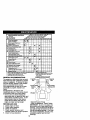
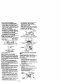
PRODUCT
SPECIFICATIONS
GASOLINE 3.5GALLONS
CAPACITY UNLEADED
ANDTYPE: REGULAR
OILTYPE
SAE30
API-SF-SJ): (ABOVE
32°F)
SAE5W-30
(BELOW
32°F)
OILCAPACITY:
3.0PINTS
SPARK
PLUG: CHAMPION
3AP: .030")
VALVE
ADJUSTMENT
RJt9LM OR J19LM
INTAKE:
.004"-.006"
EXHAUST: .007"-.009"
GROUND
SPEED (MPH):
TIRE
PRESSURE:
FORWARD:
REVERSE:
FRONT:
REAR:
CHARGING
SYSTEM:
3 AMPS BA'I-rERY
5 AMPS HEADLIGHTS
BATTERY:
AMP/HR:
30
MIN. CCA: 240
CASE SIZE:U1R
BLADE BOLT
TORQUE:
27-35 FT. LBS
clans and the proper tools to service or
repair this tractor.
Please read and retain this manual. The
instructions will enable you to assemble
and maintain your tractor properly.
Always observe the =SAFETY RULES".
REPAIR AGREEMENT
A Repair Agreement is availableon this
product, Contactyour nearestSears
store for details.
CUSTOMER
RESPONSIBILITIES
• Read and observe the safety rules.
• Follow a regular schedule in maintaining, caring for and using your tractor.
• Follow the instructions under "Maintenance" and _Storage" sections of this
owner's manual.
5.5
2.4
14 PSI
10 PSI
,_WARNING:
This tractor is equipped
with an internal combustion engine and
should not be used on or near any
unimproved forest-covered, brushcovered or grass-covered land unless the
engine's exhaust system is equipped with
a spark arrester meeting applicable local
or state laws (if any). If a spark arrester is
used, it should be maintained in effective
working order by the operator.
In the state of California the above is
required by law (Section 4442 of the
California Public Resources Code).
Other states may have similar laws.
Federal laws apply on federal lands. A
spark arrester for the muffler is available
through your nearest Sears service
center (See REPAIR PARTS section of
this manual).
CONGRATULATIONS
on your purchase
of a new tractor. It has been designed,
engineered and manufactured to give
you the best possible dependability and
performance.
Should you experience any problem you
cannot easily remedy, please contact a
Sears or other qualified service center.
We have competent, well-trained technio
6
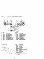
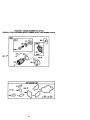
_e
Steering
Wheel
(.)
II
=_
Steering
II
eervi;g
_
Wheel Adapter
__(1)Locknut
_
Steering
I I _-xtension
I°1 Shaft
/
-
/
_
/
_
"__
_,
/
(1) Hex Bolt
Wheel Insed
3/8-16 x 1
(1) Hex Bolt
/
'_11_1__(1
Steering
5/16-18 x 1-1/4
) _rge
Flat
Washer
_
....................
(1) Washer
17/32 x 1-3/16 x 12 Gauge
_(1)
Knob
For Future Use
Keys
Video
(2) Keys
7
Cassette
Slope
Sheet
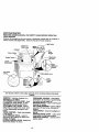
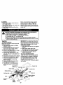
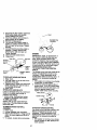
Yournew tractorhas been assembledat the factory with exceptionof those parts left
unassembledfor shippingpurposes. To ensure safe and properoperationof your
tractorall parts and hardwareyou assemblemustbe tightenedsecurely. Use the
correcttoolsas necessaryto insurepropertightness.
TOOLS REQUIRED FOR ASSEMBLY
A socketwrenchsat will make assembly
easier. Standard wrenchsizes you need
are listedbelow.
(1) 9/16" wrench
(1) Pliers
(2) 1/2"wrench
(1) Utilityknife
(1) Tire pressure
gauge
When rightor left hand is mentionedin
this manual, it means when you are in the
operatingposition(seated behindthe
steering wheel).
TO REMOVE TRACTOR FROM
CARTON
UNPACK CARTON
1. Remove all accessibleloose parts
and partscartons from carton.
2. Cut, from top to bottom,along lines on
all four cornersof carton, and lay
panelsflat.
3. Check for any additionalloose parts
or cartonsand remove.
7. Snap steering wheel insert into center
of steering wheel.
8. Remove protective materials from
tractor hood and gdll.
IMPORTANT: Check for and remove any
staples in skid that may puncture tires
where tractor is to roll off skid.
,_F
Wheel Insert
Steedng
Bolt
'_x
_k
,,-_ ....
)
Washer
Large Flat
Washer
Steedngwheel
F
_
_
_eering
Boot
,.epter
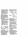
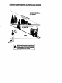
BEFORE REMOVINGTRACTOR
FROM SKID
ATTACH STEERING WHEEL
Lower
Steering _
Shaft
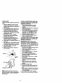
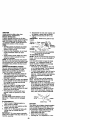
ASSEMBLE EXTENSION SHAFT AND
BOOT
1. Slide extension shaft onto lower
steering shaft. Align mounting holes
in extension and lower shafts and
install 5/16 hex bolt and Iocknut.
Tighten securely.
2. Place tabs of steedng boot over tab
slots in dash and push down to
secure.
INSTALL STEERING WHEEL
3. Position front wheels of the tractor so
they are pointing straight forward.
4. Remove steering wheel adapter from
steering wheel and slide adapter onto
steering shaft extension.
5. Position steering wheel so cross bars
are horizontal (left to right) and slide
inside boot and onto adapter.
6. Assemble large flat washer. 3/8 lock
washer. 3/8 hex bolt and tighten
securely.
/'_"
'"
_!
_
_
_
' I"
ab
, Sots
HOWTO SET UPYOURTRACTOR
CHECK BA'I-rE RY
I. Lift hood to raised position.
NOTE: If this battery is put into service
after month and year indicated on label
(label located between terminals) charge
battery for minimum of one hour at 6-10
amps. (See "BATTERY _ in Maintenance
section of this manual for charging
instructions}.
8
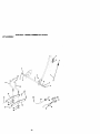
INSTALL SEAT
Adjust seat before tightening adjustment
knob.
I. Remove adjustment knob and flat
washer securing seat to cardboard
packing and set aside for assembly of
seat to tractor.
2. Pivot seat upward and remove from
the cardboard packing, Remove the
cardboard packing and discard.
3. Place seat on seat pan so head of
shoulder bolt is positioned over large
slotted hole in pan.
4. Push down on seat to engage
shoulder bolt in slot and pull seat
towards rear of tractor.
5. Pivot seat and pan forward and
assemble adjustment knob and flat
washer loosely. Do not tighten.
6. Lower seat into operating position and
sit in seat.
7. Slide seat until a comfortable position
is reached which allows you to press
clutch/brake pedal all the way down.
8. Get off seat without moving its
adjusted position.
8. Raise seat and tighten adjustment
knob securely.
Seat
Flat Wa%_
_.
_\\\_,_ \__ I\1
Adju = nt
NOTE: You may now roll or drive your
tractor off the skid. Follow the appropriate
instruction below to remove the tractor
from the skid.
TO ROLLTRACTOR
OFF SKID (See
Operation secUon for location and
funcUon of controls)
1. Press lift lever plunger and raise
attachment lift lever to its highest
position.
2. Release parking brake by depressing
clutch/brake pedal.
3. Place freewheel control in freewheeling position to disengage transmiss=on (See "TO TRANSPORT" in the
Operation section of this manual).
4. Roll tractor forward off skid.
5. Remove banding holding deflector
shield up against tractor.
TO DRIVETRACTOR
OFF SKID (See
OperaUon section for location and
function of controls)
WARNING: Before starting, read
understand and follow all ins'tructons in
the Operation section of this manual, Be
sure tractor is in a well-ventilated area. Be
sure the area in front of tractor is clear of
other people and objects.
1. Be sure all the above assembly steps
have been completed.
2. Check engine oil level and fill fuel
tank with gasoline.
3. Place freewheel control in =transmission engaged" position.
4. Sit on seat in operating position,
depress clutch/brake pedal and set
the parking brake.
5. Place motion control lever in neutral
(N) position.
6. Press lift lever plunger and raise
attachment lift lever to its highest
position.
7. Start the engine. After engine has
started, move throttle control to idle
position.
8. Release parking brake.
9. Slowly move the motion control lever
forward and slowly drive tractor off
skid.
10. Apply brake to stop tractor, set parking
brake and place motion control lever
in neutral position.
11 .Turn ignition key to "OFF" position.
Continue with the instructions that follow.
CHECKTIRE
PRESSURE
The tires on your tractor were overinflated
at the factory for shipping purposes.
Correct tire pressure is important for best
cutting performance.
• Reduce tire pressure to PSI shown in
"PRODUCT SPECIFICATIONS" section
of this manual.
CHECK DECK LEVELNESS
For bestcuttingnesults,mower housing
shouldbe properlyleveled. See "TO
LEVEL MOWER HOUSING" in the
Serviceand Adjustmentssectionof this
manual.
CHECK FOR PROPER POSITION OF
ALL BELTS
See the figuresthat are shownfor
replacingmotionand mower blade drive
beltsin the Service and Adjustments
sectionof thismanual. Verify thatthe
belts are routedcorrectly.
CHECK BRAKE SYSTEM
Afteryou learn how to operateyour
tractor,checkto see thatthe brake is
preperlyadjusted. See "TO ADJUST
BRAKE"in the Service and Adjustments
sectionof this manual.
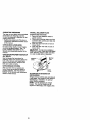
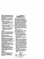
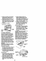
INSTALL
MULCHER
PLATE
(If previously removed)
I.
Raise and hold deflector shield in
upright position.
2. Place front of musher plate over front
of mower deck opening and slide into
place, as shown.
3. Hook front latch into hole on front of
mower deck.
4. Hook rear latch into hole on back of
mower deck.
_CAUTION:
Do not remove deflector
shield from mower. Raise and hold shield
when attaching mulcher plate and allow
it to rest on plate while in operation.
Mulcher
Shield
Latch
Hooks
TO CONVERT TO BAGGING OR
DISCHARGING
Simplyremove mulcher plate and store in
a safe place.Yourmoweris now ready for
dischargingor installationof optional
grass catcher accessory.
NOTE: It is not necessaryto change
b_ades.The mulcher bladesare designed for dischargingand baggingalso.
10
CHECKLIST
BEFORE YOU OPERATE AND ENJOY
YOU R NEW TRACTOR, WE WISH TO
ASSURE THAT YOU RECEIVE THE BEST
PERFORMANCE AND SATISFACTION
FROM THIS QUALITY PRODUCT.
PLEASE REVIEWTHE
CHECKLIST:
FOLLOWING
4
All assembly instructions have been
completed.
J No remaining loose parts in carton.
#" Battery is properly prepared and
charged. (Minimum I hour at 6 amps).
4 Seat is adjusted comfortably and
tightened securely.
J" All tires are propedy inflated. (For
shipping purposes, the tires were
ovednflated at the factory).
,/Be sure mower deck is propedy leveled
side-to-side/front-to-rear for best cutting
results. (Tires must be propedy inflated
for leveling).
,/Check mower and drive belts. Be sure
they are routed properly around pulleys
and inside all belt keepers.
J Check wiring. See that all connections
are still secure and wires are properly
clamped.
,/Before driving tractor, be sure freewheel control is in drive position.
WHILE LEARNING HOWTO USE YOUR
TRACTOR, PAY EXTRA ATTENTION TO
THE FOLLOWING IMPORTANT ITEMS:
#' Engine oil is at proper level.
,/Fuel tank is filled with fresh, clean,
regular unleaded gasoline.
,/" Become familiar with all controls - their
location and function. Operate them
before you start the engine.
4 Be sure brake system is in safe
operating condition.
/ It is important to purge the transmission
before operating your tractor for the first
time. Follow proper starting and
transmission purging instructions (See
"TO START ENGINE" and "PURGE
TRANSMISSION" in the Operation
section of this manual).
11
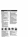
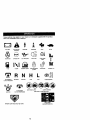
These symbols may appear on your tractor or in literature supplied with the product.
Learn and understand their meaning.
A ÷
8ATTERY
CAUTION OR
WARNING
REVERSE
FORWARD
FAST
SLOW
ENG.NEON
ENG,NEOPP
O,LPRESSURE
L,G.TSON
OV_.P _
FUEL
CHOKE
MOWER HEIGHT
PARKING BRAKE
LOCKED
_r_'l R N H L
ATTACHMENT
CLUTCH ENGAGED
IGNITION
REVERSE
NEUTRAL
ATTACHMENT
CLUTCH DISENGAGED
HIGH
LOW
UNLOCKED
MOWER LIFT
(®)_I
PARKING BRAKE
KEEP AREA CLEAR
SLOPE HAZARDS
(SEE SAFETY RULES SECTION)
FREE WHEEL
(Automatic ModeLsonly)
DANGER, KEEP HANDS AND FEET AWAY
12
KNOWYOURTRACTOR
READ THIS OWNER'S MANUAL AND SAFETY RULES BEFORE OPERATING
YOUR TRACTOR
Compare the illustrationswith yourtractorto familiadzeyourselfwith the locationsof
variouscontrolsand adjustments. Save this manualfor future reference.
Attachment
Clutch Lever
Igni_on
Switch
Ammeter
Lever
Plunger
Choke Control
Throttle
Lift Lever
Clutch/
BrakePedal
Height
Adjustment
Indicator
Free Wheel
Control
Brake Lever
Motion
Lever
Our tractorsconformto the safety standardsof the AmedcanNationalStandards
Institute.
AMMETER - Indicatescharging(+) or
discharging(-) of battery.
ATTACHMENT CLUTCH LEVER - Used
to engagethe mower blades, or other
attachmentsmountedto yourtractor.
ATrACHMENT LIFT LEVER - Used to
raise, lower,and adjustthe mowerdeck
or otherattachmentsmountedto your
tractor.
CHOKE CONTROL - Used when starting
a cold engine.
CLUTCH/BRAKE PEDAL - Used for
declutching and brakingthe tractorand
startingthe engine.
MOTION CONTROL LEVER - Selectsthe
speed and directionof tractor.
FREEWHEEL CONTROL - Disengages
transmission for pushing or slowly towing
the tractor with the engine off.
IGNITION SWITCH - Used for starting and
stopping the engine.
LIFT LEVER PLUNGER - Used to release
attachment lift lever when changing its
position.
LIGHT SWITCH - Turns the headlights on
and off.
PARKING BRAKE LEVER - Locks clutch/
brake pedal into the brake position.
THRO'I-rLE CONTROL - Used to control
engine speed.
13
The operation of any tractor can result in foreign objects thrown into the
eyes, which can result in severe eye damage. Always wear safety
glasses or eye shields while operating your tractor or performing any
adjustments or repairs. We recommend a wide vision safety mask over
spectacles or standard safety glasses.
HOWTO USEYOURTRACTOR
• Never use choke to stop engine.
IMPORTANT: Leaving the ignition switch
in any position other than "OFF" will
cause the battery to be discharged,
(dead).
NOTE: Under certain conditions when
tractor is s_nding idle with the engine
running, hot engine exhaust gases may
cause "browning" of grass. To eliminate
this possibility, always stop engine when
stopping tractor on grass areas.
A_ilLCAUTION: Always stop tractor
completely, as described above, before
leaving the operator's position; to empty
grass catcher, etc.
TO USE THROTTLE CONTROL
TO SET PARKING BRAKE
Your tractor is equipped with an operator
presence sensing switch. When engine
is running, any attempt by the operator to
leave the seat without first setting the
parking brake will shut off the engine.
1. Depress clutch/brake pedal into full
"BRAKE" position and hold.
2. Place parking brake lever in =ENGAGED" position and release
pressure from clutch/brake pedal.
Pedal should remain in =BRAKE"
position. Make sure parking brake will
hold tractor secure.
AttachmentClutch Lever
Choke
Control
Always operate engine at full throttle.
• Operating engine at less than full
throttle reduces the battery charging
rate.
• Full throttle offers the best bagging and
mower performance.
TO USE CHOKE CONTROL
. Ignition Key
Throttle
Control
Parking Brake
"Engaged"
Position
Clutch/
Brake
"Disengaged"
Position
Use choke control whenever you are
starting a cold engine. Do not use to start
a warm engine.
• To engage choke control, pull knob out.
Slowly push knob in to disengage.
TO MOVE FORWARD AND BACKWARD
The direction and speed of movement is
controlled by the motion control lever.
1. Start tractor with motion control lever in
neutral (N) position.
2. Release parking brake and clutch/
brake pedal.
3. Slowly move motion control lever to
desired position.
TO ADJUST MOWER CUTTING HEIGHT
Motion Control
Lever
Position
STOPPING
MOWER BLADES • To stop mower blades,move attachment clutch lever to "DISENGAGED"
position.
GROUND DRIVE • To stop ground drive, depress clutch/
brake pedal into full "BRAKE" position.
• Move motion control lever to neutral (N)
position.
IMPORTANT: The motion control lever
does not return to neutral (N) position
when the clutch/brake pedal is depressed.
ENGINE -
The position of the attachment lift lever
determines the cutting height.
• Grasp lift lever.
• Press plunger with thumb and move
lever to desired position.
The cutting height range is approximately 1-1/2 to 4". The heights are
measured from the ground to the blade
tip with the engine not running.
These heights are approximate and may
vary depending upon soil conditions,
height of grass and types of grass being
mowed.
• Move throttle control to slow position.
NOTE: Failure to move throttle control to
slow position and allowing engine to idle
before stopping may cause engine to
"backfire".
• Turn ignition key to "OFF" position and
remove key. Always remove key when
leaving tractor to prevent unauthorized
USe.
14
• Theaverage
lawnshouldbecutto
approximately
2-1/2inchesduringthe
coolseasonandtoover3 inches
duringhotmonths.Forhealthier
and
betterlooking
lawns,mowoftenand
aftermoderate
growth.
CAUTION: Do not operate the mower
without either the entire grass catcher, on
mowers so equipped, or the deflector
shield in place.
Attachment Clutch
Lever "Engaged"
Position
• For best cutting performance, grass
over 6 inches in height should be
mowed twice. Make the first cut
relatively high; the second to desired
height.
Low
PosRion
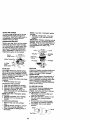
TO ADJUST GAUGE WHEELS
Gauge wheels are properly adjusted
when they are slightly off the ground
when mower is at the desired cutting
height in operating position. Gauge
wheels then keep the deck in proper
position to help prevent scalping in most
terrain conditions.
NOTE: Adjust gauge wheels with tractor
on a flat level surface.
1. Adjust mower to desired cutting height
(See 'q'O ADJUST MOWER CUTTING
HEIGHT" in the Operation section of
this manual).
2. With mower in desired height of cut
position, gauge wheels should be
assembled so they are slightly off the
ground. Install gauge wheel in
appropdata hole with shoulder bolt, 3/
8 washer, and 3/8-16 Iocknut and
tighten securely,
3. Repeat for opposite side installing
gauge wheel in same adjustment
hole.
3/8-16
Locknut\ .
Gauge
Wheel
Mounting
Bracket
3/8 Washer
Gauge Wheel
Attachemnt Lift
Lever High
"Disengaged"
Pos_ee
Shield
TO OPERATE ON HILLS
_CAUTION:
DO not drive up or down
hills with slopes greater than 15° and do
not drive across any slope.
• Choose the slowest speed before
starting up or down hills.
• Avoid stopping or changing speed on
hills.
• If slowing is necessary, move throttle
control lever to slower position.
• If stopping is absolutely necessary,
push clutch/breke pedal quickly to
brake position and engage parking
brake.
• Move motion control lever to neutral (N)
position.
IMPORTANT: The motion control lever
does not return to neutral (N) position
when the clutch/brake pedal is depressed.
• To restart movement, slowly release
parking brake and clutch/brake pedal.
• Slowly move motion control lever to
slowest setting.
• Make all turns slowly.
-_-_
Shoulder
TO TRANSPORT
TO OPERATE MOWER
Your tractor is equipped with an operator
presence sensing switch. Any attempt by
the operator to leave the seat with the
engine running and the attachment clutch
engaged will shut off the engine.
1. Select desired height of cut.
2. Start mower blades by engaging
attachment clutch control.
TO STOP MOWER BLADES disengage attachment clutch control.
When pushing or towing your tractor, be
sure to disengage transmission by
placing freewheel control in freewheeling
position. Free wheel control is located at
the rear drawbar of tractor.
1. Raise attachment lift to highest
position with attachment lift control.
2. Pull freewheel control out and down
into the slot and release so it is held in
the disengaged position.
15
• Do not push or tow tractor at more than
two (2) MPH.
• To reengage transmission, reverse
above procedure.
NOTE: To protect hood from damage
when transporting your tractor on a truck
or a trailer, be sure hood is dosed and
secured to tractor. Use an appropriate
means of tying hood to tractor (rope, cord,
etc.).
TOWING CARTS AND OTHER
A'I-FACH MENTS
Tow only the attachments that are
recommended by and comply with
specifications of the manufacturer of your
tractor. Use common sense when towing.
Too heavy of a load, while on a slope, is
dangerous. Tires can lose traction with
the ground and cause you to lose control
of your tractor.
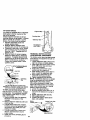
BEFORE STARTINGTHE
ENGINE
CHECK ENGINE OIL LEVEL
The engine in your tractor has been
shipped, from the factory, already filled
with summer weight oil,
1. Check engine oil with tractor on level
ground.
2. Remove oil fill cap/dipstick and wipe
clean, reinsert the dipstick and screw
cap tight, wait for a few seconds,
remove and read oil level. If necessary, add oil until =FULL" mark on
dipstick is reached. Do not overfill.
• For cold weather operation you should
change oil for easier starting(See "OIL
VISCOSITY CHART" in theMaintenance section of this manual).
• To change engine oil, see the Maintenance section in this manual.
ADD GASOLINE
• Fill fuel tank. Use fresh, clean, regular
unleaded gasoline with a minimum of
87 octane. (Use of leaded gasoline
will increase carbon and lead oxide
deposits and reduce valve life). Do not
mix oil with gasoline. Purchase fuel in
quantities that can be used within 30
days to assure fuel freshness.
IMPORTANT: When operating in
temperatures below 32°F(0°C), use fresh,
clean winter grade gasoline to help
insure good cold weather starting.
_WARNING:
Experience indicates that
alcohol blended fuels (called gasohol or
using ethanol or methanol) can attract
moisture which leads to separation and
formation of acids during storage. Acidic
gas can damage the fuel system of an
engine while in storage. To avoid engine
problems, the fuel system should be
emptied before storage of 30 days or
longer. Drain the gas tank, start the
engine and let it run until the fuel lines
and carburetor are empty. Use fresh fuel
next season. See Storage Instructions for
additional information. Never use engine
or carburetor cleaner products in the fuel
tank or permanent damage may occur.
_IeCAUTION: Fill.to bottom of gas.tank
r neck. uo not overfill. Wipe on any
spilled oil or fuel. Do not store, spill or
use gasoline near an open flame.
TO START ENGINE
When startingthe engine for the firsttime or if
the engine has run out of fuel, if willtake extra
crankir_ time to move fuelfrom the tank to
the engine,
1. Be sure freewheel control is in the
transmission engaged position.
2. Sit on seat in operating position,
depress clutch/brake pedal and set
parking brake.
3. Place motion control lever in neutral
(N) position.
4, Move attachment clutch to "DISENGAGED" position.
5. Move throttle control to fast position
6. Pull choke control out for a cold
engine start attempt. For a warm
engine start attempt the choke control
may not be needed,
NOTE: Beforestarling, read the warm and
cold starting proceduresbelow.
7. Insert key into ignition and turn key
clockwise to "START" position and
release key as soon as engine starts.
Do not run starter continuously for
more than fifteen seconds per minute.
If the engine does not start after
several attempts, push choke control
in, wait a few minutes and try again. If
engine still does not start, pull the
choke control out and retry.
WARM WEATHER STARTING (50° F and
above)
8. When engine starts, slowly push
choke control in until the engine
begins to run smoothly, If the engine
starts to run roughly, pull the choke
16
control out slightly for a few seconds
and then continue to push the control
in slowly.
• The attachments and ground drive can
now be used. If the engine does net accept
the load, restartthe engine and allow it to
warm up for one minute usingthe choke
as described above.
COLD WEATHER STARTING (50 ° F and
below)
8. When engine starts, slowly push
choke control in until the engine
begins to run smoothly. Continue to
push the choke control in small steps
allowing the engine to accept small
changes in speed and load, until the
choke control is fully in. If the engine
starts to run roughly, pull the choke
control out slightly for a few seconds
and then continue to push the control
in slowly. This may require an engine
warm-up period from several seconds
to several minutes, depending on the
temperature.
AUTOMATIC TRANSMISSION WARM UP
Before driving the unit in cold weather,
the transmission should be warmed up as
follows:
1. Be sure the tractor is on _evel ground.
2. Place the motion control lever in
neutral. Release the parking brake
and let the clutch/brake slowly return
to operating position,
3. Allow one minute for transmission to
warm up. This can be done during the
engine warm up pedod.
• The attachments can be used during
the enQine warm-up period after the
transmission has been warmed up and
may require the choke control be
pulled out slightly.
NOTE: If at a high altitude (above 3000
feet) or in cold temperatures (below 32 F)
the carburetor fuel mixture may need to
be adjusted for best engine performance.
See "TO ADJUST CARBURETOR" in the
Service and Adjustments section of this
manual.
PURGETRANSMISSION
_I_CAUTION: Never engage or disengage freewheel lever while the engine is
running.
To ensure proper operation and performance, it is recommended that the
transmission be purged before operating
tractor for the first time.
This procedure will remove any trapped air
inside the transmission which reay have
developed during shipping of your tractor.
IMPORTANT: Should your transmission
require removal for service or replacement,
it should be purged after reinstallation
before operating the tractor.
1. Place tractor safely on level surface
with engine off and parking brake set.
2. Disengage transmission by placing
freewheel control in freewheeling
position (See "TO TRANSPORT" in
this section of manual).
3. Sitting in the tractor seat, start engine.
After the engine is running, move
throttle control to stow position. With
motion control lever in neutral (N)
position, slowly disengage clutch/
brake pedal.
4. Move motion control lever to full
forward position and hold for five (5)
seconds. Move lever to full reverse
position and hold for five (5) seconds.
Repeat this procedure three (3) times.
NOTE: During this procedure there will be
no movement of drive wheels. The air is
being removed from hydraulic drive
system.
5. Move motion control lever to neutral
(N) position. Shut- off engine and set
parking brake.
6. Engage transmission by placing
freewheel control in driving position
(See "TO TRANSPORT" in this section
of manual).
7. Sitting in the tractor seat, start engine.
After the engine is running, move
throttle control to half (1/2) speed. With
motion control lever in neutral (N)
position, slowly disengage clutch/
brake pedal.
8. Slowly move motion control lever
forward, after the tractor moves
approximately five (5) feet, slowly
move motion control lever to reverse
position, After the tractor moves
approximately five (5) feet retum the
motion control lever to the neutral (N)
position, Repeat this procedure with
the motion control lever three (3)
times.
Your tractor is now purged and now ready
for normal operation.
17
MOWINGTIPS
MULCHING
• Mower should be properly leveled for
best mowing performance. See =TO
LEVEL MOWER HOUSING" in the
Service and Adjustments section of this
manual.
• The left hand side of mower should be
used for trimming.
• Drive so that clippings are discharged
onto the area that has been cut. Have
the cut area to the dght of the tractor.
This will result in a more even distribution of clippings and more uniform
cutting.
• When mowing large areas, start by
turning to the right so that clippings will
discharge away from shrubs, fences,
driveways, etc. After one or two
rounds, mow in the opposite direction
making left hand tums until finished.
• If grass is extremely tall, it should be
mowed twice to reduce load and
possible fire hazard from dried clippings. Make first cut relatively high; the
second to the desired height.
• Do not mow grass when it is wet. Wet
grass will plug mower and leave
undesirable clumps. Allow grass to dry
before mowing.
• Always operate engine at full throttle
when mowing to assure better mowing
performance and proper discharge of
material. Regulate ground speed by
selecting a low enough gear to give the
mower cutting performance as well as
the quality of cut desired.
• When operating attachments, select a
ground speed that will suit the terrain
and give best performance of the
attachment being used.
IMPORTANT: For best performance,
keep mower housing free of built-up
grass and trash. Clean after each use.
• The special mulching blade will recut
the grass clippings many times and
reduce them in size so that as they fall
onto the lawn they will disperse into the
grass and not be noticed. Also, the
mulched grass will biodegrade quickly
to provide nutrients for the lawn.
Always mulch with your highest engine
(blade) speed as this willprov_le the
best recutting action of the blades.
• Avoid cutting your lawn when it is wet.
Wet grass tends to form clumps and
interferes with the mulching action.
The best time to mow your lawn is the
early eftemoon. At this time the grass
has dried and the newly cut area will
not be exposed to the direct sun.
• For best results, adjust the mower
cutting height so that the mower cuts off
only the top one-third of the grass
blades. For extremely heavy mulching,
reduce your width of cut on each pass
and mow slowly.
• Certain types of grass and grass
conditions may require that an area be
mulched a second time to completely
hide the clippings. When doing a
second cut, mow across or perpendicular to the first cut path.
• Change your cutting pattern from week
to week. Mow north to south one week
then change to east to west the next
week. This will help prevent matting
and graining of the lawn.
f
t
4p.
J
18
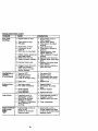
MOWINGTIPS
I - Cha_le mcre oilen v/neff operM_g
tm<_r Iz heavy k)ad or in h_h ar_Dkrnt lempe,_n"_'es
S - If _4d
7 - Tl_,_n
GENERAL
vAIh al_,_abJe s_efil.
f ford _
Id:_,_tball to 36 ft -hi. rt1_11um.
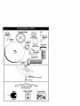
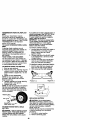
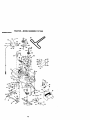
LUBRICATION
"--'-----_
_) Spindle
RECOMMENDATIONS
The warranty on this tractor does not cover
items that have been subjected to operator
abuse or negligence. To receive full value
from the warranty, operator must maintain
tractor as instructed in this manual.
Some adjustments will need to be made
periodically to propedy maintain your
tractor.
All adjustments in the Service and
Adjustments section of this manual should
be checked at least once each season.
• Once a year you should replace the
spark plug, clean or replace air filter, and
check blades and belts for wear. A new
spark plug and clean air filter assure
proper air-fuel mixture and help your
engine run better and last longer.
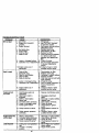
BEFORE EACH USE
CHART
r_-- (_ Spindle
Zor r."l
_)Front Wheel ,..
Bssring
/
Zerk _
_)Engine" o_'
(_)Generel Purpose Grease
_)Refer to Maintenance "Engine" Section
IMPORTANT: Do not oil or grease the
pivot points which have special nylon
bearings. Viscous lubricants will attract
dust and dirt that will shorten the life of
the self-lubricating bearings. If you feel
they must be lubricated, use only a dry,
powdered graphite type lubricant
sparingly.
1.
2.
3.
4.
Check engine oil level.
Check brake operation.
Check tire pressure.
Check operator presence and
interlock systems for proper operation.
5. Check for loose fasteners.
19
_R
Always observe safety rules when
performing any maintenance.
BRAKE OPERATION
If tractor requires more than six (6) feet
stopping distance at high speed in highest
gear, then brake must be adjusted. (See
"TO ADJUST BRAKE in the Service and
Adjustments section of this manual),
TIRES
• Maintain proper air pressure in all tires
(See "PRODUCT SPECIFICATIONS"
section of this manual).
• Keep tires free of gasoline, oil, or insect
contmt chemicals which can harm
rubber.
• Avoid stumps, stones, deep ruts, sharp
objects and other hazards that may
cause tire damage.
NOTE: To seastire punctures and prevent
flat tires due to slow leaks, tire sealant may
be purchesed from your local parts dealer.
Tire sealant also prevents tire dry rot and
corrosion.
OPERATOR PRESENCE SYSTEM
Be sure operator presence and intedock
systems are working properly. If your
tractor does not function as described,
repair the problem immediately.
• The engine should not start unless the
clutch/brake pedal is fully depressed
and attechement clutch control is in the
disengaged position.
• When the engine is running, any attempt
by the operator to leave the seat without
first setting the parking brake shouSd
shut off the engine.
• When the engine is running and the
attachment clutch is engaged, any
attempt by the operator to leave the seat
sho_k:lshut off the engine.
• The attachment clutch should never
operate unless the operator is in the
seat.
BLADE CARE
Far best results mower blades must be
kept sharp. Replace bent or damaged
blades.
BLADE REMOVAL
I. Raise mower to highest position to
a$$owaccess to blades.
2. Remove hex bolt, lock washer and flat
washer securing blade.
3. install new or resharpened blade with
trailing edge up towards deck as
Shown.
IMPORTANT: To ensure proper assembly,
center hole in blade must align with star on
mandrel assembly.
4, Reassemble hex bolt, lock washer and
fiat washer in exact order as shown.
5. Tighten bolt securely (27-35 Ft. Lbs.
torque).
IMPORTANT: Blade bolt is grade 8 heat
treated.
Trailing_
Blade Center.J_
Edge Up ((/_.\
Hole _
_'_
Lock Washer "_'_
=_'_
Assembly
Hex Bolt
"_
_'_'_-\
Star
(Grade)*'_ -" Flat Washer/_
*A Grade 8 heat treatedbolt can be identified
by six lineson the bolt head.
TO SHARPEN BLADE
NOTE: We do not recommend sharpening
blade - but if you do, be sure the blade is
balanced.
Care should be taken to keep the blade
balanced. An unbalanced blade will
cause excessNe vibration and eventual
damage to mower and engine.
• The blade can be sharpened with a file
or on a gdnding wheel. Do not attempt
to sharpen while on the mower.
• To check blade balance, you will need a
5/8" diameter steel bolt, pin, or a cone
balancer. (When using a cone balancer,
follow the instructions supplied with
balancer.)
NOTE: Do not use a nail for balancing
blade. The lobes of the center hole may
appear to be centered, but are not.
• Slide blade on to an unthreaded portion
of the steel bolt or pin and hold the bolt
or pin parallel with the ground. If blade
is balanced, it should remain in a
hodzontal position. If either end of the
bSede moves downward, sharpen the
heavy end until the blade is balanced.
/
5/8" Bolt
or Pin
Center Hole
BATTERY
Your tractor has a batterycharging system
which is sufficient for normal use. However, pedndic charging of the battery with
an automotive charger will extend its life.
• Keep battery and terminals clean.
• Keep battery botts tight.
• Keep small vent holes open.
• Recharge at 6-10 amperes for 1 hour.
2O
NOTE: The ofig'_nalequipment battery on
your tractor is maintenance free, Do not
attempt to open or remove caps or covers.
Adding or checking level of electrolyte is
not necessary.
TO CLEAN BATTERY AND TERMINALS
Corrosion and dirt on the battery and
terminals can cause the battery to "leak"
power.
1. Remove terminal guard.
2. Disconnect BLACK battery cable first
then RED battery cable and remove
batten/from tractor.
3. Rinse the battery with plain water and
dry.
4. Clean terminals and battery cable ends
with wire brush until bright.
5. Coat terminals with grease or petroeum
ally.
6. Reinstall battery (See =REPLACING
BATTERY" in the SERVICE AND
ADJUSTMENTS section of this
manual).
V-BELTS
Check V-belts for deterioration and wear
after 100 hours of operation and replace if
necessary. The belts are not adjustable.
Replacebeits if they begin to slip from
wear.
TRANSAXLE COOLING
The transmission fan and cooling fins
should be kept clean to assure proper
cooling.
Do not attempt to clean fan or transmission
while engine Is running or while the
transmission is hot. To prevent possible
damage to seals, do not use high pressure
water or steam to clean transaxle.
• Inspect cooling fan to be sure fan blades
are intact and clean.
• inspect cooling fins for dirt, grass
clippings and other materials. To prevent
damage to seals, do not use compressed
air or high pressure sprayer to clean
cooling fins.
TRANSAXLE PUMP FLUID
The transaxle was sealed at the factory
and fluid maintenance is not required for
the life of the transaxle. Should the
transaxle ever leak or require servicing,
contact your nearest authorized service
canter/department.
ENGINE
LUBRICATION
Only use high quality detergent oil rated
with API service classification SF-SJ.
Select the oil's SAE viscosity grade
according to your expected operating
temperature.
NOTE: Although multi-viecosity oils
(5W30, 10W30 etc.) improve starting in
cold weather, those multi-viscosity oils will
result in increased oil consumption when
used above 32°F. Check your engine oil
level more frequently to avoid possible
engine damage from running low on oil.
Change the oil after every 25 hours of
operation or at least once a year if the
tractor is not used for 25 hours in one year.
Check the crankcase oil level before
starting the engine and after each eight (8)
hours of operation. Tighten oil fill cap/
dipstick securely each time you check the
oil level.
TO CHANGE ENGINE OIL
Determine temperature range expected
before oilchange. All oil must meet API
service classification SF-SJ.
• Be sure tractor is on level surface.
• Oil will drain more freely when warm.
• Catch oil in a suitable container.
1. Remove oil fill cap/dipstick. Be careful
not to allow dirt to enter the engine
when changing oil.
2. Remove cap from end of drain valve
and install the drain tube onto the
fitting.
3. Unlock drain valve by pushing Inward
slightly and turning countemlockwise.
4. To open, pull out on the drain valve.
5. After oil has drained completely, close
and lock the drain valve by pushing
inward and turning clockwise until the
pin is in the locked position as shown.
6. Remove the drain tube and replace the
cap onto to the end of the drain valve.
7. Refill engine with oil through oil fill
dipstick tube. Pour slowly. Do not
overfill. For approximate capacity see
"PRODUCT SPECIFICATIONS" section
of this manual.
8. Usa gauge on oit fitt cap/dipstick for
checking level. Be sure dipstick cap is
tightened securely for accurate
reading. Keep oil at "FULL" line on
dipstick.
Oil Drain Valve
Closed
and "-----_-_l_
Locked
i:-_ --'_
Position
21
_:,_¥
"°
_OrainTube
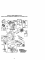
CLEAN AIR SCREEN
Air screen must be kept free of dirt and
chaff to prevent engine damage from
overheating. Clean with a wire brush or
compressed air to remove dirt and
stubborn dried gum fibers.
ENGINE COOLING RNS
Remove any dust, dirt or oil from engine
cooling fins to prevent engine damage
from overheating. Air guide covers must
be removed. Remove side panels and
hood (See "TO REMOVE HOOD AND
GRILL ASSEMBLY" in the Service and
Adjustments section of this manual).
NOTE: If very dirty or damaged, replace
cartridge.
4. Reinstall cartddge plate, wing nuts,
precleaner, cover and secure with
knob(s).
IMPORTANT: Petroleum solvents, such as
kerosene, are not to be used to clean the
cartridge. They may cause deterioration of
the cartridge. Do not oil cartridge. Do not
use pressurized air to clean or dry
cartridge.
Plate
Top Air
Guide Cover-_L__l
Foam PreCleaner
_-
Engine Cooling F
_r Guide
Air Screen
Cartddgs
::_2
Cover
"%_
(Both Sides) @
AIR FILTER
Your engine will not run properly using a
dirty air filter. Clean the foam pre-cleaner
after every 25 hours of operation or every
season. Service paper cartridge every100
hours of operation or every season,
whichever occurs first.
Service air cleaner more often under dusty
conditions.
1. Remove knob(s) and cover.
TO SERVICE PRE-CLEANER
2. Slide foam pre-cleaner off cartddge.
3. Wash it in liquid detergent and water,
4. Squeeze it dry in a clean cloth.
5. Saturate it in engine oil. Wrap it in
clean, absorbent cloth and squeeze to
remove excess oil.
NOTE: If very dirty or damaged, replace
0re-cleaner.
3. Reinstall prs-cleaner over cartridge.
7. Reinstall cover and secure with
knob(s).
TO SERVICE CARTRIDGE
f. Remove wing nuts and cartridge
plate.
-_. Carefully remove cartridge to prevent
debds from entering carburetor.
_. Clean cartridge by tapping gently on
flat surface.
MUFFLER
Inspect and replace corroded muffler and
spark arrester (if equipped) as it could
create a fire hazard and/or damage.
SPARK PLUGS
Replace spark plugs at the beginning of
each mowing season or after every 100
hours of operation, whichever occurs first.
Spark plug type and gap setting are
shown in "PRODUCT SPECIFICATIONS"
section of this manual.
IN-LINE FUEL FILTER
The fuel filter should be replaced once
each season. If fuel filter becomes
clogged, obstructing fuel flow to carburetor, replacement is required.
1. With engine cool, remove fitter and
plug fue! line sections.
2. Place new fuel filter in position in fuel
• line with arrow pointing towards
carburetor.
3, Be sure there are no fuel line leaks
and clamps are properly positioned.
4. Immediately wipe up any spilled
gasoline.
cm
22
CLEANING
• Clean engine, battery, seat, finish, etc.
of all foreign matter.
• Keep finished surfaces and wheels free
of all gasoline, oil, etc.
• Protect painted surfaces with automotive type wax.
A
We do not recommend using a garden
hose to clean your tractor unless the
electrical system, muffler, air filter and
carburetor are covered to keep water out.
Water in engine can result in a shortened
engine life.
CAUTION: BEFORE PERFORMING ANY SERVICE OR ADJUSTMENTS:
I. Depressclutch/brakepedal fullyand set parkingbrake.
2. Place motioncontrollever in neutral (N) position.
3. Place attachmentclutch in "DISENGAGED_ position.
4. Turn ignitionkey "OFF"and remove key.
5. Make sure the bladesand all movingparts have completelystopped.
6. Disconnectspark plug wire from spark plug and place wire where it cannot
come in contactwith plug.
IMPORTANT: If an attachment other than
the mower deck is to be mounted on the
tractor, remove the front links and hook the
clutch spring Into square hole in frame.
TO INSTALL MOWER
TRACTOR
TO REMOVE MOWER
Mower will be easier to remove from the
right side of tractor.
1. Place attachment clutch in =DISENGAGED" position.
2. Move attachment lift lever forward to
lower mower to its lowest position.
3. RoU belt off engine pulley.
4. Remove small retainer spring, and lift
clutch spring off pulley bolt.
5. Remove large retainer spring, slide
collar off and push housing guide out
of bracket.
6. Disconnect anti-swaybar from chassis
bracket by removing retainer spring.
7. Disconnect suspension arms from
roar deck brackets by removing
retainer springs.
8. Disconnect front links from deck by
removing retainer springs.
9. Raise lift lever to raise suspension
arms. Slide mower out from under
tractor.
1. Raise attachment lift lever to its highest
position.
2. Slide mower under tractor with
discharge guard to right side of tractor.
3. Lower lift lever to its lowest position.
4. install mower in reverse order of
removal instructions.
TO LEVEL MOWER HOUSING
Adjust the mower while tractor is parked
on level ground or driveway. Make sure
tires are properly inflated (See "PRODUCT SPECIFICATIONS" section of this
manual). If tires are over or
underinflated, you will not properly adjust
your mower.
Retainer Spdn
Anti-Swa
Springs
(Both Sides)
Guide
Large
Retainer
Spring
Bracket
23
SIDE-TO-SIDE ADJUSTMENT
• Raise mower to its highest position.
• At the midpoint of both sides of mower,
measure height from bottom edge of
mower to ground. Distance "A" on both
sides of mower should be the same or
within 1/4" of each other.
• If adjustment is necessary, make
adiustment on one side of mower only.
• To raise one side of mower, tighten lift
link adjustment nut on that side.
• To lower one side of mower, loosen lift
link adjustment nut on that side.
NOTE:Each full turn of adjustment nut will
change mower height about 1/8".
• Recheck measurements after adjusting.
Bottom edge of
• To raise front of mower, loosen nut =F"
from trunnion on both front links.
Tighten nut "15"on both front links an
equal number of turns.
• When distance "[7' is 1/8" to 1/2" lower
at front than rear, tighten nut "F" against
trunnion on both front links.
• Recheck side-to-side adjustment.
%,
.
oo_
Mandrel
BothFrontLinksShouldbe Equal in Length
Bottomedge of
owo w u°
G=n,
Nut
JT;
Suspension
Front
Lift Link Ad_
FRONT-TO-BACK ADJUSTMENT
IMPORTANT: Deck must be level side-to
side. If the following front-to-back adjustment is necessary, be sure to adiust both
front links equally so mower will stay level
side-to-side.
To obtain the best cutting results, the
mower housing should be adjusted so
that the front is approximately 1/8" to 1/2"
lower than the rear when the mower is in
its highest position.
Check adjustment on right side of tractor.
Measure distance "13"directly in front and
behind the mandrel at bottom edge of
mower housing as shown.
• Before making any necessary adjustments, check that both front links are
equal in length. Both links should be
approximately
10-3/8".
• If links are not equal in length, adjust
one link to same length as other link.
• To lower front of mower loosen nut "E"
on both front links an equal number of
turns.
• When distance "D" is 1/8" to 1/2" lower
at front than rear, tighten nuts =F"
against trunnion on both front links.
TO REPLACE MOWER BLADE DRIVE
BELT
The mower blade drive belt may be
replaced without tools. Park the tractor on
level surface. Engage parking brake.
BELT REMOVAL 1. Remove mower from tractor (See "TO
REMOVE MOWER" in this section of
this manual).
2. Work belt off both mandrel pulleys and
idler pulleys.
3. Pull belt away from mower,
BELT INSTALLATION 4. Install new belt in reverse order of
removal.
5. Make sure belt is in all pulley grooves
and inside all belt guides.
6. Install mower in reverse order of
removal instructions.
Mandrel
Pulley _.
24
Idler Pulleysj.-_
#_
^
_
TO ADJUST BRAKE
Your tractor is equipped with an adjustable
brake system which is mounted on the
side of the transaxle.
If tractor requires more than six (6) feet
stopping distance at high speed in highest
gear on a level dry concrete or paved
surface, then brake must be adjusted.
1. Depress clutch/brake pedal and
engage parking brake.
2. Measure distance between brake
operating arm and nut "A" on brake rod.
3. If distance is other than 1-9/16", loosen
jam nut and tum nut "A"until distance
becomes 1-9/16". Retighten jam nut
against nut "A'.
4. Road test tractor for proper stopping
distance as stated above. Readjust if
necessary. If stopping distance is still
greater than six (6) feet in highest gear,
further maintenance is necessary.
Contact your nearest Sears or other
qualified center.
WITH
PARKING BRAKE
"ENGAGED"
_ Operating
Arm
If further brake
adjustmentis necessary contactyour nearest
authodzed service centar/department
EnginePulley-ClutchingIdler _
_1
StationaryIdler j
TRANSAXLE MOTION CONTROL
LEVER NEUTRAL ADJUSTMENT
The motion control lever has been preset
at the factory and adjustment should not
be necessary.
1. Loosen adjustment bolt in front of the
right rear wheel, and lightly tighten.
2. Start engine and move motion control
lever until tractor does not move
• forward or backward.
3. Hold motion control lever in that
position and turn engine off.
4. While holding motion control lever in
place, loosen the adjustment bolt.
5. Move motion control lever to the
neutral (N) (lock gate) position.
6. Tighten adjustment bolt securely.
NOTE: If additional clearance is needed
to get to adjustment bolt, move mower
deck height to the lowest position.
After above adjustment is made, if the
tractor still creeps forward or backward
while motion control lever is in neutral
position, follow these steps:
1. Loosen the adjustment bolt.
2. Move the motion control lever 1/4 to
1/2 inch in the direction it is trying to
creep.
3. Tighten adjustment bolt securely.
4. Start engine and test.
5. If tractor still creeps, repeat above
steps until saltsfied.
Motion
Neutral Lock Gate
Control
TO REPLACE MOTION DRIVE BELT
Park the tractor on level surface. Engage
parking brake. For assistance, there is a
belt instaltation guide decal on bottom
side of left footrest.
1. Remove mower (See "TO REMOVE
MOWER" in this section of this
manual.)
2. Remove belt from stationary idler and
clutching idler.
3. Pull belt slack toward rear of tractor.
Carefully remove belt upwards from
L
transmission input pulley and over
cooling fan blades.
4. Pull belt toward front of tractor and
remove downward from arou_l
engine pulley.
5. install new belt by reversing above
procedure.
25
";"
Adjustment Bolt
TRANSMISSION
MENT
REMOVAUREPLACE-
Should your transmission require
removal for service or replacement, it
should be purged after reinstallation and
before operating the tractor. See "PURGE
TRANSMISSION" in the Operation
section of this manual.
TO ADJUST STEERING WHEEL ALIGNMENT
If steering wheel crossbars are not
horizontal (left to dght) when wheels are
positioned straight forward, remove
steering wheel and reassemble per
instructions in the Assembly section of
this manual.
FRONT WHEEL TOE-IN/CAMBER
The front wheel toe-in and camber are
not adjustable on your tractor. If damage
has occurred to affect the front wheel toein or camber, contact your nearest Sears
or other qualified service center.
If yourbattery istoo weak to startthe engine, it
shouldbe recharged. (See "BATfERY" in the
MAINTENANCE section of thismanual).
If "jumpercables"are used for emergency
_ting,
fo#ow this procedure:
IMPORTANT: Yourtractoris equipped with a
12 voltnegative grounded system.The other
vehical must also be a 12 volt negative
grounded system. Do notuse yourtractor
battery to startother vehicles.
TO ATTACH JUMPER CABLES 1. Connect each end of the RED cable to
the POSITIVE (+) terminal of each
battery, taking care not to short
against chassis.
2. Connect one end of the BLACK cable
to the NEGATIVE (-) terminal of fully
charged battery.
3. Connect the other end of the BLACK
cable to good CHASSIS GROUND,
away from fuel tank and battery.
TO REMOVE CABLES, REVERSE ORDER 1. BLACK cable first from chassis and
then from the fully charged battery.
2. RED cable last from both batteries.
TO REMOVE WHEEL FOR REPAIRS
1. Block up axle securely.
2. Remove axle cover, retaining ring and
washers to allow wheel removal (rear
wheel contains a square key - Do not
lose).
3. Repair tire and reassemble.
NOTE: On rear wheels only: align
grooves in rear wheel hub and axle.
Insert square key.
4. Replace washers and snap retaining
ring securely in axle groove.
5. Replace axle cover,
NOTE= To seal tire punctures and prevent
flat tires due to slow leaks, tire sealant
may be purchased from your local parts
dealer. Tire sealant also prevents tire dry
,x,e\
_tet_i_idni Rrirn_Si
° n"
"Positive" (+)
flrf
_
REPLACING
D
"Negative" (-)
BATTERY
/&CAUTION:
Do not short battery
terminals by allowing a wrench or any
other object to contact both terminals at
the same time. Before connecting battery,
remove metal bracelets, wristwatch
bands, rings, etc.
Positive terminal must be connected first
to prevent sparking from accidental
grounding.
1. Lift hood to raised position.
2. Remove terminal guard.
Square Key ------.._=_-'
(Rear Wheel Only)
TO START ENGINE WITH A WEAK
BATTERY
_1_CAUTION: Lead-acid batteriesgenerate
e_plosivegases. Keep spanks,flame and
smoking materialsaway from batteries.
Always wear eye protectionwhen around
batteries.
26
3. Disconnect BLACK battery cable then
RED battery cable and carefully
remove battery from tractor.
4. Install new battery with terminals in
same position as old battery.
5. Reinstall terminal guard.
6. First connect RED battery cable to
positive (+) battery terminal with hex
bolt and keps nut as shown. Tighten
securely.
7. Connect BLACK grounding cable to
negative (-) battery terminal with
remaining hex bolt and kepe nut.
Tighten securely
8. Close terminal access doors.
9. Close hood.
Keps Nut\ _
Termina: :
. ...... _
_
Hex Bolt
"_
Door_
_.__
[_1__
Guard
(Red)
Cable
_
Cable
TO REPLACE HEADLIGHT BULB
1. Raise hood.
2. Pull bulb holder out of the hole in the
backside of the gdll.
3. Replace bulb in holder and push bulb
holder securely back into the hole in
the backside of the grill.
4. Close hood.
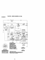
INTERLOCKS AND RELAYS
Loose or damaged wiring may cause your
tractor to run poorly, stop running, or
prevent it from starting.
• Check wiring. See electrical wiring
diagram in the Repair Parts section.
TO REPLACE FUSE
Replace with 20 amp automotive-type
plug-in fuse. The fuse holder is located
behir_:l
the dash.
TO REMOVE HOOD AND GRILL
ASSEMBLY
1. Raise hood.
2. Unsnap headlight wire connector.
3. Stand in front of tractor. Grasp hood at
sides, tilt toward engine and lift off of
tractor.
4. To replace, reverse above procedure.
Hood
Ii I •
\
/
I
HeadlightWire
Connector
,/ ,:_
ENGINE
Maintenance, repair, or replacement of
the emission control devices and systems, which are being done at the
customers expense, may be performed
by any non-road engine repair establishment or individual. Warranty repairs must
be performed by an authorized engine
manufacturers service outlet.
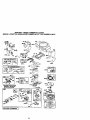
TO ADJUST THROTTLE CONTROL
CABLE
The thrcttle control has been preset at the
factory and adjustment should not be
necessary. Check adjustment as described below before loosening cable. If
adjustment is necessary, proceed as
follows:
1. With engine not running, move throttle
control lever to fast position.
2. Check that swivel is against side of
quarter circle. If it is not, loosen cable
clamp screw and pull cable back until
swivel is against quarter cimle.
Tighten cable clamp screw securely.
Clamp Screw
Quarter Circle
TO ADJUST CHOKE CONTROL
The choke control has been preset at the
factory and adjustment should not be
necessary. Check adjustment as described below before loosening cable. If
adjustment is necessary, proceed as
follows:
1. With engine not running, move choke
control (located on dash panel) to full
choke position.
27
2. Remove air cleaner cover, filter and
cartridge plate to expose carburetor
choke (see =AIR FILTER" in the
Maintenance section of this manual).
3. Choke should be closed. If it is not,
loosen casing clamp screw and move
choke cable until choke is completely
closed. Tighten casing clamp screw
securely.
4 Reassemble air cleaner.
3. While still holding throttle lever
against idle speed screw, turn idle
mixture screw In (clockwise) until
engine begins to die and then turn out
(counterclockwise) until engine runs
rough. Turn screw to a point midway
between those two positions.
4. Continue to hold throttle lever against
idle speed screw and adjust idle
speed screw to obtain 900 to 1200
RPM. Release throttle lever.
Chok
Casing
Clamp
Screw
ACCELERATION TEST 5. Move throttle control lever from slow
to fast position. If engine hesitates or
dies, tum idle mixture screw out
(countemlockwise) 1/8 turn. Repeat
test and continue to adjust, if necessary, until engine accelerates
smoothly.
High speed stop is factory adjusted. Do
not adjust - damage may result.
IMPORTANT: Never tamper with the
engine governor, which is factory set for
proper engine speed. Overspeeding the
engine above the factory high speed
setting can be dangerous. If you think the
engine-governed high speed needs
adjusting, contact your nearest Sears or
other qualified service center, which has
proper equipment and experience to
make any necessary adjustments.
Choke
Lever
TO ADJUST CARBURETOR
The carburetor has been preset at the
factory and adjustment should not be
necessary. However, minor adjustment
may be required to compensate for
differences in fuel, temperature, altitude
or load. If the carburetor does need
adjustment, proceed as follows:
In general, turning the mixture screw in
(clockwise) decreases the supply of fuel
to the engine giving a leaner fueVair
mixture. Turning the mixture screw out
(counterclockwise) increases the supply
of fuel to the engine giving a richer fueV
air mixture.
IMPORTANT: Damage to the needles
and the seats in carburetor may result if
screw is turned in too tight.
PRELIMINARY SETTING -
e Mixture
rew
6
1. Be sure you have a clean air filter, and
the throttle control cable and choke
are adjusted propedy (see above).
2. With engine off turn idle mixture screw
in (clockwise) closing it finger tight
and then turn out (counterclockwise)
1-1/4 to 1-1/2 turns.
Lever
Idle Speed
FINAL SETTING 1. Start engine and allow to warm for five
minutes. Make final adjustments with
engine running and shift/motion
control lever in neutral (N) position.
2. With throttle control lever in slow
position, hold throttle lever against
idle speed screw and adjust idle
speed screw to obtain 1200 to 1400
RPM.
Lever
_
Idle Mixture Screw
28
Immediately prepare your tractor for
storage at the end of the season or if the
tractor will not be used for 30 days or
more.
• 1,CAUTION: Never store the tractor with
gasoline in the tank inside a building
where fumes may reach an open flame or
spark. Allow the engine to cool before
storing in any enclosure.
TRACTOR
Remove mower from tractor for winter
storage. When mower is to be stored for
a period of time, clean it thoroughly,
remove all dirt, grease, leaves, etc. Store
in a clean, dry area.
1. Clean entire tractor (See "CLEANING"
in the Maintenance section of this
manual).
2. Inspect and replace belts, if necessary
(See belt replacement instructions in
the Service and Adjustments section
of this manual).
3. Lubricate as shown in the Maintenance section of this manual.
4. Be sure that all nuts, bolts and screws
are securely fastened. Inspect moving
parts for damage, breakage and wear.
Replace if necessary.
5. Touch up all rusted or chipped paint
surfaces; sand lightly before painting.
BATTERY
Also, experiance indicates that alcohol
blended fuels (called gasohol or using
ethanol or methanol) can attract moisture
which leads to separation and formation
of acids dudng storage. Acidic gas can
damage the fuel system of and engine
while in storage.
1. Drain the fuel tank.
2. Start the engine and let it run until the
fuel lines and carburetor are empty.
• Never use engine or carburetor cleaner
products in the fuel tank or permanent
damage may occur.
• Use fresh fuel next season.
NOTE: Fuel stabilizer is an acceptable
alternative in minimizing the formation of
fuel gum deposits during storage. Add
stabilizer to gasoline in fuel tank or
storage container. Always follow the mix
ratio found on stabilizer container. Run
engine at least 10 minutes after adding
stabilizer to allow the stabilizer to reach
the carburetor. Do not drain the gas tank
and carburetor if using fuel stabilizer.
ENGINE OIL
Drain oil (with engine warm) and replace
with clean engine oil. (See "ENGINE" in
the Maintenance section of this manual).
CYLINDER(S)
1. Remove spark plug(s).
2. Pour one ounce of oil through spark
plug hole(s) into cylinder(s).
3. Tum ignition key to "START" position
for a few seconds to distribute oil.
4. Replace with new spark plug(s).
• Fully charge the battery for storage.
• After a pedod of time in storage, battery
may require recharging.
• To help prevent corrosion and power
leakage during long pedods of storage,
battery cables should be disconnected
and battery cleaned thoroughly (see
"TO CLEAN BATTERY AND TERMINALS" in the Maintenance section of
this manual).
• After cleaning, leave cables disconnected and place cables where they
cannot come in contact with battery
terminals.
• If battery is removed from tractor for
storage, do not store battery directly on
concrete or damp surfaces.
ENGINE
FUEL SYSTEM
IMPORTANT: It is important to prevent
gum deposites from forming in essential
fuel system parts such as carburetor, fuel
hose, or tank during storage.
OTHER
• Do not store gasoline from one season
to another.
• Replace your gasoline can if your can
starts to rust. Rust and/or dirt in your
gasoline will cause problems.
• If possible, store your tractor indoors
and cover it to give protection from dust
and dirt.
• Cover your tractor with a suitable
protective cover that does not retain
moisture. Do not use plastic. Plastic
cannot breathe which allows condensation to form and will cause your
tractor to rust.
IMPORTANT:
Never cover tractor while
engine and exhaust areas are still warm.
29
TROUBLESHOOTING
CHART
PROBLEM
CAUSE
Outof fuel.
'2,
Engine not "CHOKED"
properly.
3. Engine flooded.
CORRECTION
1. Fill fuel tank.
2. See "TO START ENGINE"
in Operation section.
3. Wait several minutes before
attempting to start.
4. Bad spark plug.
4. Replace spark plug.
5. Dirtyair filter.
5. Clean/replace air filter.
6. Dirtyfuel filter.
6. Replace fuel filter.
7. Drain fuel tank and carbure7. Water in fuel.
tor, refill tank with fresh
gasoline and replace fuel
filter.
8. Loose or damaged widng.
8. Check all wiring.
9. Carburetor out of adjustment. 9. See "To Adjust Carburetor"
in Service Adjustments
section.
10.Contact a Sears or other
10.Engine valvesout of
adjustment.
qualified service center.
Will not start
!1
Hard to start
1.
2.
3.
4.
5.
!Englne will not
turn over
1. Clutch/brake pedal not
depressed
2. Attachment clutch is
engaged.
3. Weak or dead battery.
4. Blown fuse.
5. Corroded battery terminals.
6. Loose or damaged wiring.
7. Faulty ignition switch.
Clean/replace air filter.
Replace spark plug.
Recharge or replace battery.
Replacefuel filter.
Drain fuel tank and refillwith
fresh gasoline.
6. Loose or damaged wiring. 6. Check all wiring.
7. Carburetorout of adjustment,
7. Service
See "ToAdjustCarburetor"in
Adjustments
section.
3. Contacta Sears or other
8. Engine valves out of
qualifiedservice center.
adjustment.
Dirty air fifler.
Bad spark plug.
Weak or dead battery.
Dirty fuel rifler.
Stale or dirty fuel.
1.
2.
3.
4.
5.
1. Depress clutch/brake pedal.
9. Faultyoperatorpresence
switch(es).
2. Disengage attachment
clutch.
3. Recharge or replace battery.
4. Replace fuse.
5. Clean battery terminals.
8. Check all widng.
7. Check/replace ignition
switch.
8. Check/replace solenoid or
starter.
9, Contact a Sears or other
qualified service center.
Engine clicks but
will not start
1.
2.
3,
4.
1.
2.
3.
4.
Loss of power
1. Cutting too much grass/too
fast.
2. Throttle in "CHOKE"
position.
8. Faulty solenoid or starter.
Weak or dead battery.
Corroded battery terminals.
Loose or damaged widng.
Faulty solenoid or starter.
Recharge or replace battery.
Clean battery terminals.
Check all wiring.
Check/replace solenoid or
starter.
1. Set in "Higher Cut" position/
reduce speed.
2. Adjust throttle control.
TROUBLESHOOTING
PROBLEM
Loss of power
CHART
CAUSE
CORRECTION
1. Cutting too much grass/too
fast.
2. Throttle in "CHOKE"
position.
3. Build-up of grass, leaves
and trash under mower.
4. Dirty air filter.
5. Low oil level/dirty oil.
6. Faulty spark plug.
1. Set in "HigherCut" position/
reduce speed.
2. Adjust throttlecontrol.
1. Wom, bent or looseblade.
1. Replace blade.
Tighten blade bolt.
2. Replace blade mandrel.
3. Tightenloosepart(s).
Replace damaged parts.
3. Clean underside of mower
housing.
4. Clean/raplace air filter.
5. Check oil level/change oil.
6. Clean and regap or change
spark plug.
7. Dirty fuel filter.
7. Replace fuel filter.
8. Drain fuel tank and refill with
8. Stale or dirty fuel.
fresh gasoline.
9. Water in fuel.
9. Drain fuel tank and carburetor, refill tank with fresh
gasoline and replace fuel
filter.
10.Spark plug wire loose.
10.Connect and tighten spark
plug wire.
11.Dirly engine air screen/fins. lt.Clean engine air screen/fins,
12. Dirty/cloggedmuffler.
12. Clean/replace muffler.
13.Loose or damaged wiring. 13.Check all wiring.
14.Carburetorout of
14. See "To Adjust Carburetor"
adjustment.
in Service Adjustments
section.
15.Contast a Sears or other
15. Enginevalves out of
adjustment.
qualified service center.
Excessive
vibration
2. Bent blade mandrel.
3. Loose/damagedpart(s).
!Enginecontinues
to run
when operator
eaves seat with
with attachment
clutch engaged
I. Faultyoperator-safety
presencecontrolsystem.
1. Check wiring, switches and
connections. If not
contact a Sears or other
qualified service center.
Poorcut-uneven
1. Worn, bent or loose blade.
1. Replace blade. Tighten
blade bolt.
2. Level mower deck.
3. Clean underside of mower
housing.
4. Replace blade mandrel.
5. Clean around mandrels to
open vent holes.
2. Mower deck not level.
3. Buildup of grass, leaves,
and trash under mower.
4. Bent blade mandrel.
i5. Clogged mower deck vent
holes from buildup of
grass, leaves, and trash
around mandrels.
rROUBLESHOOTING
PROBLEM
Poor grass
discharge
CHART
CAUSE
CORRECTION
1. Engine speed too slow.
2. Travel speed too fast.
3. Wet grass.
4. Mower deck not level.
5. Low/uneven tire sir
pressure.
6. Worn, bent or loose blade.
7. Buildup of grass, leaves and
trash under mower.
8. Mower drive belt worn.
9. Blades improperly installed.
10.Improper blades used.
1t.CIogged mower deck vent
holes from buildup of
grass, leaves, and trash
around mandrels.
Headlight(s) not
working
(if so equipped)
1.
2.
3.
4.
Switch is =OFF".
Bulb(s) burned out.
Faulty light switch.
Loose or damaged wiring.
5. Blown fuse.
Battery will not
charge
1. Bad battery cell(s).
2. Poor cable connections.
3. Faulty regulator
(if so equipped).
4, Faulty alternator.
Loss of drive
Engine "backfires"
when turning
engine
"OFF"
1. Place throttle control in
"FAST" position.
2. Shift to slower speed.
3. Allow grass to dry before
mowing.
4. Level mower deck.
5. Check tires for proper air
pressure.
6. Replace/sharpen blade.
Tighten blade bolt.
7. Clean underside of mower
housing,
8. Replace mower drive belt,
9. Reinstall blades sharp edge
down.
10. Replace with blades listed
in this manual,
11.Clean around mandrels to
open vent holes.
1.
2.
3.
4.
Turn switch "ON".
Replace bulb(s).
Check/replace light switch,
Check wiring and connections.
5. Replace fuse.
1. Replace battery.
2. Check/cleanall connections.
3. Replace regulator.
4. Replace alternator.
1. Freewheel control in
"disengaged" position.
2. Motion drive belt worn,
damaged, or broken.
3. Air trapped in transmission
during shipment or
servicing.
1. Place freewheel controlin
=engaged" position.
2. Replace motiondrive belt.
1. Engine throttlecontrolnst
set at "SLOW"
positionfor 30 seconds
stopping engine.
1. Move throttle control ts
=SLOW" position and allow
to idle for 30 seconds befsra
stopping engine.
32
3. Purge transmission.
TRACTOR - - MODEL NUMBER 917.271840
SCHEMATIC
BATTERY
nEo
)
FUSE
AMMETER
,
,o ,
I
i
_=T_
__(OPTIONAL)
_
I
ST_'TER
':':-'--'-'
'qm
CLL
6TC-H? g L_,A-K
E
___ID, _
,
SOLENOID
I
--
]
SEATSWITCH
IGNITION
SWITCH
........
NOT OCCUPIED
I_
,
b
L
J
©
ira,
• .UE
(OPTIONAL)
I
FOEL;
b
LINE nn
b
I
i
I
IGNITION _
UNIT
SPARK
GAP
PLUG
TWI_ CYL ENGINES)
IL_+_,_NG
_y_l_l
_k_P o¢ e _RPM
OUT FI_T
d
_H AR {2
6_
_
VI].TJ_
FUELSHUT'OFF SOLENOID
_o
(IF SO EQUIPPED)
r ueqT_Ne
$ysTm
OUTp_
T ,
_
ORANGE
SI,MPA¢• _ RPW
DIODE
MIN
Q 38_O RPM
PLUGSON
8y ST_._ DC_C4V_,_
_
n
,
n
S_
n
nl
i
'__:
NOTE
YOUR TRACTOR IS
EQUIPPED WI]H A SPECIAL
ALTERNATOR SYSTEM.
THE LIGHTS ARE NOT
CONNECTED TO THE
BATTERY, BUT HAVE THEIR
OWN ELECTRICAL SOURCE.
BECAUSE OF THIS, THE
BRIGHTNESS OF THE LIGHTS
WILL CHANGE WITH ENGINE
SPEED. AT IDLE THE LIGHTS
WILL DiM. AS THE ENGINE IS
SPEEDED UP, THE LIGHTS
WILL BECOME THEIR BRIGHTEST.
HEADLIGHTS
7
NON-REMOVABLE
CONNEC_ONS
IGNmON SWITCH
REMOVABLE
CONNECTIONS
WIRING INSULATED CUPS
NOTE: IF WIRING INSULATED CLIPS WERE REMOVED FOR
SERVICING OF UNIT, THEY SHOULD BE REPLACED TO
PROPERLY SECURE YOUR WIRING,
33
-:LECTRICAL
TRACTOR
- - MODEL
NUMBER 917.271840
I j
/
84
TRACTOR - - MODEL NUMBER 917.271840
ELECTRICAL
KEY PART
NO, NO.
DESCRIP_ON
1
2
8
10
11
12
16
21
22
24
25
26
27
28
29
30
33
40
41
42
43
45
52
55
Battely
Bolt, Hex 1/4-20 x 3/4
Tray, Batter/
B_t, Btr Front 1/4-20 x 7-1/2
Holddown Baiter/Front Mount
Nut, Push Nylon Batter/Front 1/4
Switch Interlock P4J_-In
Hamess, Ught Socket (w/4152J)
Light Bulb
Cable, Eattery
Cable, Batte_
Fuse
Nut Keps Hex 1/4-20 Unc
Cable, Ground
Switch, Seat
Switch, tgnltlon
Key, Molded
Harness, Ignition
BOlt B_kFin Hex 1/4-20 UNC x 1/2
Cover, Tenblnal
Solenoid
Ammeter Rectangular 6 Amp
Protec_on W_re Loop (Hour Meter)
Screw Thdrol 5/16-18 x 1/2
163465
74760412
7603J
145211
150109
145769
153664
166182
4152J
4799J
146148
175158
73510400
145491
1213C5X
175566
140403
17_17
71110406
131563
175141
121433X
141940
17490508
NOTE: All componentdimensionsgiven _nU.S. Inches
1 inch= 25,4 mm
35
TRACTOR -- MODEL NUMBER 917.271840
CHASSIS AND ENCLOSURES
28
206
I1
64
2O7
207
74
36
TRACTOR - - MODEL NUMBER 917.271840
CHASSIS AND ENCLOSURES
KEY
NO.
1
2
3
5
9
10
11
12
13
17
18
2O
23
25
26
28
29
3O
31
37
38
51
52
53
54
55
57
58
60
64
74
142
143
144
145
139
206
207
2O8
212
PART
NO.
169830
169061
17060612
155272
168337X013
STD533710
155927
145660
172107X010
144983X558
126938X
156437
124028X
19131312
STD,541437
156725X558
155217X599
164919X558
139976
17490508
169834
73800400
19091416
145201
161464
1_
STD552507
14(;647
721406G6
154796
STD541437
165867
154966
154207
156524
155123X428
1701_5
1767(_508
17670608
165919
5479J
DESCRIPTION
Chassis
Screw 3/8-16 x 3/4
Bumper Hood/Dash
Das_
Bolt. Carriage 3/8-16 x 1
Panel. Dash, LH
Clip Tinnerman Gdne P/L
Panel, Dash, RH
HoodAssembfy
Bumder Hood
Prate Mtg Battery Fuel Tank
Bushing, Snap, Nylon, Fuel Line
Washer 13/32 x 13/16 x 12 Gauge
Locknut, Hex, with Insert 3/8-16 UNC
Gdlle
Lens, Grille
Fender/Footrest
Bracket, Fender/Support
Screw, ThdroL 5/16-18 x lr2 ]_(T
Pivot Bracket Aseerr_y. LH, Mower, Rear
Nut Lock W/Insert 1/4 - 20 UNC
Washer 9/32 X 7/8 X 16 Ga.
Bracket Grille Pickoff LH
Screw, Hex Wshd #8-18 x 7/8
Bracket Gdile PIckoff RH
Bolt RnHex 1/4 -20 UNC X.75
Air Duct
Bolt Rdhd Sqnk 3/8-16 UNC x 3/4
Dash Lower STLT
Nut Crowniock 3/8-16 UNC
Plate Reinforcement STLT
Bracket Swaybar Chassis
Bracket Footrest STLT
Rod Rvot Chessis/Hood
Cupholder
Bdit Shoulder 5/16-18Tr
Screw Thdrdi 5/16-18 x 1/2
Screw Thdrdi 3/8-16 x 1/2
Insert, Lens
Plug Button
NOTE: Allcomponentdimensionsgiven in U.S. inches
1 inch= 25.4 mm
37
TRACTOR - - MODEL NUMBER 917.271840
3ROUND DRIVE
116
84 50
38
TRACTOR - - MODEL NUMBER 917.271840
GROUND DRIVE
KEY
NO.
PART
NO.
I
......
8
10
14
15
16
19
21
22
24
25
26
27
28
29
30
32
34
35
36
37
38
39
40
41
42
47
48
49
50
51
52
53
55
56
57
59
61
83
63
64
165866
STD561210
10040400
74490544
STD541431
STD541437
13(To64
169498
73350600
106838X
s'r[To51037
ST[To61210
145204
71673
169592
7476(_12
155071
120183X
19211616
1572H
131494
74760644
4470J
165838
19131312
127783
154407
123L_5X
STD523715
STD541437
STD541431
1(_;710X
1057C9X
STD523712
140294
169691
17060612
8883R
140186
71170764
DESCRIPTION
Transaxle (See Breakdown)
HydroGr 314-0510
Rod Shift Fender Adjust
PinCofter
1/8xl
CAD
Washer Lock Hvy Helicol
Bolt Hex FLGHD 5/16-18 GR.5
Nut Lock Hex W/Ins. 5/16-18 Unc
Nut Lock Hex W/Wsh 3/8-16 Unc
Knob, Deluxe 1/2-13
Rod, Brake Hydro
Nut, He)( Jam 3/8-16 Unc
Spdng, Brake ROd
Washer
PinCofter
1/8 x 3/4 CAD,
Rod, Parking Brake
Cap, Parking Brake
Bracket, Transaxle
Bolt Hex Hd 5/1 6-18 Unc x 3/4
Shaft, Foot Pedal
Beedng, Nylon
Washer
Pin, Roll
Pulley, Idler, Rat
Bolt
Spacer, Split
Keeper, Belt Idler
Washer 13/32x13/16x12Ga.
Pulley, Idler, V-Groove
Bollcrank Clutch Grad Dry STL
Retainer, Belt
BOlt
NutCrowdlock 3/8-16UNC
Nut, Crownleck 5/16-18Unc
Unk, Clutch
Spdng, Retum, Clutch
BdltHex 3/8-16x1-1/4
V-Belt, Ground Ddve
Keeper, Center Span
Screw 3/6.16x3/4
Cover, Pedal
Pulley, Engine
Bolt Hex 7/16-20 x 4 Gr. 5
KEY
NO.
PART
NO.
65
66
70
71
72
73
74
75
76
77
78
81
82
83
84
89
90
95
96
116
120
150
151
156
158
159
161
162
163
164
165
166
168
169
197
198
199
200
2{_
STD551143
154778
134683
169183
19132012
169182
137(_7
121749X
NOTE:
qQ
DESCRIPTION
Washer
Keepar Belt Engfne Hydro
Galde Belt RH Engine
Strap Torque Lh
Washer 13/32 x 1-1/4 x 12 Ga,
StrapTorque Rh
Spacer, Split
Washer 25/32 x 1-1/4 x 16 Ga.
E123583XS'rD581076
K_yN_qua_
121748X
Washer 25/32 x 1-5/8 x 16 Ga.
1655S6
Shaft Asm Cross
165711
Spdng Torsion
19171216
Washer 17/32 x 3/4 x t6 Ga.
169594
Link Transaxle
164890X426 Console, Shift
Nut Self-Thd Wsh-hd 1/4 Zinc
124346X
170201
Control Bypass
4497H
Retainer Spring 1 • Zinc/Cad
Bolt Cart. 3/8-16 x 1.25
72110610
73900600
Nut Lock Fig 3/8-16 Unc
165850
Bushing Ballcrank Grd Drive
Washer 13/32 x 2 x 10 Ga.
19133210
1660GZ
Washer Srrled 5/161D x 1.125
Bracket Shift Mount
165589
165494
Hub Tappered Flange Shift Lt
72140406
Bolt Rdhd Sqnk 1/4-20 x 3/4 Gr. 5
Nut C rOWnlockl/4-20 UOC
73680400
74780416
Bolt Rex Fin 114-20 Unc x 1 Gr. 5
Washer 5/8 x .281 x 10 Ga
19091010
165623
Bracket Pivot Lever
166880
Screw 5/1 6-18 X 5/8
165492
Bolt Shoulder 5/16-18 x ,561
165580
Plate Fastening Lt
183613
Nyllner Snap-In
169593
Washer Nyliner
Salt Shoulder 5/1 6`18UNC
169612
Bdlt RDHD SQNK 5/16-16UNC x 1
72140508
72110612
Bolt Carr SH 3/8-16 x 1-1/2Gr.5
All component dimensions
1 ir_'h = 26.4 mm
given _nU.S. inches
TRACTOR - - MODEL NUMBER 917.271840
STEERING ASSEMBLY
11
_41
, ÷
/
4O
TRACTOR - - MODEL NUMBER 917.271840
STEERING ASSEMBLY
KEY PART
NO. NO.
DESCRIPTION
1
2
3
4
5
6
7
8
9
10
11
13
15
17
18
19
22
23
25
26
27
28
29
30
32
36
37
38
39
40
41
42
43
44
46
47
51
54
62
63
65
66
67
68
79
80
82
85
Steedng Wheel
Front Axle Assembly
Spindle Assembly, L.H.
Spindle Assembly, R.H.
Beadng, Race, Thrust, Hardened
Washer 25/32 x 1-5/8 x 16 Gauge
Washer 27/32 x 1-1/4 x 16 Gauge
Ring, Klip
Beadng, Steerlng Cdlumn
Link, Drag
Washer, Lock
Spacer, Bearing. Front Axle
Nut, Hexflange Lock
Shaft Assembly, Steedng
Washer, Thrust .515 x .750 x .033
Support, Shaft
Screw hex Wshhd Torx
pitbnan Shaft Assembty
Bracket, Steedng
Bushing, Link, Drag
Gear, Sector
Washer 13/32 x 7/8 x 16 Gauge
Screw 3/8-16 x 3/4
Pin
Rod,Tie
Busblng, Steedng
Screw Tr #10-32 x 5 x 3/8 Flange
Insert, Steering Wheel
Washer 13/32 x 2-3/8 x 12 Gauge
Lock Nut Center 3/8-24 UNF
Adeptor, Steedng Whebl
BCOt, Steedng Dash P/L Mtl BIk
Washer 25/32 x 1-1/4 x 16 Gauge
Extension Steedng Non-AdJast
cap, Spindle
Fitting, Grease
Nut Lock Hx W/ins 5/16-18 UNC
Bolt Rn Hex 5/t6-18 UNC x 1-1/4
Kit, Steedng Assembly, Service
Bolt Fin Hex 3/8-16 unc. x 1 Gr. 5
Spacer Brace Axle
Beadng Arm Piftnlan
Bdlt Rhnd Sq 3/8-16 x 2-1/4
Brace Axle
Washer 13/32 x 1-1/4 x 12 Ga
BOlt Hex Nylon 3/8-16 x 3/4
Bracket Susp Chassis Front
Fastener ChrisVnas Tree
139768
154427
16_40
166839
6L_66H
121748X
19272016
1200(X_9
3366R
169832
STD551137
136518
145212
156546
57079
160395
165857
165851
1544(_
126847X
136874
19131416
17(To0612
STD561210
130465
155099
152927
139769
19133812
ST[To41537
100711L
145(To4X428
121749X
153720
121232X
6855M
7380(To00
74780520
167902
74780616
160367
154404
72140618
169827
19132012
7495(_12
169_35
133835
NOTE: All componentdimensionsgiven In U.S. inches
1 inch= 25.4 mm
41
TRACTOR - - MODEL NUMBER 917.271840
ENGINE
2
1_
14
38
13
81
32
34
.--:,;"4..
31
33
45
39
29
OPTIONAL EQUIPMENT
Spark Arrestor
I
42
-,,
++_.-"
-"
_1<,'_
TRACTOR - - MODEL NUMBER 917.271840
ENGINE
KEY PART
NO. NO.
DESCRIPTION
1
2
3
4
5
5
7
8
10
11
12
13
14
16
17
23
25
26
27
29
31
32
33
34
37
38
39
45
81
Control Throt Paddle
Screw Hex Thd CUt 1/4-20x5/8 T
Engine (See Breakdown) Bdggs Mobel No. 461707-0145-E3
Muffler Exhaust
Exhaust Asm. Left
Exhaust Asm. Right
Ctamp Tube Doubta Engine
Bolt 5/16 - 18 UNC X 3/4 W/Sems
Heat Shiaid Lt
Washer Lock Hvy, Helical 1/4
Bolt Fin Hex 1/4-20 x 3/4
Gasket Muffler
Tube, Drain Oil Easy
Washer Lock Ext Tooth 3/8
Screw Thdrol 3/8-16x1-1F2 Tytt
Shield Browning/Debris Guard
ControlChoke
Nut Keps 3/8-24 Unf
Screw TT #10-32 x 5 x 3/8 Flauge
Arresto_ Spark
Tank Fuel 3 50 Rear
Cap Fuel Guage STLT
Clamp Hose BIk
Spacer Pad
Une Fuai
Plug, Drain Oil Easy
Pad Idler 1.75 x .75 x .06
Screw Hex Wsh Thdtol 3/8-16 x 3/4
Nut, Keps 1/4-20 Starter Nut
NOTE:
170547
17720410
.......
149723
144G69
144068
138129
171877
145552
STD551125
STD522507
165287
148456
S]1To51237
174_0624
169837
145996
7392G6GO
152927
137180
157103
1616_6
123487X
1060e2X
8543R
148315
109'_X
17000612
73510400
All compoilent dimensions given in U.S. Inches
1 inch = 25.4 mm
43
TRACTOR
--MODELNUMBER
917.271840
SEATASSEMBLY
(EY PART
_10. NO.
I
-_
t
;
)
,0
_1
,2
140123
14(_51
71110616
19131610
145OO6
STD541437
124181X
17000616
19131614
174894
166369
121246X
DESCRIPTION
KEY PART
NO. NO.
DESCRIPTION
Seat 3450 BIk/i)lk Craftsman
Bracket POt Pivot Seat (b_k)
Bolt Fin Hex 3/8-16onc X 1
Washer 13/32 X 3/4 X 10 Ga
CUp Pttsh In H_ngod
Nut Hex Lock w/Inc 3/8-16 Unc
Spring Beat Cpn;il 2 250 BIk Zi
Screw 3/8-16 x 1,5 SMGML
Washer 13/32 X 1 X 14 Ga
13
14
15
16
_7
21
22
24
25
Bushing Snap BIk Ny150 Id
Bolt Rdhd Sht Nk 1/4.20xl-1/2
Spacer SplFt28 X 96 Zinc
Sprlng CpP---_1 27 BIk Pnt
_t Lock 1/4 Lge Rg Gr 5 Zinc
Bolt Shoulder 5/16.18 Unc-2A
Nut Hex Lock w/Ins 5/16-18
Washer 17/32 X 1-3/16 X 12 Ga.
Bolt Shoulder 5/16-18 X 62
Pan
Seat (blk)
KnobPnt
Seat
Bracket POt Mounting Switch
NOTE: Artcomponent dimensions given in U.S. inches
121248X
72(To0412
134300
121250X
123976)(
171852
STD541431
19171912
127018X
1 inch = 25.4 mm
44
TRACTOR - - MODEL NUMBER 917.271840
DECALS
7
6
2
\
2O
22
14
14
13
KEY PART
NO. NO.
DESCRIPTION
t
2
3
4
5
6
7
9
11
13
14
Decal
Decal
Decal
Decal
Decal
Decal
Decal
Decal
Decal
Decal
Decal
156439
177253
171696
171697
176682
133644
171809
16_Q04
156811
146046
177289
Fender DengefSears
Hood Side
Hood Rh Craftsman
Hood Lh Craftsman
Engine WP
Malnt Customer Sears Dora
Replacement Sro
Fender Craftsman Gold
Fender STLTH Oper Inst E/S
V-bait Dr SSh Tractor E
Dash Panel
KEY
NO.
PART
NO.
DESCRIPTION
15
19
20
22
- - -----
160396
138047
172"331
149516
169210
138311
165800X428
165799X428
177335
177337
Decal Mower Ddve SchemaUc
Decal, Battery Diehard Sears
Decal Deck Mower EZ3
Decal Battery
Decal By Pass Lt Hydro
Decal Uft Handle
Pad FooVest Lh STLT
Pad Footrest Rh STLT
Manual,Owner's(Engllsh)
Manual,Owner's(Spanish)
KEY PART
NO, NO.
WHEELS &TIRES
1
2
3
4
4,10
5
6
7
8
9
10
11
11
NOTE:
45
DESCRIPTION
59192
65139
106222X
59904
Valve Cap, Tire
Stem, Valve
"rim.Front
Tube, FrontT_re
(Not Provided.ServiceItemOnly)
106732X427 Rim,Front
278H
FiWng,Grease (FrontWheel Only)
2O40H
Baarlng. Flange(FrontWheelONy)
106108X427 Rim, Rear
122082X
Tire, Rear
7152J
TuOe,RearTire
(Not Provided.Service ItemOnly)
104757X428 Cap, Axle
144334
Sealant. Tire (10 oz. Tube)
All component dimensions _ven In U,S. inches
1 Inch = 25.4 mm
TRACTOR
- - MODEL
NUMBER 917.271840
LIFT ASSEMBLY
5
13
I
19
13
I
13
13 -_
20
_,_
2O
15
31
32
46
TRACTOR
- - MODEL
NUMBER 917.271840
LIFT ASSEMBLY
KEY PART
NO. NO.
DESCRIPTION
1
2
3
4
5
6
7
8
11
12
13
15
16
17
18
19
20
31
32
Lift Lever Inner Wire Asm,
Shaft Asm. Lift
Pin Groove
ERIng
Washer 21/32 x 1 x 21 'Ga.
Bearing Nyloftg
Gdp Handle Fluted
Button Plunger Read
Unk Asm Lift LH.
Link Asm Lift R.H.
Retainer Spring
IJnk Front
Nut Jam Hex 1/2-13 Unc
Trunnion BIk Zinc
Nut Lcck w/Wsh 1/2-13 Unc
Arm Suspension Mower
Retainer Spdng
Beadng, Pvt. Lift. Tapered
Nut Crownlock 3/8-24
159460
159471
105767X
120000_
19211621
120183X
125631X
122365X
139865
139866
S_4008
173288
73350800
130171
73800800
139868
163552
169665
73540600
NOTE: Allcomponentdimensionsgiven In U.S. Inches
1 inch: 25.4 mm
47
TRACTOR - - MODEL NUMBER 917.271840
MOWER DECK
151
_"
-.
153
156
152
_
43
144
46
14505
40_,
',."n142_
'("_Sl
_
I
103""_/_Y"
"at21
p* .
21
p
/24
\ _._.-% !i
4
19 x
149
21_)"
' '
I
,-._.//:._
_ _'i
10 _--_'_
18; 19 _
48
J/
_._117
MOWER
DECK
KEY PART
NO. NO.
165892
ST[To33107
138017
4
5
6
8
9
10
1t
13
165460
S_43O8
13O83_
_7
STD551137
14_oo_6
134149
137645
14
15
16
18
19
2O
21
22
23
24
25
26
27
28
29
3O
31
32
33
34
35
36
37
4O
44
45
46
48
49
5O
51
52
53
54
55
56
128774
1104O5X
140329
72140505
132827
159770
STD541431
134753
131267
1(T_304X
123713X
110452X
13O968X428
19111016
131491
157722
129963
153535
137266
STD533717
133835
131494
19131316
STD541437
140088
STD_24O03
137729
133944
174284
131340
S'10541410
139888
131845
133943
155046
165723
TRACTOR
- - MODELNUMBER917.271840
KEY PART
NO. NO.
DESCRIPTION
Mower Housing
Bolt
Bracket Assembly,Sway Bar,
Front
Bracket Sway Bar 38/42 _
RetatnerSpring
Arm, Suspension, Rear
Bolt, Hex3/8-24x1.25Gr.
8
Washer, Lock
Washer, Hardened
Blade, Mulc_llng
Shaft Assembly, Mandrel, Vented
(IncLKeyNumber6)
Housing, Mandrel,Vented
Beadng, Ball, Mandrel
Stripper, Vented Mower Deck
BoB, Cardage 5/16-18 x 5/8
BoJt, Shoulder
Baffle, Vortex
Nut, Crownlcck 5/16-18 UNC
SUffener Bracket
Bracket, Deflector
Cap, Sleeve
Spring, Torsion, Deflector
Nut, Push
Shield, Deflector
Washer 11/32 x 5/8 x 16 Ga.
Rod, Hinge
Screw Thdrot RblHng Wsh Hd
Washer, Spacer
PuJley, Mandrel
Nut, Toplock, Flanged
Bodt
Fastner, Ch flstmas Tree
Pulley, Idler, Flat
Washer 13/32 x 13/16 x 16 Ga.
Nut, Cmwnlock3/8-16UNC
Guard, Mandrel, L.H.
Retainer
Screw, Thd. Roll 1/4-20 x 5/8
Washer, Hardened
Rc_ler Assembly, Cam Fbllower
Bblt, Shoulder #10-24 Grade 5
Locknut
Bolt, Shoulder 5/16-18 UNC
Arm Assembly, Pad, Brake
Washer, Hardened
Arm, idler
Spacer, Retainer
59
67
68
92
101
102
103
104
105
106
111
112
113
114
115
116
117
118
119
121
129
130
131
142
143
144
145
146
147
148
149
150
151
152
153
154
155
156
197
158
159
--
141043
149e46
144959
S-rD5414O7
136420
71081010
19061216
STD551110
160793
20_9J
155197
155196
17060514
73510500
72110504
48_eH
165746
73930600
19121414
143723
19131312
ST]To23710
STD533710
1658.90
157109
158634
165888
171977
131335
1690_2
165898
19091216
169670
169676
169674
169675
169671
16_672
16_o69
17720410
STD533717
130794
--
169583
DESCRIPTION
Guard, Tuv Idler (94)
Knob Custom Oval
V-Belt
Locknut, Hex WPNsh 3/8-16 UNC
Cover Mulcblng 42" Black
ScrewTrusSHdPbll10-24xS/8
Washer#10
WasherLock
LatchAsmBagger
Nut Weld
Bracket Gauge, Wheel LH
Bracket, Gauge, Wheel RH
Screw 5/16-18
Nut, HexKeps 5/16-18UNC
Bolt, Carriage 5/16 UNC x 1/2
Bolt, Shoulder
"
Wheel, Gauge
Nut, Crownlock 3/8-1
Washer 13/32 x 7/8 x 14 Ga.
Bracket
Washer 13/32 x 13/16 x 12 Ga.
Bolt, Fin Hex 3/8-16 UNC x 1 Gr 5
BbltRdhdSqnk3/8-16UNCxl
Arm Spring Brake Mower
Bracket Arm Idler 42"
KeegerBalt42"ClutchCshle
Pulley Idler Rat
Bblt Carraige Idler
Spring Extension
Sprlng Return Idler
Retainer Spdng Yellow Zinc
Washer 9/32 x 3/4 x 16 Ga.
Bracket Clutch
Cable Clutch 42 _
Washer flat 3/8" Type B
Spring Retainer
SpringRetentlonLever
Spacer
RodCIutch
Screw Hex Thd Cut 1/4-20 x 3/8
BoltRdhdSqn3_-16Uncx1.3/4
Mandrel Assembly (Includes Key
Numbers 8-10, 12-15.31 and 32)
Mower Deck, Compdete (Std d6ckorder separately mulcher plate
components key nos. 101-106)
NOTE: All component dimensions given In U.S.inches
1 inch = 25.4 mm
49
12088
(n;:0
>>
xO
,=o
|
o=i:
109
01
/
81
90O
c z
-rim
79
73
,.L "n
16
32
93
48
58
107
TRACTOR - - MODEL NUMBER 917.271840
HYDRO GEAR TRANSAXLE - - MODEL NUMBER 314-0510
KEY PART
NO. NO.
KEY PART
NO. NO.
DESCRIPTION
1
2
3
4
5
6
7
8
9
10
11
12
13
14
170351
170352
170_53
170354
169896
17(_
170356
17(_57
170358
170359
17(_60
169870
170361
169869
16
170362
17
18
19
23
24
27
28
29
30
31
32
170363
170364
150771
170365
170366
170G67
170_08
170069
176370
170371
170389
33
142991
34
35
36
37
38
39
40
41
42
43
44
170390
170391
170392
150792
150793
150809
170_93
170394
170_95
1_
150797
45
46
47
48
49
50
51
63
176397
170398
170999
170400
170401
176363
170403
170404
Main HOUSing, Assembly
Side Housing, Assembly
Center Sectldn, Assembly
Swashf_ata, Trunlefl Macldned
Block - Assembly
Sealant 10.50z
Hex Flange Screw I/4.20 X 1.25
Stud, 5116-24 Has Double End
Shaft, Input
Ring.Retaining
Spacer
Ring - Retaining
Seal, Lip .57 X 1.58 X .276
Sail Brg 17mm Id X 40mm Od X
12mm
Hex Flange Head Screw 5/1624X0.75
Lip Seal 18 X 32 X 7
Arm,Contr(_
Beadng, 30x63x13 Thrust
Check Plug Assembly, Washer
Shaft, Motor
Gear - Pinion, 13t
101/48t Gear
Gear, lOt Jackshalt
601BuJl Gear
Sleeve Beadng .75 X 1.575 X .635
SleeveBearing(Outboard)
.75x1.750x.635
Washer, 3/4 Id X 1-1/2 C<I X .13
"111k
Lip Seal Axle Seal
Shaft, Axle .75 X 11.39 (Key, R.H.)
Shaft, Axle .75 X 16.99 (Key, L,H.)
Miter Gear (Spllned)
Miter Gear 15t (0.5 Id)
Shaft
Ring, Spiral Retaining
Pin, Jeckshaft
Magnet, Ring
Spring, Bypass
Hydro Mtg Screw 3/8-24 X 2.5
Long
Filter
Base, Filter
Actuator, Bypass
Rod, Bypass Actuator
Ann, Bypass
Retaining RIng .250 Extamal
Seal, Up .741 X .250 X .250Tc
Flat Washer, 5/8 Id X 1.00d X .05
53
54
55
56
170405
170406
142977
142978
Rutainlng Ring
Beadng, Center Block
Spdng - Helical Compression
Washer
57
56
150798
170407
20w-50 Oil
Brake Yoke
51
DESCRIPTION
59
60
61
63
63
170406
142883
142881
142887
170410
Rotor, Brake
Brake Puck
Puck Plate
Brake Actuat_g Pin
Hrncs 1/4-20x2 W/Patch,
SpedalFlange
Bolt, I/4-20 X I W/patch
Spacer
Sprlng, Brake Arm Bles
Sq. Hd. Soft 5116.24.Ribbed
Arm, Brake
SlOtted Hex Nut 5/1 6-24
Cotter Pin 3/32 X 3/4
Compression Spdng Brake AnU.
Drag
Washer, Ht .5 I.D. X 10.D. X .032
Fiat - Washer 11/32 I.D. X 7/80.D
Oil Seal .625 X 1.0 X .25
Cheok Piug Aasernbly, .637,Washer
Stud, 5/16-24 Friction Pack
Puck, .330 X 1.50 X .0975
Spdng, Helical Comp
Spacer
Hex Lock Nut 5/1 0.24UnJf(Nylon
Insert)
Wedge. Friction Pack
Clip, Washer .316x1.5Ox.1046
(Plated)
Pin, Staodard Hasdleas
Ftltlng, 5/16 Sas 5/63 Tube
Hose, Expansion Tank
Expansion Tank
Cap - Poppet Valve
Bolt, Self Tapping 10-32 X 1/2
Puck, Inner Wedge
Spdng Clip - Housing Thrust
Deflector
Washer,Motor Shaft
.71_dxl.15odx.030thk
Ping, Sas #6
O-Ring .07 X .301 I.D.
Shield. Vent
Bracket, Support Expanalo_l Tank
SIllcon Spange
Fan, 7 In.
Pulley
Hex Lock Nut 1/2-20 (Nylon Insert)
Washer.Bellevllle
BeltKeepar
CenterSecttan*Rltar~Bypass
Assembly
Filter Asasmbty
Fan - Pulley Servtue Assembly
Seal - O-Ring Kit
Transaxle Comptete
64
65
66
67
63
69
70
71
142892
170411
170412
170413
170414
170415
170416
170417
72
73
74
75
76
77
78
79
80
170418
142884
170419
170420
170421
170422
142569
142980
150778
81
82
170423
170424
83
84
85
86
87
88
90
93
107
1(_
161162
170425
170426
170427
170424
170429
170430
170431
170463
170433
109
111
112
113
116
119
120
121
122
123
124
170434
170435
170436
170437
170438
170439
170440
170441
170442
170443
170444
125
126
127
900
170445
170446
170447
166768
NOTE:
All component dimensions given In U.S. inches
1 inch = 25.4 mm
TRACTOR -- MODEL NUMBER 917.271840
BRIGGS & STRATTON ENGINE-MODEL NUMBER 461707, TYPE NUMBER 0145-E3
441_
_
523
10A_
lO_
1093 VALVE OVERHAUL
GASKET SET
i 1058 OWNER'S MANUAL
1132
15 _
52
"k REQUIRES SPECIAL TOOLS
TO INSTALL.
SEE REPAIR
INSTRUCTION
MANUAL.
I
TRACTOR - - MODEL NUMBER 917.271840
BRIGGS & STRATTON ENGINE-MODEL NUMBER 461707, TYPE NUMBER 0145-E3
5a4_P75_
tlOmLABEL KIT-EMISSION
.J
53
TRACTOR - - MODEL NUMBER 917.271840
BRIGGS & STRATFON ENGINE-MODEL NUMBER 461707, TYPE NUMBER 0145-E3
5o91
5101
802
513
783
1051
y
697
803
797
544 i
801
358 GASKET SET
177_
51A_-_._
634 _
7
569 _
54
TRACTOR - - MODEL NUMBER 917.271840
BRIGGS & STRATTON ENGINE-MODEL NUMBER 461707, TYPE NUMBER 0145-E3
KEY PART
NO. NO,
1
2
3
4
5
5A
7
7A
8
498583
399265
391086
493304
691162
691163
271867
271868
495754
9
tO
10A
11
12
27803
890334
690366
280225
273390
271188
271189
13
15
16
19
20
23
24
25
26
27
28
28
29
29
32
33
34
35
38
40
41
42
45
46
47
48
50
51
51A
53
54
73
75
78
91
94565
94239
690666
399264
291675
491180
222698
499180
499181
499182
499183
499184
499284
499186
499187
891299
498319
498320
498314
498541
691133
390420
494553
691302
65906
26828
221596
292260
494553
261368
591161
393415
498542
213290
271412
270884
690321
93208
691438
225137
691134
693483
KEY PART
NO. NO.
DESCRIPTION
Cylinder Assembly
Bushing/Seal Kit
Seal-On
Sump-Engine
Head-Cylinder #1
Head-CyUnder #2
•:1:Gasket-Cylinder Head #1
•:1:Gasket-Cylinder Head #2
Breather Assembly (Cylinder
#1)
•€ Gasket-Breather
Screw (Breather Assembly)
Screw (Breather Cover)
Tube-Breather
• Gasket-Crankcase (.015"
Thick, Std.)
• Gasket-Crankcase (.005"
Thick)
• Gasket-Crankcase (.009"
Thick)
Screw (Cyllnder Head)
Plug-Oil Drain
Crankshaft
Bushin
• Seal-Oi_
Flywheel
Key-Flywheel
Piston Assembly (Standard)
Piston Assembly (.010 "O.S.)
Piston Assembly (.020" O.S.)
Piston Assembly (.030" O.S,)
Ring Set, Piston (Standard)
Ring Set, Piston (.010 =O.S,)
Ring Set, Piston (.020 _O.S.)
Ring Set, Piston (.030 O.S.)
Lock-Piston Pin
Pin Assembl, Piston
Pin AssembY,
nlyPisto (.005"
(Std.)
O.S.)
Rod-Connecting (Standard)
Rod-Connecting (.020 U.S.)
Screw (Connecting Rod)
Valve-Exhaust (Include(s):
Keeper-Valve (Ref. NO. 42))
Valve-Intake
Spdng-VaIve (Intake)
Spdng-VaIve (Exhaust)
95
97
98
102
104
105
107
108
109
117
•
Retainer-Valve
Retainer-Valve IExhaust
Exhaust I
Keeper-Valve
Tappet.Valve
Camshaft
Slinger-Oil
Short Block
Manifold-Intake
•(_ Gasket-intake
,_: Gasket-Intake
Screw (Carburetor)
Screw (intake Manifold)
Screen-Rotating
Washer (Flywheal)
Screw (FlyWheel Fan)
Body Assembly-Upper
121
122
125
130
133
146
147
161
163
177
187
690718
693485
807923
693509
693506
692078
893482
693505
693498
693538
693500
491539
281411
693479
693504
693512
94196
693508
691401
271411
271170
499167
197
202
203
205
209
211
212
215
219
220
690364
690570
280997
690322
691273
261563
693985
690481
394348
690412
222
227
235
240
244
258
267
278
297
304
305
306
306A
491282
491297
DESCRIPTtON
Screw Throttle Valve)
Shaft-Thrott e
Kit-Idle Speed
O Gasket-Carburetor Body
O Pin-Float Hinge
_ Valve-Float Needle
Sody Assembly-Lower
Valve-Choke
Shaft-Choke
Jet-Main
Jet-Main (High Altitude)
Carburetor Kit
Spacer
Carburetor
Valve-Throttle
Float-Carburetor
Key-Timing
Jet-Pilot
Base-Air Cleaner
, Gasket-Air Cleaner
• Seal-O-Ring
Line-Fuel (Cut to Required
Length)
Screw Back Plate
L nk-Mechan oa Governor
Crank-sell
Screw (Bell Crank)
Spring-Governor
Spring-Governor
Link-Throttle
Guide.Air
Gear-Governor
Washer.Thrust (Governor
Gear)
Bracket-Control
Lever-Governor
224995
394358
230318
94930
690316
691366
94289
691390
690960
690414
690435
Shield-Foal Spray
Filter-Fuel
Connector-Hose (Pulse Line)
Screw (Engine Sump}
Screw (Casing Clamp)
Washer (Governor Lever)
Nut-Wing (Air Filter Retainer)
Housing-Blower
Screw (Blower Housing)
Shield-Cylinder
Shiald-Cylinder
RPM Settings:
*
_
:r
+
Included
Included
121.
Included
Number
Included
861
Low Speed: 1900-2100
High Speed: 3000-3200
in Gasket Set, Ref Number 358.
in Carburetor Kit, Ref Number
in Value Overhaul Kit, Ref
1095.
in Fuel Pump Kit, Ref Number
NOTE: All component dimensions given In U.S.
inches 1 inch = 25.4 mm
55
TRACTOR - - MODEL NUMBER 917.271840
BRIGGS
& STRATTON ENGINE-MODEL NUMBER 461707, TYPE NUMBER 0145-E3
KEY PART
NO. NO,
307 94930
309 497596
310 690323
31! 497608
332 230674
333 394891
334 94731
337 802592
358 495868
383 89838
386 693490
391 693487
392 693491
404 690442
423 691100
425 94823
432 693492
433 693489
434 693493
435 693494
441 691176
445 394019
447 690297
449 94882
474 393474
482 93621
516 497606
513 398003
523 691385
525 690823
527 690423
535 272490
544 497603
552 690553
552A690552
562 690311
569 272645
572 690415
573 690764
592 92278
601 95162
615 690328
615A 690317
616 491530
634 690657
634A271013
635 66538
637 693510
643 496700
689 690555
697 93585
725 280866
726 391362
741 691285
783 693059
789 695050
797 94010
DESCRIPTION
Screw(Cylinder Shield)
Motor-Starter
Bolt (Starter Motor)
Brush Set
Nut (F)ywhest)
Armature-Magneto
Screw (Magneto Armature)
Plug-Spark
Gasket Set
Wrench-Spark Plug
_+Gasket-Pump
Body-Pump
(_+Spring-Pump Diaphragm
washer (Governor Crank)
Screw(AIrCleanerBase)
Screw (Air Cleaner Cover)
_+Cap-Spring
Ol+Diaphragm-Fuel Pump
Cover-Diaphragm
Screw (Diaphragm Cover)
Brasket-OilFill
Filter-Air
Screw (Air Guide Cover)
Screw (Oil Fill Bracket)
Alternator
Screw (Alternator)
Drive-Starter
Clutch-Drive
Oipstick
Tube-Oil Fill
Clamp-Tube
Filter-Air
Armature-Starter
Bushing (Governor Crank
Bushing (Governor Crank)
Bolt-Cardage (Governor
Lever)
• Gasket-Base
Cover-Breat her (Cylinder #2)
Plate-Back
Nut (Govemor Lever)
Clamp-Hose
Retainer (Governor Crank)
Retainer-Governor Shaft
Crank-Governor
* Seal-Governor Shaft
Washer-Foam
Boot-Spark Plug
Washer-Seal
Retainer-Air Filter
Spring-FdcUon
Screw (Drive Cap)
Shield-Heat
Gear-Ring
Gear-Timing
Gear-Starter
Wldn Hamese
Nut (_tarter Terminal)
KEY PART
NO. NO.
DESCRIPTION
Nut (Starter Terminal)
Cap-Drive
Cap-End
Housing.Starter
Spacer
Washer-Seal (Throttle Shaft)
Dipstick/Tube Assembly
Terminal-Cable
B+ Diaphragm-Fuel Pump
Klt-FuelPump
Cover-Air Guide
Cover-Air Guide
Seal-Valve
Seal-Valve
Seat-Valve Intake)
Seat-Va ve Exhaust)
Bushing-Guide (Exhaust)
Bushing-Guide (Intake)
Wire-Alternator
Plate-Cover
Hose.Vacuum Cylinder-Toimpulse Pump)(Cut to
Required Length)
934 94627
Screw (Fan Retainer)
955 693513
Plug-Carburetor
Cover-Air Cleaner
968 691207
97t
690720
Screw (Upper Body TO Lower
Body)
.
1005498157
Fan-Flywheel
Retainer-Fan
1006 691247
Label Kit
1019496726
Label Kit-Emission
1036694979
1051263080
Ring-Retaining
Owner's Manual
1058 273688
1081 280860
• Seal-O-Ring
Retainer-Brush
1090497605
Gasket Set-Valve Overhaul
1095 498047
1125691104
Screw (Cover Plate)
1132690353
Screw (Oil Slinger)
1136690329
Screw (Governor, Control Rod)
1137 690390
Washer (Governor, Control ROd)
1138 690330
Nut (Governor, Control ROd)
---445777-0027-E1
Replacement Engine
797A 693167
801 394860
802 497607
803 691427
807 693511
822 693497
847 495715
851 493880
859 693488
861 693502
865 691196
865A 69!197
868 497656
868A273312
869 261463
870 262924
871 261961
231218
877 393456
881 495901
918 393815
RPM Settings:
1:
+
Low Speed: 1900-2100
High Speed: 3000-3200
Included
Gasket Set,Kit,
RefRef
Number
358.
Included in
In Carburetor
Number
121.
Included in Value Overhaul Kit, Ref
Number 1095.
Included In Fuel Pump Kit, Ref Number
861
NOTE: All component dimensions given in U.S.
inches 1 inch = 25,4 mm
56
57
58
SUGGESTED
I
GUIDE
SIGHTING
GUIDE
I_
"_
FOR SIGHTING
SLOPES
FOR SAFE OPERATION
ONLY RIDE UP AND DOWN HILL,
NOT ACROSS HILL
greater than 15°), never across the face. Make turns gradually to prevent tipping or Io_s of control. E.xerclss extreme
caution
perate when
your Tractor
changingupdirection
and downonthe
slopes.
face of slopes (not
Get it fixed, at your home or ours!
For repair of major brand appliances in your own home...
no matter who made it, no matter who sold it!
1-800-4-MY-HOME
sMA_n_, dayor.lght
(1-800-4694663)
www.sears.com
To bring in products such as vacuums,
lawn equipment and electronics for repair, call for
the location of your nearest Sears Parts & Repair Center.
1-800-488-1222
,_Ime,d._ night
www.sears.com
For the replacement parts, accessories and owner's manuals
that you need to do-it-yourself, call Sears PertsDirect SM!
1-800-366-PART
(1-800-366-7278)
6a.m.-
11 p.m. CST,
7 days a week
www.sears.com/partsdlrect
To purchase or inquire about a Sears Service Agreement:
1-800-827-6655
7 a.m.- 5 p.m.CST,Mon.- Sat.
Pare pedlr servlclode reparack_na domlclUo,
y pare ordenar plezas con entrega a domlclllo:
1-888-SU-HOGAR
s.
(1-888-784-6427)
O Seam, RCll/_k _nd Co.
177335 11.30.00
RD
Au Canada pour service en fran(;ais:
1-877-LE-FOYER
_"
(1-877-533-6937)
® RegisteredTrademarkI TMTrademarkof Sears, Roebuck and C(_
® _tar_ B_trade / T. Mama de F_tbdcade Sears, Roebuck end CO.
Printed in U.S.A.