1
User Guide
NJ205 IntelliJack
3CNJ205
4-port 10/100 Mbps Managed
Ethernet Switch
http://www.3com.com/
http://www.3com.com/productreg
Published July 2003
User guide version 1.0
3Com Corporation n 5500 Great America Pkwy
Santa Clara, California n 95052-8145 n U.S.A.
n
Copyright © 2003 3Com Corporation. All rights reserved. No part of this
documentation may be reproduced in any form or by any means or used to
make any derivative work (such as translation, transformation, or adaptation)
without written permission from 3Com Corporation.
U.S. patents: 5,994,998; 6,140,911; 6,329,906; 6,496,105; 6,535,9836,
483,203; 6,449,348; 6,212,195
3Com Corporation reserves the right to revise this documentation and to make
changes in content from time to time without obligation on the part of 3Com
Corporation to provide notification of such revision or change.
3Com Corporation provides this documentation without warranty, term, or
condition of any kind, either implied or expressed, including, but not limited
to, the implied warranties, terms or conditions of merchantability, satisfactory
quality, and fitness for a particular purpose. 3Com may make improvements or
changes in the product(s) and/or the program(s) described in this
documentation at any time.
If there is any software on removable media described in this documentation, it
is furnished under a license agreement included with the product as a separate
document, in the hard copy documentation, or on the removable media in a
directory file named LICENSE.TXT or !LICENSE.TXT. If you are unable to locate
a copy, please contact 3Com and a copy will be provided to you.
UNITED STATES GOVERNMENT LEGEND
If you are a United States government agency, then this documentation and
the software described herein are provided to you subject to the following:
All technical data and computer software are commercial in nature and
developed solely at private expense. Software is delivered as “Commercial
Computer Software” as defined in DFARS 252.227-7014 (June 1995) or as a
“commercial item” as defined in FAR 2.101(a) and as such is provided with
only such rights as are provided in 3Com’s standard commercial license for the
software. Technical data is provided with limited rights only as provided in
DFAR 252.227-7015 (Nov 1995) or FAR 52.227-14 (June 1987), whichever is
applicable. You agree not to remove or deface any portion of any legend
provided on any licensed program or documentation contained in, or delivered
to you in conjunction with, this user guide.
Unless otherwise indicated, 3Com registered trademarks are registered in the
United States and may or may not be registered in other countries.
3Com and the 3Com logo are registered trademarks of 3Com Corporation. All
other company and product names may be trademarks of the respective
companies with which they are associated.
Contents
About the NJ205 IntelliJack 1
Package Contents
NJ205 Description
3
5
Installing the IntelliJack 7
Setting up the Power Supply 7
Mounting the IntelliJack 8
Connecting Devices to the IntelliJack
Checking the LEDs 11
10
Installing the Configuration Managers 13
System Requirements 14
Installing the Local and Central Configuration
Managers 14
Using the Local Configuration Manager 21
Initializing the NJ205 IntelliJack 21
Setting Advanced Options 25
Discovering NJ205 Devices on Your Network
27
Using the Central Configuration Manager 27
Viewing Device Properties 33
Changing Device Configuration 39
Finding Computers Connected to NJ205 Devices
Upgrading the NJ205 Firmware 51
49
Contents
Specifications 57
Default Settings 61
Optional Components 63
Power Supplies and IP Phone Power Module
Mounting Plates and Spacers 64
63
Power Options 65
Using an Integrated Switch with Power Over Ethernet 66
Using Ethernet Multi-port Midspan Power Supply 67
Using a Single-port Ethernet Power Supply 69
Using the 3Com Local Power Supply 70
Installation Planning 73
Troubleshooting 75
Troubleshooting Matrix 76
One-Year Free Installation Support
Online Technical Services 79
79
Technical Support 79
Support from Your Network Supplier
Support from 3Com 82
Returning Products for Repair 82
3Com Corporation Limited Warranty
81
83
Limited Warranty and Regulatory Compliance
Information
1
About the NJ205 IntelliJack
The 3Com NJ205 is part of the IntelliJack family of products that
provides connectivity at the edge of the network infrastructure.
The NJ205 IntelliJack is a 4-port, un-managed Fast Ethernet
switch that fits into most standard data port openings.
The NJ205 IntelliJack quadruples port connections where a single
port (and cable) already exists in the wall. Expanding port
connections with the 3Com IntelliJack is a less expensive and less
disruptive alternative to running additional cabling. Also, the
3Com IntelliJack is installed in the wall, making it more secure
and out of the way than deploying a remote desktop switch.
The NJ205 IntelliJack allows up to four networking devices, such
as computers, printers, Voice over IP (VoIP) telephones, and
scanners, to be connected to the network via its own Ethernet
port. A pass-through port is provided that allows an additional
device to be connected to a separate network segment through
the same IntelliJack.
All ports feature 10/100 Mbps auto-negotiation, which
configures the NJ205 IntelliJack for 10 Mbps or 100 Mbps
connections automatically.
The NJ205 needs no software to operate and no configuration.
However, to modify the default configuration and utilize the
advanced feature we have provided a configuration manager
software suite on compact disk.
1
About the NJ205 IntelliJack
You can manage the NJ205 IntelliJack using the included
Central Configuration Manager. You can also use a supported
SNMP management console as you would with any managed
device on your network, but greater management and control is
available through the Configuration Manager software.
Management features include:
■
■
■
■
■
■
■
■
Device discovery
Port status (state, duplex, speed)
Statistics
Port control (port state, flow control, AutoMDI(X),
multicast limit)
QoS/Priority
Port-based VLAN
VLAN tag add/remove
Firmware upgrade
Before you begin installation, register your product at:
www.3com.com/support.
2
Package Contents
Package Contents
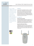
The NJ205 IntelliJack is available in single- and 20-packs. Before
installation, familiarize yourself with the following items, which
are included with the NJ205:
1 NJ205 IntelliJack.
2 Four pairs of M3.5mm screws (two per IntelliJack) for
mounting the IntelliJack to the wall, floor box or office cubicle.
3 Mounting plate (face plate).
1
2
3
4
3
1
2
3
About the NJ205 IntelliJack
Additionally, the following items are shipped with the single
pack:
■
Compact disc containing
■
User Guide and additional informational documents.
■
Configuration Manager software.
All screws are phillips pan head type screws. The type of threads
vary to match the different mounting locations compatible with
the IntelliJack.
■
■
Thread forming screws for mounting into plastic:
■
M3 x 30mm (2x)
■
M3 x 40mm (2x)
Machine screws for mounting into metal:
■
M3.5 x 50mm (2x)
■
M3.5 x 740mm (2x)
For more information on optional components, see Appendix C,
“Optional Components”.
4
NJ205 Description
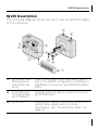
NJ205 Description
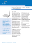
The following diagram shows the front, rear and bottom views
of the IntelliJack:
1
RJ-45 switched
PAN (personal
area network)
ports
Four 10/100 Mbps auto-negotiation ports,
which the NJ205 configures for 10 Mbps or
100 Mbps connections automatically (green
LEDs).
2
Port LEDs and
corresponding
port numbers
Indicate network status of each of the four
RJ-45 PAN ports.
3
RJ-45 LED
Indicates the status of the LAN connection
(white cable, green LED). For more
information, see “Checking the LEDs” on
page 11.
5
Abo ut the NJ 205 IntelliJack
4
Power LED
Indicates NJ205 p ower status (gr een). For
more information, see “Checking the LEDs”
on page 11.
5
Pass-through
port
Provides an independent connection to your
LAN that passes through the NJ205 IntelliJack.
The data or voice traffic is separate from and
unaffected by the NJ205 switch.
6
Powerforwar ding LED
Lights when the IntelliJack is connected to
and forwar ding power to an IEEE802.3af
compliant device. For more infor mation, see
“Chec king the LEDs” on page 11.
7
Local power
supply cable
strain relief
Local power supply cable strain r elief.
8
Power Socket
The NJ205 can be p owered from a local
power supply (available for purchase from
3Com). This is required if your network does
not support Power over Ethernet (PoE).
9
Main Unit
LAN cable
(white)
Connects the NJ2 05 switched RJ-45 ports to
the Ethernet LAN. Make sure the port on the
network switch to whic h the NJ205 is
connected is configured as a standard MDI-X
port.
10 Pass-through
LAN cable
(Black)
6
Connects your pass-through port directly
to the Ethernet LAN. No LED
2
Installing the IntelliJack
Installing the NJ205 IntelliJack consists of the following steps:
1 Set up the power supply.
2 Mount the NJ205 to the wall outlet box.
3 Connect devices to the NJ205.
4 Check the NJ205 LEDs.
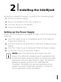
Setting up the Power Supply
Power to the IntelliJack is provided through one of the following
methods:
■ Over the network via an integrated switch that supports
Power Over Ethernet.
■ Over the network via an Ethernet multi-port endspan power
supply.
■ Over the network via a single-port Ethernet power supply.
■ Locally via a 3Com local power supply.
NOTE: Power Over Ethernet, also known as in-line
power, is a method to provide power to equipment over
an Ethernet cable, allowing a device to receive both data
and power from the same network cable. The NJ205 is
ideally powered by a switch that is IEEE 802.3afcompliant. The NJ205 can also be powered by some
switches that are not 802.3af-compliant. Consult the
3Com web site for more information.
7
Installing the IntelliJack
Before you begin installation, determine which type of power
supply the IntelliJack will use. For more information on power
options and configuration, see Appendix D, “Power Options”.
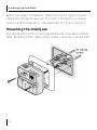
Mounting the IntelliJack
The IntelliJack mounts in any standard British Standard Institute
(BSI): BS 4664:1970 (1986) single cubicle opening or wall outlet.
8
M ounting the IntelliJack
Before connecting the IntelliJack to the network, verify that the
existing network cabling meets the ANSI/TIA/EIA-568 standard
and that the port in the wiring closet is connected to an active
Ethernet MDI-X port.
1 Thread both IntelliJack LAN cables through the opening in
the mounting plate.
2 Connect the wiring as illustrated on page 8.
The IntelliJack has two Ethernet cables each terminated
with a male RJ-45 connector.
The white cable connects the LAN to the four personal
area network (PAN) ports located on the bottom of the
IntelliJack.
The black cable connects the LAN to the single passthrough port located on the front of the IntelliJack.
3 Choose one pair of the provided screws that best fits your
outlet box.
4 Tighten the screws while holding the IntelliJack in place.
NOTE: The IntelliJack is designed to be mounted
using the provided mounting plate or many aftermarket faceplates. However, some after-market
faceplates stand out from the wall and do not
provide a secure mounting surface for the IntelliJack.
In such cases it is recommended to place the 3Com
spacer between the IntelliJack and the after-market
face plate. For more information on the different
mounting plates and spacers, see Appendix B.
9
Installing the IntelliJack
Connecting Devices to the IntelliJack
Once the power source and the data source have been verified in
good working order and the IntelliJack has been installed and
mounted, connect your networking devices (such as computers,
printers, IP phones, cameras, etc.) to the IntelliJack.
The IntelliJack has two ways to connect devices:
1 RJ-45 Personal Area Network (PAN) Ports — any of the four
switched ports on the bottom of the IntelliJack. All ports feature
10/100 Mbps auto-negotiation, which configures the NJ205
IntelliJack for 10 Mbps or 100 Mbps connections automatically.
2 Pass-through port—a single pass-through port is provided
that allows an additional device to be connected to a
separate network segment through the same IntelliJack. The
data or voice traffic that travels through the pass-through
port, passes through the IntelliJack without being switched.
1
2
3
4
10
Checking the LEDs
Checking the LEDs
You can verify the IntelliJack installation by checking the LEDs.
LED
Description
On—the IntelliJack is connected to the network
and a link has been established.
Off—there is no connection to the network.
(LAN)
(Power)
(Powerforwarding)
On—the IntelliJack is receiving power (local or
via the network). When you first connect power
to the IntelliJack, there is a delay of
approximately 5 seconds. The power LED light
blinks once or twice before remaining solid on.
Off—the IntelliJack is not receiving power.
On—the IntelliJack is connected to and is
forwarding power to an IEEE 802.3af-compliant
device.
Off—the IntelliJack is not connected to or is not
forwarding power to an IEEE 802.3af-compliant
device.
CA UTION: Make sure the wiring closet port
connected to the IntelliJack white cable is
configured as a standard MDI-X port.
11
Installing the IntelliJack
12
3
Installing the
Configuration Managers
Once you have installed the NJ205 hardware, you need to
configure it for use on your particular network. To configure the
NJ205, install the Local and Central Configuration Managers.
NOTE: You will use the Local Configuration
Manager for initial configuration of the NJ205
on your network. It is usually easiest if you load
this software on a laptop and use it to configure
NJ205 devices as you install them.
The NJ205 Central Configuration Manager is
used for advanced configuration and
management of one or more NJ205 devices on
your network. This software should be installed
on the machine you plan to use to manage your
NJ205 devices from a remote location—perhaps
the same console you use for SNMP
management.
13
Installing the Configuration Managers
System Requirements
The machine you install the software on should meet the
following requirements:
■ Pentium processor
■ Minimum of 15MB disk space
■ Windows 2000 or Windows NT 4.0 with Service Pack 6
installed (Windows 95 and Windows 98 are not
recommended operating systems for use with management
platforms. In most cases, the Configuration Manager
software will work with Windows 95, 98, or XP. However,
please check 3Com’s web site for additional information
regarding XP support)
Installing the Local and Central Configuration
Managers
To install the Configuration Manager software:
1 Insert the Configuration Manager software CD into your
Windows 2000 or Windows NT computer.
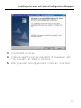
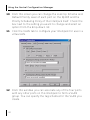
2 If your computer is configured to Auto-Play CDs, the
installation will start automatically. If not, double-click the
setup.exe icon on the CD, and you will see this window:
14
Installing the Local and Central Configuration Managers
3 Click Next to continue.
4 Carefully read the license agreement. If you agree, click
“Yes, I accept” and Next to continue.
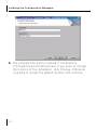
5 Enter your user and organization names and click Next.
15
Installing the Configuration Managers
6 The program files will be installed in the directory
C:\Program Files\3Com\IntelliJack. If you want to change
the location of the installation, click Change. Otherwise
click Next to accept the default location and continue.
16
Installing the Local and Central Configuration Managers
7 Select a typical or custom setup and click Next. The Typical
installation will install both the Local Configuration
Manager and the Central Configuration Manager on your
system. The Custom installation option lets you install just
one of the programs if you wish.
17
Installing the Configuration Managers
8 Review the settings you selected and click the Install button.
18
Installing the Local and Central Configuration Managers
9 When the installation has completed, click the Finish button
to close the installation utility.
The installation utility creates two shortcut icons on the
Desktop--one for the Local Configuration Manager and one
for the Central Configuration Manager.
You can also launch the programs from a program group
you can access from the Start menu. The program group
folder is labeled 3Com IntelliJack and can be found under
the Programs menu.
19
Installing the Configuration Managers
20
4
Using the Local
Configuration Manager
Initializing the NJ205 IntelliJack
Once you have installed the NJ205 hardware on your network
and the Local Configuration Manager software on your
computer, you need to perform an initial configuration of the
IntelliJack.
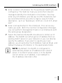
1 Connect your computer to the NJ205 that you are
installing. Attach an Ethernet cable from a computer
running the Local Configuration Manager software to any
one of the four personal area network (PAN) ports on the
front of the NJ205.
2 Click on the desktop shortcut icon labeled NJ205 Local
Config Mgr to start the program. When it launches, you will
see a window like this:
21
Using the Local Configuration Manager
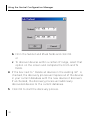
3 The MAC address and default IP address of the currently
connected NJ205 will appear in the first field. If you connect
to another NJ205, you must click the Query button to
refresh the window.
If you are not connected to any IntelliJack, the field will
display the message Not Connected. If the Not Connected
message appears, check your connection to the IntelliJack
and click the Query button.
4 Make sure the General tab is selected.
22
Initializing the NJ205 IntelliJack
5 Enter Location Information for the particular NJ205 you are
configuring. This field can help you and other network
managers identify this IntelliJack in the future. You may
enter any information you like (up to 256 characters), but
we recommend that you enter a logical, easy to follow
description, such as “Building A, 3rd floor, room 315, West
wall.”
6 Enter a Group Name for this IntelliJack. This can be any
name you wish. With the Central Configuration Manager,
you can perform management tasks on all IntelliJacks with
the same group designation.
7 Select the method the NJ205 should use to obtain an IP
address. The NJ205 can either get an IP address from an
existing DHCP server on your network or you can directly
specify the address. If you elect to specify your own
address, you should enter the IP Address, Subnet Mask, and
Default Gateway information in the appropriate fields.
NOTE: By default, the NJ205 is configured to
automatically obtain an IP address from a DHCP
server. If no DHCP server exists, or if the NJ205
cannot obtain an IP address, it will default to
the IP address 192.168.1.252.
23
Using the Local Configuration Manager
8 If you wish, check the box next to Lock IP Address. Selecting
this option will ensure that the IntelliJack will always use a
particular address.
WARNING: If you lock an IP address and
reserve it for this IntelliJack, make sure you
configure your DHCP server so it won’t
distribute that address to other devices.
9 Click the Configure button and the Local Configuration
Manager will ask you to enter the password for the device.
If you haven’t changed the password, you should enter the
default password, which is “password” (without the
quotes). Your changes are sent to the NJ205 and will
become effective immediately.
Those are the only steps required to initialize your NJ205
IntelliJack.
24
Setting Advanced Options
Setting Advanced Options
If you want to change the default password of the NJ205 or
manage it from an SNMP console, you can configure these
settings from either the Local Configuration Manager or the
Central Configuration Manager (covered in the next chapter). In
the Local Configuration Manager, both settings are found under
the Advanced tab.
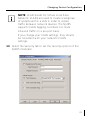
1 Select the Advanced tab on the NJ205 Local Configuration
Manager window.
25
Using the Local Configuration Manager
2 To change the IntelliJack’s configuration password, click on
the box next to Change NJ Password. Then enter the new
password in both password fields. (You must enter the
password twice to ensure you entered it correctly.) The
password you select can be any combination of letters and
numbers between 8 and 32 characters.
3 To configure the NJ205 for management with an SNMP
console, select the SNMP Configuration box. Enter the GET
Community String and SET Community String in the
appropriate fields. Each field lets you enter any combination
of letters and numbers up to 32 characters.
4 Click the Configure button and the Local Configuration
Manager will ask you to enter the password for the device.
If you haven’t changed the password, you should enter the
default password, which is “password” (without the
quotes). Your changes are sent to the NJ205 and will
become effective immediately.
NOTE: You should change the password to
ensure that no one else can re-configure your
system. Make sure you remember the new
password you set. If you forget the new
password, you will not be able to perform
any other configuration tasks unless you
send the device back to 3Com.
26
5
Using the Central
Configuration Manager
You should use the Local Configuration Manager to initialize
each of the NJ205 IntelliJacks installed on your network. Once
you have completed that step, you can manage all of them with
the Central Configuration Manager.
Install this program on any computer on your network you want
to use as a central management console. (See the previous
chapter, “Installing the Configuration Managers,” for help). You
can use the same machine that has your SNMP-based
management platform. The Central Configuration Manager will
be able to configure and manage all of the IntelliJacks that reside
on your network.
Discovering NJ205 Devices on Your Network
In order to manage the NJ205 IntelliJacks on your network, the
Central Configuration Manager needs to include them in its
database. The easiest way to add new NJ205 IntelliJacks to the
database is to use the device discovery tool included in the
Central Configuration Manager. The first time you run the
Central Configuration Manager, it will automatically take you to
the Discovery window as shown under step one below.
27
Using the Central Configuration Manager
To discover devices on your network, run the following steps:
1 Open the Central Configuration Manager by doubleclicking on the NJ205 Central Config Mgr desktop icon.
When it launches, you will see a window similar to this one:
28
Discovering NJ205 Devices on Your Network
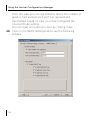
2 Select Discovery from the Devices menu. The following
window appears:
NOTE: The default subnets are the ones your
machine is connected to.
3 You can discover new devices based on a specific subnet or
on a specific range of IP addresses.
a To discover devices by subnet, select that option on the
screen. Click the Add button to add a new subnet to the
discovery list. The following box appears:
29
Using the Central Configuration Manager
b Fill in the Subnet and Mask fields and click OK.
or
c To discover devices within a certain IP range, select that
option on the screen and complete the From and To
fields.
4 If the box next to “Delete all devices in the existing list” is
checked, the discovery process will replace all of the devices
in your current database with the new devices it discovers.
If unchecked, the discovery process will add newly
discovered devices to the current database.
5 Click OK to start the discovery process.
30
Discovering NJ205 Devices on Your Network
The device discovery tool will return the following information
from the NJ205 IntelliJacks on your network:
■
■
■
■
■
■
IP address
MAC address
Subnet address
Group Name
Location information
Firmware version
You can sort this information in ascending or descending order.
NOTE: Discovered devices are automatically
added to the default database. This default
database opens automatically when you launch
the Central Configuration Manager. If you like,
you can keep several database files, each with
its own list of devices. For example, you may
want a separate database for each subnet you
manage. To save a database file or open
another database file, select the Open Database
or Save Database As options from the File
menu.
You can view discovered devices many ways. On the left side of
the window, under the toolbar, you can see a drop down box
with options for either Subnet, Firmware Version, or Group
Name. The option you select in this box determines how the
views are displayed in the left pane of the window.
31
Using the Central Configuration Manager
When Subnet is selected (the default option), you will see a list
of IP subnets to choose from. Selecting Network will show all of
the discovered devices in the database. If you select a particular
subnet, only the devices in that subnet will be displayed.
When Firmware Ver is selected, you will see a list of the different
firmware versions loaded on the devices. This view is particularly
useful if you want to select only the devices with an old firmware
version so you can perform an upgrade.
When you select Group Name from the drop down list, the
Central Configuration Manager will present a list of the different
group names you have specified.
32
Viewing Device Properties
Viewing Device Properties
Once the database is populated with NJ205 IntelliJacks on your
network, you can begin to manage those devices. The main
window of the Central Configuration Manager shows a list of
devices in the current database with the information retrieved
during the discovery process. You can view and configure the
properties for a single NJ205 using this window. To configure
multiple devices at one time, see ““Changing Device
Configuration” on page 39. To get more detailed information
about a device, you should check its properties:
1 Select a IntelliJack from the devices list.
2 Select Property from the Devices menu or from the toolbar.
You can also open this window by right-clicking your
mouse and selecting Property.
33
Using the Central Configuration Manager
3 With the General tab selected, you can view and edit
information about the device such as the IP address, subnet
mask, default gateway, and whether it uses a static IP
address or gets its address from a DHCP server. You can
also view and edit the IntelliJack’s Group Name and
Location information.
4 Click Apply to save any changes you make to the fields in
this window.
34
Viewing Device Properties
5 In the middle of this window you’ll see information about
each of the four PAN ports on the front of the IntelliJack.
You can check to see if the port is Enabled or Disabled, if
there is a network link, whether or not it’s running at half
or full duplex, what speed it’s set for, its priority, and
whether or not it’s part of a virtual network (VLAN).
6 Under the Product Info box, you can see the current
firmware version of the IntelliJack, the Product Name, and
the Serial Number.
7 Click on the Hardware Settings tab to view status
information about the switch.
35
Using the Central Configuration Manager
Several fields in this window can be edited, a few cannot.
You can change the values of the fields with drop-down
lists: Priority Schedule Policy, LAN Port Egress Mode, LAN
Port Ingress Mode, Max Frame Size, Counter Mode, and
Power Forwarding.
8 Simply select the value you wish to change from the dropdown list of options.
36
Viewing Device Properties
NOTE: You can click Apply at any time to save
the changes you have made. But be sure to click
Apply after you have finished making all your
changes.
9 Click on the Statistics tab.
37
Using the Central Configuration Manager
From this view you can see statistics about the number of
good or bad packets each port has received and
transmitted, based on how you have configured the
Counter Mode setting.
You can reset all counters to zero by clicking Clear.
10 Click on the SNMP Settings tab to see the following
window:
38
Changing Device Configuration
You can view and edit the SNMP Common Settings and
Trap Settings for this particular NJ205.
11 Click Apply to save any changes you make and a
configuration summary dialog box will appear. Verify the
information and click OK.
12 Click Exit to close the Device Property window.
Changing Device Configuration
Many of the properties that you can view from the Device
Property windows can be changed from the Device
Configuration window. Here’s how to use this feature:
1 Select one or more IntelliJacks from the devices list.
NOTE: It is possible to configure multiple
IntelliJacks at the same time.
2 Select Configuration from the Devices menu or the toolbar
or right click on a device and select Configuration from the
pop-up menu.
39
Using the Central Configuration Manager
This window has six tabs across the top--General, Priority,
VLAN, Security, SNMP Traps, and Advanced. Check the box
next to any setting you want to change from within these
six areas.
3 Select the General tab.
4 To change or set the Group Name, check the box next to
that field. You can set a Group Name to anything you want,
up to 256 characters.
5 Change or set the Location Name by checking the box next
to that field and entering up to 256 characters.
6 Configure the DHCP setting to the desired state.
40
Changing Device Configuration
7 Change the Port and Link states of any of the IntelliJack’s
ports by checking the box next to the characteristic you
want to modify and selecting a value from the drop list.
8 By default, the Central Configuration Manager will display a
count of good transmissions in the Property window. If you
would rather track errors and collisions, select that option in
the Counter Mode setting.
9 Click the Priority tab along the top of the Device
Configuration window to view these settings:
41
Using the Central Configuration Manager
10 From this screen you can change the Look Up Scheme and
Default Priority Level of each port on the NJ205 and the
Priority Scheduling Policy of the IntelliJack itself. Check the
box next to the setting you want to change and select an
option from the drop-down list.
11 Click the VLAN tab to configure your IntelliJack for use in a
virtual LAN.
12 From this window you can associate any of the four ports
with any other ports on this IntelliJack to form a VLAN
group. You can specify the tag schemes for the VLAN you
create.
42
Changing Device Configuration
.
NOTE: VLAN stands for Virtual Local Area
Network. VLANS are used to create a subgroup
of systems within a LAN in order to isolate
traffic between network devices. The NJ205
supports VLAN tagging, but does not route
inbound traffic on a per-port basis.
If you change your VLAN settings, they should
be consistent with your network’s VLAN
settings.
13 Select the Security tab to set the security options of the
NJ205 IntelliJack.
43
Using the Central Configuration Manager
14 You can change the device password (the default password
is “password”), and adjust the SNMP Set permissions and
Community Strings.
15 Click the SNMP Traps tab to change the trap settings of the
NJ205.
16 From this window you can enable or disable the device’s
Cold Start, Link Down, Link Up, and Authorization Fail traps
to be sent to your SNMP console.
44
Changing Device Configuration
17 Select the Advanced tab for this window:
18 You can change the Max Frame Size and Power Forward
settings by selecting an option from the drop-down list.
19 From this window, you can see another set of tabs, one for
each port on the IntelliJack. Click on the port whose
settings you want to change, check the box next to the
setting to be changed, and select a value from the dropdown list. You can change the Flow Control, the
AutoMDI(X) crossover capabilities, and the Multicast Rate
Limit.
45
Using the Central Configuration Manager
20 At the bottom of this window is an option to restore some
of the configuration settings to their default values. If you
check this box, the following settings will be restored:
Global Setting
Default Value
Max Frame Size
1518 or 1522 if tagged
Counter Mode
Count good frames
Priority Scheduling Mode
8, 4, 2, 1 weighted
VLAN Tag for LAN Port (egress)
Egress frame unmodified
VLAN Tag for LAN Port
(ingress)
Ingress frame unmodified
Power Forward
Auto detection
SNMP “Set” Permission
Not allowed
Port Setting
Default Value
State
Forwarding
Link
Auto negotiation
Flow Control
Off
MDI[X]
Force MDI
Multicast Limit
3%
Priority Lookup
Tag & IPV4
Port Priority
1
VLAN ID
1
Port based VLAN
All ports on same VLAN
46
Changing Device Configuration
■
■
■
■
■
■
■
The values that remain unchanged when you click Restore
Factory Default Settings are:
Group Name
Location ID
Password
IP Address
DHCP Settings
SNMP Community Strings
SNMP Trap Settings
21 When you are finished entering the configuration changes
to your NJ205 IntelliJack, click the OK button and a
Configuration Progress dialog box will appear. If you don’t
want to apply the changes you made, click Exit to discard
those changes and exit the window.
47
Using the Central Configuration Manager
22 If you click Configuration Summary, you will see a summary
of all the changes you have made. Enter your password and
click Start. As the IntelliJacks are configured, their status will
be updated in the Status column.
NOTE: If a NJ205 IntelliJack that was once
discovered by the Central Configuration Manager is
no longer connected to your network or if you just
want to remove a device from the current database,
you can select Delete Device from the Devices menu.
48
Finding Computers Connected to NJ205 Devices
Finding Computers Connected to NJ205 Devices
Occasionally you may need to find out which IntelliJack a
networked device, such as a PC, is connected to. This is one of
the many situations where the Location Information field of the
NJ205 can be very useful.
If you know the IP address or MAC address of the computer or
networked device, you can use the Central Configuration
Manager to find the right IntelliJack.
1 Select Find Location from the Tools menu. You will see a
window like this:
2 Enter the IP address or the MAC address of the network
device you wish to find.
3 Click the Find button.
49
Using the Central Configuration Manager
When the search is complete, the Search Results field will
display the IP address of the NJ205 that the network device
is connected to. It will also show the Location Name
assigned to the IntelliJack and which PAN port the network
device is using.
4 Click OK to close the window.
50
Upgrading the NJ205 Firmware
Upgrading the NJ205 Firmware
You can upgrade the firmware on your NJ205 devices over the
network from the Central Configuration Manager. To do so,
follow these steps:
1 Select one or more IntelliJacks you want to upgrade. You
can select groups of IntelliJacks using one of the grouping
options available to you in the drop-down list at the top left
corner of the main window.
2 Select Upgrade from the devices menu. A window like this
will appear:
3 Select Yes to continue the upgrade operation. A window
like this will appear:
51
Using the Central Configuration Manager
4 Select a valid firmware image by typing the path to the file
or by using the Browse button.
5 Select the time to perform the upgrade. You can either
send the update file immediately or select a specific time
and date to send the file. You may, for example, want to
perform an upgrade during off hours such as a weekend.
6 Click Next and a window like this will appear:
52
Upgrading the NJ205 Firmware
7 Review the list of IntelliJacks you want to upgrade. If you
want to modify this list, click Cancel and restart the
firmware upgrade procedure.
53
Using the Central Configuration Manager
8 Type your password in the Password field, then click Finish.
The Upgrade Progress dialog box will appear.
54
Upgrading the NJ205 Firmware
Viewing Log Files
The Central Configuration Manager creates a log file with details
of the firmware upgrade operation. This file is in the Central
Configurator\Log subdirectory under the directory where you
installed the IntelliJack configuration software. You can also view
a history of firmware upgrades by selecting Log History from the
View menu. A window like this will appear:
To view the details of a particular log, select it and click Detail. If
the firmware upgrade of an NJ205 unit fails for some reason, a
message will appear in the upgrade progress dialog box and the
log file. Consult the troubleshooting guide on page 75 for more
information.
55
Using the Central Configuration Manager
Viewing and Canceling Scheduled Firmware Upgrades
You can select a time and date to send an upgraded firmware
image to the IntelliJacks in your network. To view and make
changes to the firmware upgrades you have scheduled, follow
these steps:
1 Select Scheduled Upgrade from the View menu. A window
like this will appear:
2 To view the details of a scheduled upgrade, select it from
the list and click Show Devices. To cancel a scheduled
upgrade, select it from the list and click Delete.
56
A
Specifications
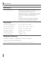
Hardware
Power consumption
<3.5 watts without power forwarding
Maximum 11 watts with power forwarding
(depending on the device drawing power)
Network Interface
10 Mbps Ethernet
10BASE-T
Ethernet IEEE 802.3 industry standard for a
10 Mbps baseband CSMA/CD local area
network
100 Mbps Ethernet
100BASE-TX
Ethernet IEEE 802.3u industry standard for
a 100 Mbps baseband CSMA/CD local area
network
57
Specifications
Performance
Auto-negotiation
Communication speed (10 Mbps or
100 Mbps) and duplex mode (full or half)
can be determined through autonegotiation with the attached devices. The
IntelliJack attempts to negotiate the fastest
connection possible (100 Mbps fullduplex).
The communication speed and duplex
mode can also be controlled using the
configuration management software.
Environment
Operating temperature
32° to 104° F (0° to 40° C)
Storage temperature
-22° to 194° F (-30°- to 90° C)
Operating humidity
10-90% noncondensing
Storage humidity
10-90% noncondensing
Operating Altitude
8,000 ft. max
Storage Altitude
20,000 ft. max
Standards Conformance
IEEE 802.3 10BASE-T, 100BASE-TX and auto-negotiation
Power Over Ethernet IEEE 802.3af
Power forwarding of 7 watts, 48 volts from port number 4
58
Features
Power Over Ethernet
Compatible with IEEE 802.3af
Local power supply
Required for networks that do not support
Power Over Ethernet
Voice Over IP (VoIP)
Compatible with VoIP.
Power forwarding
Power forwarding Port number 4 can be
used with any standard networking device
as well as to power a device such as a VoIP
telephone on a network that uses IEEE
802.3af-compatible Power Over Ethernet.
59
Specifications
60
B
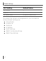
Default Settings
Global Setting
Default Value
Max Frame Size
1518 or 1522 if tagged
Counter Mode
Count good frames
Priority Scheduling Mode
8, 4, 2, 1 weighted
VLAN Tag for LAN Port
(egress)
Egress frame unmodified
VLAN Tag for LAN Port
(ingress)
Ingress frame unmodified
Power Forward
Auto detection
SNMP “Set” Permission
Not allowed
Port Setting
Default Value
State
Forwarding
Link
Auto negotiation
Flow Control
Off
MDI[X]
Force MDI
Multicast Limit
3%
Priority Lookup
Tag & IPV4
61
Default Settings
Port Setting
Default Value
Port Priority
1
VLAN ID
1
Port based VLAN
All ports on same VLAN
The values that remain unchanged when you click Restore
Factory Default Settings are:
■
■
■
■
■
■
■
62
Group Name
Location ID
Password
IP Address
DHCP Settings
SNMP Community Strings
SNMP Trap Settings
C
Optional Components
The IntelliJack works with the following optional components, all
of which are available from 3Com (order online at
www.3com.com).
Pow er Supplies and IP Phone Pow er M odule
Component
Purpose
3C Number(s)
Ethernet Multi-port
Endspan Power
Supply
For providing Power Over
Ethernet to power up to 24
IntelliJacks.
802.3af-compliant integrated
3C17205
Ethernet Multi-port
Midspan Power
Supply
For providing Power Over
Ethernet to power up to 24
IntelliJack devices.
802.3af-compliant
3CNJPSE24
Single-port
Ethernet power
supply
For providing Power Over
Ethernet to locally power a
single IntelliJack.
3CNJPSE
Local power supply
For locally powering a single
IntelliJack; required if your
network does not support
Power Over Ethernet.
3CNJPSL
NBX Phone Power
Module
For powering over Ethernet a
NBX VoIP telephone that uses
Capacitive Power Discovery
Process by an IEEE 802.3af
compliant PSE.
3CNJVOIPNBX
switch
63
Optional Components
Mounting Plates and Spacers
3Com Part
Number
Description
3CNJMP-EXT
10 mm-thick extension ring used to add depth to
wall outlet openings when installing an NJ105 or
NJ205 IntelliJack.
3CNJMPD-UK
Mounting plate that enables the installation of
the NJ105 and NJ205 IntelliJack devices in a UKstyle two- or double-gang box.
3CNJMP-FLR
Mounting plate that enables the installation of
the NJ105 or NJ205 IntelliJack in a “floor box.”
3CNJMP-SPR
Mounting plate used to securely install an NJ105
or NJ205 IntelliJack in wall openings with built-in
trim rings, as found in Spain and other locations.
3CNJMP-FR
Mounting plate that enables the installation of
the NJ105 or NJ205 IntelliJack in a French-style
raceway (locally called “goullot”).
64
D
Pow er Options
The 3CNJ205 IntelliJack is compliant with the following power
options:
IEEE 802.3af PSE (Power Source Equipment)
3Com SuperStack 3 Switch 4400 PW R (3C17205)
3Com Power over Ethernet Multiport Midspan (3CNJPSE24)
3Com Power over Ethernet Single-port Midspan (3CNJPSE)
3Com IntelliJack AC Power Supply (3CNJPSL)
Before you begin the installation, determine which type of
power supply the IntelliJack will use.
NOTE: For additional information on power
supplies that support the IntelliJack, go to
www.3com.com/.
CA UTION: Use only a power supply that is
provided or approved by 3Com with the
IntelliJack. Failure to do so may result in damage
to the IntelliJack, or may result in a hazardous
situation or personal injury.
65
Power Options
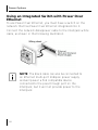
Using an Integrated Switch with Power Over
Ethernet
To use Power Over Ethernet, you must have a switch on the
network that has Power Over Ethernet integrated into it.
Connect the network data/power cable to the IntelliJack white
cable, as shown in the following illustration.
NOTE: The black cable can also be connected to
an Ethernet multi-port midspan power supply
and will power a PoE compatible device
connected to the pass-through port on the
IntelliJack, but it will not provide power to the
IntelliJack.
66
Using Ethernet Multi-port Midspan Power Supply
Using Ethernet Multi-port Midspan Power Supply
To use an Ethernet multi-port midspan power supply, you must
connect the power supply to your network, as shown in the
illustration on page 68.
The Ethernet multi-port midspan power supply from 3Com
connects to an existing Ethernet or Fast Ethernet infrastructure
with standard Category 5 or better cabling, and powers up to 24
IntelliJack devices. For complete installation instructions, see the
Ethernet multi-port midspan power supply documentation
located at www.3Com.com.
Connect the network data/voice/power cable to the IntelliJack
white cable.
Connect the network second data/voice/power cable (if
available) to the IntelliJack black cable.
67
Power Options
NOTE: The black cable can also be connected to
Ethernet multi-port midspan power supply and
will power a PoE compatible device connected
to the pass-through port on the IntelliJack, but
it will not provide power to the IntelliJack.
68
Using a Single-port Ethernet Power Supply
Using a Single-port Ethernet Power Supply
To use a single-port Ethernet power supply, connect the power
supply to the network hub or switch and to the IntelliJack white
cable, as shown in the following illustration. The black cable
should be connected to a data port on the wire closet switch.
69
Power Options
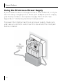
Using the 3Com Local Power Supply
If your network does not support Power Over Ethernet, or if you
are not using a single-port or multi-port endspan power supply,
you must purchase a local power supply from 3Com. See
Appendix C "Obtaining Optional Components".
To power the IntelliJack with a local power supply, make sure
you have an electrical outlet near the site where the IntelliJack
will be installed.
70
Using the 3Com Local Power Supply
To connect the local power supply to the IntelliJack, follow these
steps (as shown in the previous diagram):
1 Route the power cable through the strain relief on the top
of the IntelliJack.
2 Plug the power cable into the IntelliJack.
3 Check to ensure that the cable is secure in the strain relief.
4 Route the cable behind the trim ring from top to bottom.
5 Secure the local power supply and cable to the wall.
6 Plug the local power supply into the power source.
WARNING: Only use the local power supply
available from 3Com. Failure to do so may result
in damage to the IntelliJack, or may result in a
hazardous situation.
71
Power Options
72
E
Installation Planning
Make sure the wall or cubicle opening where the IntelliJack is
being installed complies with the British Standard Institute (BSI):
BS 4664:1970 (1986) standard, as described below.
Make sure the distance between the back of the IntelliJack and
the inside of the wall or cubicle opening is at least 30mm to
maintain an acceptable bend radius on the cable.
73
Installation Planning
WARNING: The NJ205 is designed to be
mounted using the provided mounting plate or
many after-market faceplates. However, some
after-market faceplates stand out from the wall
and do not provide a secure mounting surface
for the IntelliJack. In such cases, it is
recommended to place the 3Com spacer
between the IntelliJack and the after-market
face plate.
To ensure proper horizontal cabling functionality, adhere to the
following standards during installation:
■
■
■
ANSI/TIA/EIA-568
Commercial Building Telecommunications Cabling Standard
ANSI/TIA/EIA-569
Commercial Building Standard for Telecommunications
Pathways and Spaces
BRITISH STANDARD INSTITUTE (BSI): BS 4664:1970 (1986)
The network cabling at your site (from the wiring closet to the
wall or cubicle opening) may already be installed. If it is not,
install the cabling following these general guidelines.
CAUTION: It is recommended that a professional
cable installer perform these procedures. Be sure to
adhere to local safety and regulatory codes during
the cable installation.
74
F
Troubleshooting
If you encounter problems with the NJ205 IntelliJack:
■
■
Verify the IntelliJack is receiving power by viewing the
Power LED (it should be on). If the Power LED is not on,
make sure that:
■
(If using Power Over Ethernet) the other end of the
network cable is plugged into a switch on the network
that has Power Over Ethernet integrated into it, or one
that feeds into an external midspan power supply that
supports Power Over Ethernet.
■
(If using a local power supply) the power supply is
plugged into the IntelliJack and into a working electrical
outlet.
Verify the IntelliJack is connected to the network properly
by viewing the Link LED (it should be on). If the Link LED is
not on, make sure the network cable:
■
Is terminated properly. Refer to the connector
manufacturer’s instructions for terminating the cable. Be
sure to test the connector and verify it is working.
■
Has a valid connection to the network.
■
Adheres to proper length and cabling specifications for
your network.
75
Troubleshooting
Troubleshooting Matrix
Event/
Message
Description
Solution
Power LED is
not on
IntelliJack is not receiving
power
Ensure power supply is
properly connected.
For power over Ethernet,
make sure that the cable is
connected to both the
LAN port on the back of
the IntelliJack and to the
workgroup switch.
Link LED is
not on
IntelliJack has no
connection to the
network
n
n
n
Green LEDs
on Ports 1-4
are not on
Network device has no
connection to IntelliJack
n
n
n
76
Make sure network
cable is properly
terminated.
Make sure the
IntelliJack is
connected to the
network.
Make sure the cable
is plugged into the
workgroup switch.
Make sure the cable
is properly
connected to the
network device.
Make sure the cable
is firmly connected
to one of the four
IntelliJack ports
labeled 1-4.
Make sure the cable
is a good straightthrough cable.
Troubleshooting Matrix
Event/
Message
Description
Amber LED
on Port 4 is
not lit
Power is not being
forwarded to network
device
Solution
n
n
n
n
n
Make sure the cable
is properly
connected to the
network device.
Make sure the cable
is firmly connected
to one of the four
IntelliJack ports
labeled 1-4.
Make sure the cable
is a good straightthrough cable.
Make sure network
device is 802.3af
compatible.
Make sure the
power requirement
for network device
does not exceed 7
watts.
Authenticati
on Failure
Wrong password has
been entered
Confirm correct
password and re-type.
Timeout
Device did not respond
within a specified
period of time
Refresh the screen after
a few seconds. If the
problem persists, try to
rediscover the device.
77
Troubleshooting
Event/
Message
Description
Solution
Attributes
Error
Unexpected
configuration
parameters
Confirm that you have
specified valid
parameter values and
retry the configuration
operation.
NOTE: This error should
not appear to the user
under normal
conditions.
General Error
Something other than
authentication failure,
timeout or attributes
error has occurred
Retry the operation you
were performing.
NOTE: This error should
not appear to the user
under normal conditions.
78
G
Technical Support
3Com provides easy access to technical support information
through a variety of services. This section describes these
services. Information contained in this section is correct at time
of publication. For the most recent information, 3Com
recommends that you access the 3Com Corporation World Wide
Web site: www.3com.com.
90 Day Free Installation Support
3Com provides free installation and troubleshooting telephone
support for this product for 90 days from the date of purchase.
Hours of operation are subject to change. See “Support from
3Com” on page 82.
Online Technical Services
3Com offers worldwide product support 24 hours a day, 7 days
a week, through the following online systems:
■
■
■
World Wide Web site
3Com Knowledgebase Web Services
3Com FTP site
79
Technical Support
World Wide Web Site
To access the latest networking information on the
3Com Corporation World Wide Web site, enter this URL
into your Internet browser: http://www.3com.com/ This service
provides access to online support information, such as technical
documentation and a software library, as well as support options
that range from technical education to maintenance and
professional services.
3Com Knowledgebase Web Services
This interactive tool contains technical product information
compiled by 3Com expert technical engineers around the
globe. Located on the World Wide Web at http://
knowledgebase.3com.com, this service gives all 3Com
customers and partners complementary, around-the-clock
access to technical information on most 3Com products.
3Com FTP Site
Download drivers, patches, software, and MIBs across the
Internet from the 3Com public FTP site. This service is available
24 hours a day, 7 days a week.
To connect to the 3Com FTP site, enter the following
information into your FTP client:
■ Hostname: ftp.3com.com
■ Username: anonymous
■ Password: <your Internet e-mail address>
80
Support from Your Network Supplier
NOTE: You do not need a user name and
password with Web browser software, such as
Netscape Navigator and Microsoft Internet
Explorer.
Support from Your Network Supplier
If you require additional assistance, consult your network
supplier. Many suppliers are authorized 3Com service partners
who are qualified to provide a variety of services, including
network planning, installation, hardware maintenance,
application training, and support services.
When you consult your network supplier, have the following
information ready:
■ Product model name, part number, and serial number
■ A list of system hardware and software, including revision
levels
■ Diagnostic error messages
■ Details about recent configuration changes, if applicable
If you are unable to consult your network supplier, see the
following section on how to contact 3Com.
81
Technical Support
Support from 3Com
If you are unable to obtain assistance from the 3Com online
technical resources or from your network supplier, 3Com offers
technical telephone support services. To find out more about
your support options, call the 3Com technical telephone support
phone number: UK- 0870 909 3266; DE- 01805 404 747.
When you contact 3Com for assistance, have the following
information ready:
■
■
■
■
Product model name, part number, and serial number
A list of system hardware and software, including revision
levels
Diagnostic error messages
Details about recent configuration changes, if applicable
Returning Products for Repair
Before you send a product directly to 3Com for repair, you must
first obtain an authorization number. Products sent to 3Com
without authorization numbers will be returned to the sender
unopened, at the sender’s expense. To obtain an authorization
number, refer to the table on page 83.
82
Technical Support
Country
Telephone #
Austria
01 79567124
Belgium (Flemish)
070 700000
Belgium (French)
070 700770
Denmark
70107289
Finland
01080-2783
France
0825 809 622
Germany
01805 404 747
Hungary
06800 14466
Ireland
1800 509359
Israel
1800 9432632
Italy
199 161346
Luxembourg
800 29880
Netherlands
0900 777 7737
Norway
815 33 047
Poland
00800 4411357
Portugal
707 200 123
South Africa
0800 991196
Spain
9 021 60455
Sweden
0771114453
Switzerland
0848850112
UK
0870 909 3266
All Other Countries
+44 1442 435529
83
Limited Warranty and Regulatory
Compliance Information
3Com Corporation Limited Warranty
This warranty applies to customers located in the United States, Australia, Canada
(except Quebec), Ireland, New Zealand, U.K., and other English language countries,
and countries for which a translation into the local language is not provided.
3Com® NJ205
Hardware
3Com warrants to the end user ("Customer") that this hardware product will be
substantially free from material defects in workmanship and materials, under normal
use and service, for the following length of time from the date of purchase from
3Com or its authorized reseller:
Limited Lifetime, for as long as the original Customer owns the product or for 5 years
after product discontinuance, whichever occurs first (not transferable to a
subsequent end user). FOR NON-US CUSTOMERS: Where a limited lifetime warranty
is not permitted by local law, a 10 year warranty period shall be given by 3Com. The
duration of this warranty shall be modified where necessary to meet any minimum
warranty period required by law.
3Com’s sole obligation under this express warranty shall be, at 3Com’s option and
expense, to repair the defective product or part, deliver to Customer an equivalent
product or part to replace the defective item, or if neither of the two foregoing
options is reasonably available, refund to Customer the purchase price paid for the
defective product. All products that are replaced will become the property of 3Com.
Replacement products or parts may be new or reconditioned. 3Com warrants any
replaced or repaired product or part for ninety (90) days from shipment, or the
remainder of the initial warranty period, whichever is longer.
Limited Warranty and Regulatory Compliance Information
OBTAINING WARRANTY SERVICE
Customer must contact a 3Com Corporate Service Center or an Authorized 3Com
Service Center within the applicable warranty period to obtain warranty service
authorization. Dated proof of purchase from 3Com or its authorized reseller may be
required. A User Service Order (USO), Return Material Authorization (RMA) or Service
Repair Order (SRO) number will be issued. This number must be marked on the
outside of the package sent to 3Com’s Corporate Service Center. The product must
be packaged appropriately for safe shipment and sent prepaid. It is recommended
that returned products be insured or sent by a method that provides for tracking of
the package. Responsibility for loss or damage does not transfer to 3Com until the
returned item is received by 3Com. 3Com will retain risk of loss or damage until the
item is delivered to Customer. For non-US Customers, the word 'prepaid' shall be
omitted where this requirement is not permitted by law. The allocation of
responsibility for loss or damage stated shall be subject to any mandatory legal
requirements. 3Com shall not be responsible for any software, firmware,
information, or memory data of Customer contained in, stored on, or integrated
with any products returned to 3Com for repair, whether under warranty or not.
WARRANTIES EXCLUSIVE, WARRANTY DISCLAIMER
TO THE FULL EXTENT ALLOWED BY LAW, THE FOREGOING WARRANTIES AND
REMEDIES ARE EXCLUSIVE AND ARE IN LIEU OF ALL OTHER WARRANTIES, TERMS
OR CONDITIONS, EXPRESS OR IMPLIED, EITHER IN FACT OR BY OPERATION OF LAW,
STATUTORY OR OTHERWISE, INCLUDING, WITHOUT LIMITATION, WARRANTIES,
TERMS OR CONDITIONS OF MERCHANTABILITY, FITNESS FOR A PARTICULAR
PURPOSE, SATISFACTORY QUALITY, CORRESPONDENCE WITH DESCRIPTION,
NONINFRINGEMENT AND QUIET ENJOYMENT, ALL OF WHICH ARE EXPRESSLY
DISCLAIMED. 3COM NEITHER ASSUMES NOR AUTHORIZES ANY OTHER PERSON TO
ASSUME FOR IT ANY OTHER LIABILITY IN CONNECTION WITH THE SALE,
INSTALLATION, MAINTENANCE OR USE OF THIS PRODUCT.
3COM SHALL NOT BE LIABLE UNDER THIS WARRANTY IF ITS TESTING AND
EXAMINATION DISCLOSE THAT THE ALLEGED DEFECT OR MALFUNCTION IN THE
PRODUCT DOES NOT EXIST OR WAS CAUSED BY CUSTOMER'S OR ANY THIRD
PERSON'S MISUSE, NEGLECT, IMPROPER INSTALLATION OR TESTING,
UNAUTHORIZED ATTEMPTS TO OPEN, REPAIR OR MODIFY THE PRODUCT, OR ANY
OTHER CAUSE BEYOND THE RANGE OF THE INTENDED USE, OR BY ACCIDENT, FIRE,
LIGHTNING, POWER CUTS OR OUTAGES, OTHER HAZARDS, OR ACTS OF GOD.
Limited Warranty and Regulatory Compliance Information
LIMITATION OF LIABILITY
TO THE FULL EXTENT ALLOWED BY LAW, 3COM ALSO EXCLUDES FOR ITSELF AND
ITS LICENSORS AND SUPPLIERS ANY LIABILITY, WHETHER BASED IN CONTRACT OR
TORT (INCLUDING NEGLIGENCE), FOR INCIDENTAL, CONSEQUENTIAL, INDIRECT,
SPECIAL, OR PUNITIVE DAMAGES OF ANY KIND, OR FOR LOSS OF REVENUE OR
PROFITS, LOSS OF BUSINESS, LOSS OF INFORMATION OR DATA, OR OTHER
FINANCIAL LOSS ARISING OUT OF OR IN CONNECTION WITH THE SALE,
INSTALLATION, MAINTENANCE, USE, PERFORMANCE, FAILURE, OR INTERRUPTION
OF ITS PRODUCTS, EVEN IF 3COM OR ITS AUTHORIZED RESELLER HAS BEEN
ADVISED OF THE POSSIBILITY OF SUCH DAMAGES, AND LIMITS ITS LIABILITY TO
REPAIR, REPLACEMENT, OR REFUND OF THE PURCHASE PRICE PAID, AT 3COM'S
OPTION. THIS DISCLAIMER OF LIABILITY FOR DAMAGES WILL NOT BE AFFECTED IF
ANY REMEDY PROVIDED HEREIN SHALL FAIL OF ITS ESSENTIAL PURPOSE.
Some countries, states, or provinces do not allow the exclusion or limitation of
implied warranties or the limitation of incidental or consequential damages for
certain products supplied to consumers, or the limitation of liability for death or
personal injury, so the above limitations and exclusions may be limited in their
application to you. When the implied warranties are not allowed to be excluded in
their entirety, they will be limited to the duration of the applicable written warranty.
This warranty gives you specific legal rights which may vary depending on local law.
GOVERNING LAW
This Limited Warranty shall be governed by the laws of the State of California,
U.S.A., and by the laws of the United States, excluding their conflicts of laws
principles. The United Nations Convention on Contracts for the International Sale of
Goods is hereby excluded in its entirety from application to this Limited Warranty.
3Com Corporation
5500 Great America Pkwy
Santa Clara, California
95052-8145
U.S.A. (408) 326-5000
Limited Warranty and Regulatory Compliance Information
FCC Class A Verification Statement
WARNING: This equipment has been tested and found to comply with the limits for a
Class A digital device, pursuant to Part 15 of the FCC Rules, and the Canadian
Department of Communications Equipment Standards entitled, “Digital Apparatus,”
ICES-003. These limits are designed to provide reasonable protection against harmful
interference in a commercial installation. This equipment generates, uses and can
radiate radio frequency energy and, if not installed and used in accordance with the
instructions, may cause harmful interference to radio communications. Operation of
this equipment in a residential area is likely to cause harmful interference, in which
case, the user will be required to correct the interference at the user’s own expense.
Changes or modifications not expressly approved by 3Com could void the user’s
authority to operate this equipment.
FCC Declaration of Conformity
We declare under our sole responsibility that the
Model:
Description:
3CNJ205
NJ205 IntelliJack
to which this declaration relates, is in conformity with the following standards or
other normative documents:
ANSI C63.4-1992 Methods of Measurement
Federal Communications Commission 47 CFR Part 15, subpart B
European Union Declaration of Conformity
This product is in compliance with the essential requirements and other relevant
provisions of Directives 73/23/EEC and 89/336/EEC.
3Com Corporation - 5500 Great America Pkwy - Santa Clara, California - 950528145 - U.S.A.
3Com Corporation
P.O. Box 58145
5500 Great A merica Pkwy
Santa Clara, CA 95052-8145
U.S.A .
www.3com.com