1
Installation Guide
NJ100 Network Jack
3CNJ100
4-port 10/100 Mbps Unmanaged
Ethernet Switch
http://www.3com.com/
http://www.3com.com/productreg
09-2141-000
Published September 2001
3Com Corporation ■ 5400 Bayfront Plaza
Santa Clara, California ■ 95052-8145 ■ U.S.A.
Copyright © 2001 3Com Corporation. All rights reserved. No part of this
documentation may be reproduced in any form or by any means or used to
make any derivative work (such as translation, transformation, or adaptation)
without written permission from 3Com Corporation.
3Com Corporation reserves the right to revise this documentation and to make
changes in content from time to time without obligation on the part of 3Com
Corporation to provide notification of such revision or change.
3Com Corporation provides this documentation without warranty, term, or
condition of any kind, either implied or expressed, including, but not limited
to, the implied warranties, terms or conditions of merchantability, satisfactory
quality, and fitness for a particular purpose. 3Com may make improvements or
changes in the product(s) and/or the program(s) described in this
documentation at any time.
If there is any software on removable media described in this documentation, it
is furnished under a license agreement included with the product as a separate
document, in the hard copy documentation, or on the removable media in a
directory file named LICENSE.TXT or !LICENSE.TXT. If you are unable to locate a
copy, please contact 3Com and a copy will be provided to you.
UNITED STATES GOVERNMENT LEGEND
If you are a United States government agency, then this documentation and
the software described herein are provided to you subject to the following:
All technical data and computer software are commercial in nature and
developed solely at private expense. Software is delivered as “Commercial
Computer Software” as defined in DFARS 252.227-7014 (June 1995) or
as a “commercial item” as defined in FAR 2.101(a) and as such is provided
with only such rights as are provided in 3Com’s standard commercial license
for the software. Technical data is provided with limited rights only as provided
in DFAR 252.227-7015 (Nov 1995) or FAR 52.227-14 (June 1987), whichever
is applicable. You agree not to remove or deface any portion of any legend
provided on any licensed program or documentation contained in, or delivered
to you in conjunction with, this user guide.
Unless otherwise indicated, 3Com registered trademarks are registered in the
United States and may or may not be registered in other countries.
3Com is a registered trademark and the 3Com logo is a trademark of
3Com Corporation. All other company and product names may be trademarks
of the respective companies with which they are associated.
Contents
About the Network Jack 2
Before You Begin 6
Obtaining Optional Components 7
Installing the Network Jack 8
Setting up the Power Supply 10
Using an Integrated Switch with Power Over
Ethernet 10
Using a Multi-port Ethernet Power Supply 10
Using a Single-port Ethernet Power Supply 12
Using the 3Com Local Power Supply 12
Setting the Power Over Ethernet Dip Switches 13
Installing the Adapter Plate and Pass-Through Ports
Planning the Installation 17
Setting up the Network Cabling at Your Site 19
Connecting the Network Jack to the Network 19
Mounting the Network Jack 22
Connecting the Local Power Supply (Optional) 23
Connecting Devices to the Network Jack 23
Checking the LEDs 24
Troubleshooting the Network Jack 24
Specifications 26
15
Contents
Contacting Technical Support 28
One-Year Free Installation Support 28
Online Technical Services 29
World Wide Web Site 29
3Com Knowledgebase Web Services 29
3Com FTP Site 30
Support from Your Network Supplier 30
Support from 3Com 31
Returning Products for Repair 31
3Com Corporation Limited Warranty 33
FCC Class A Verification Statement 37
FCC Declaration of Conformity 37
Installation Guide
The 3Com Network Jack is a 4-port, unmanaged Ethernet switch
that fits into any standard electrical wall outlet or data port
opening.
The Network Jack brings switching capabilities to any single port
on an Ethernet network by allowing up to four networking
devices, such as computers, printers, Voice Over IP (VoIP)
telephones, and scanners, to be connected to the network via
one Ethernet port. Optional connectors are also available that
allow up to two additional devices to be connected to separate
network segments through the same Network Jack.
The Network Jack needs no software to operate and little or no
configuration. All ports feature 10/100 Mbps auto-negotiation,
which configures the Network Jack for 10 Mbps or 100 Mbps
connections automatically.
Power to the Network Jack can be provided one of the following ways:
■ Over the network via an integrated switch that supports
Power Over Ethernet; specifically, a switch that is compatible
with Capacitive Power Discovery Process (24V or 48V) or IEEE
802.3af-compatible Power Over Ethernet. Power Over
Ethernet, also known as in-line power, is a feature that
provides power onto an Ethernet cable, allowing a device to
receive both data and power from the same network cable.
■ Over the network via an optional single-port or multi-port
Ethernet power supply. See “Setting up the Power Supply”
on page 10 for more information.
■ Locally via an optional local power supply. See “Using the
3Com Local Power Supply” on page 12 for more information.
1
Installation Guide
About the Network Jack
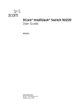
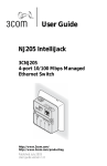
The following diagram shows the front view of the Network Jack.
2
1
2
1
3
4
3
4
5
2
About the Network Jack
1 Switched ports
Allow up to four devices to be connected to
the network.
Port number 1 is also a power-forwarding port;
it can be used with any standard networking
device as well as to power a VoIP telephone on
a network that uses IEEE 802.3af-compatible
Power Over Ethernet.
2 Slot for adapter
plate
Can be fitted with an adapter plate, which
can be installed with up to two pass-through
ports.
3 Adapter plate
with installed
pass-through
port connector
Can be used for voice or other networking
applications. The port bypasses the
functionality of the switch, allowing you to
set up a connection to a separate network
segment or to connect to an analog or digital
PBX telephone.
The adapter plates are available from 3Com.
However, you must purchase the connectors
from the manufacturer. See “Installing the
Adapter Plate and Pass-Through Ports” on
page 15 for more information.
4 LEDs
Indicates network connection status.
Indicates power status.
5 Power socket
Can be used to power the Network Jack with
a local power supply (available for purchase
from 3Com); required if your network does
not support Power Over Ethernet.
3
Installation Guide
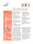
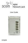
The following diagram shows the back view of the Network Jack.
Ne
tw
or
Mod k In
terfa
el
3C
ce
No
SE 3000
de
MBL
ED
IN
U.S.
A.
4
AS
2
Te
sted
wi
th
to
Co
m
FC
C St ply
an
da
rds
C
US
1
3
4
About the Network Jack
1 Ethernet uplink Connects the Network Jack to the network.
port
Make sure the port on the network switch
to which the Network Jack is connected is
configured as a standard MDI-X port.
2 Slot for adapter Can be fitted with an adapter plate, which can
plate
be installed with up to two pass-through ports.
3 Adapter plate
with installed
pass-through
port connector
Connects the installed pass-through port to
the network.
4 Dip switches
Determine the type of Power Over Ethernet
(Capacitive Power Discovery Process 24V or
48V or IEEE 802.3af) the Network Jack uses.
Setting the dip switches is required only if your
network supports Power Over Ethernet, or if
you are using a multi-port Ethernet power
supply. See “Setting the Power Over Ethernet
Dip Switches” on page 13 for instructions.
5
Installation Guide
Before You Begin
Before you begin installation, register your product at:
www.3com.com/productreg.
The Network Jack is available in single- and 20-packs. Before you
begin the installation, make sure you have the following items,
which are included with the Network Jack:
■
■
■
6x32 screws (2 per Network Jack) for mounting the
Network Jack to the wall or office cubicle.
RJ-45 coupler cable (1 per Network Jack) for connecting
the Ethernet cable from the network to the Network Jack
(required only if your network cable is terminated with a
female RJ-45 connector).
Installation guide (1 per package).
Additionally, the following items are shipped with the single pack:
■ Adapter plates for installing connectors to use as passthrough ports. The adapter plates accommodate connectors
from suppliers including:
■
Panduit (RJ-45 and RJ-11)
■
Avaya (RJ-45 and RJ-11)
NOTE: The connectors for the adapter plates must be
purchased from the manufacturer. For a list of supported
connectors, go to www.3com.com/.
■
6
Adapter plate screws (2) for mounting the adapter plate to
the Network Jack.
Obtaining Optional Components
Obtaining Optional Components
The Network Jack works with the following optional components,
all of which are available from 3Com. Order online at
www.3com.com or by calling 1-877-949-3266.
Component
Purpose
3C Number(s)
Adapter plates
For installing pass-through port
3CNJAP-PA-20
connectors of your choice that allow 3CNJAP-AV-20
a direct connection to another
network segment or for connecting
an analog or digital PBX telephone.
Extension ring
For ensuring that the Network Jack 3CNJEXTRING
is properly mounted to a cubicle;
required if the cubicle opening:
■ Has a depth of fewer than
1.5 inches.
■ Does not support the NEMAWD6 standard.
■ Does not have pre-drilled
screw holes for standard
mounting.
Single-port
Ethernet power
supply
For providing Power Over Ethernet
to locally power a single Network
Jack.
3CNJPSE
Multi-port
Ethernet power
supply
For providing Power Over Ethernet
to power up to 24 Network Jacks.
3CNJPSE24
3C10220
3C10222
Local power
supply
For locally powering a single
Network Jack; required if your
network does not support Power
Over Ethernet.
3CNJPSL
7
Installation Guide
Component
Purpose
3C Number(s)
VoIP telephone
power cable
For powering a VoIP telephone on a Check the 3Com
network that uses Capacitive Power web site
Discovery Process-compatible Power
Over Ethernet.
Network Jack
Tester
For verifying the Network Jack
installation; useful if installing
multiple Network Jacks.
3CNJTESTER
Installing the Network Jack
Installing the Network Jack consists of the following steps:
1 Set up the power supply (page 10).
2 Set the Power Over Ethernet dip switches (page 13;
optional, required only if your network supports Power
Over Ethernet or if you are using a single-port or multi-port
power supply).
3 Install the adapter plate and pass-through ports (page 15;
optional).
4 Plan the installation (page 17).
5 Set up the network cabling at your site (page 19).
6 Connect the Network Jack to the network (page 19).
7 Mount the Network Jack to the wall or office cubicle
(page 22).
8
Installing the Network Jack
8 Connect the local power supply (page 23; optional) not
required if your network supports Power Over Ethernet or
if you are using a single-port or multi-port power supply).
9 Connect network devices to the Network Jack (page 23).
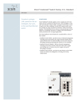
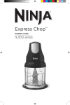
The following diagram displays an overview of the recommended
installation, where the Network Jack is being connected to an
Ethernet network cable that is terminated with a female RJ-45
connector. Detailed installation instructions are included in the
sections that follow.
Wall
To wiring
closet
Network
cable
1
2
3
4
RJ-45
coupler cable
9
Installation Guide
Setting up the Power Supply
Power to the Network Jack can be supplied one of the following ways:
■ Over the network via an integrated switch that supports
Power Over Ethernet.
■ Over the network via a multi-port Ethernet power supply.
■ Over the network via a single-port Ethernet power supply.
■ Locally via a 3Com local power supply.
Before you begin the installation, determine which type of
power supply the Network Jack will use.
NOTE: For a list of power supplies that support the
Network Jack, go to www.3com.com/.
Using an Integrated Switch with Power Over Ethernet
To use Power Over Ethernet, you must have a switch on the
network that has Power Over Ethernet integrated into it. You
must then determine if it is compatible with Capacitive Power
Discovery Process (24V or 48V) or IEEE 802.3af.
Using a Multi-port Ethernet Power Supply
To use a multi-port Ethernet power supply, you must connect the
power supply to your network, as shown in the illustration on
page 11.
10
Installing the Network Jack
The multi-port Ethernet power supply from 3Com connects
to an existing Ethernet or Fast Ethernet infrastructure with
standard Category 5 or Category 5e UTP cabling, and powers
up to 24 Network Jacks. See “Obtaining Optional Components”
on page 7 for ordering information. For complete installation
instructions, see the multi-port Ethernet power supply
documentation.
Network
switch
Wiring closet
To network
hub/switch
To
Network
Jack
1
2
Multi-port Ethernet
power supply
3
4
11
Installation Guide
Using a Single-port Ethernet Power Supply
To use a single-port power supply, connect the power supply to
the network hub or switch and to the Network Jack, as shown in
the following illustration. See “Obtaining Optional Components”
on page 7 for ordering information. For complete installation
instructions, see the single-port Ethernet power supply
documentation.
Network
switch
Wiring closet
To electrical
outlet
To network
hub/switch
To
Network
Jack
1
2
3
4
Using the 3Com Local Power Supply
To use the local power supply, make sure you have an electrical
outlet near the site where the Network Jack will be installed.
12
Installing the Network Jack
Setting the Power Over Ethernet Dip Switches
If your network switch or power supply supports Power Over
Ethernet, you must set the dip switches on the Network Jack
to the appropriate setting: Capacitive Power Discovery/24V,
Capacitive Power Discovery/48V, or IEEE 802.3af.
NOTE: If you are not using Power Over Ethernet to
power the Network Jack, skip this section. Go to
“Installing the Adapter Plate and Pass-Through Ports”
on page 15 to continue.
WARNING: Before setting the dip switches, make sure
that power to the Network Jack is off.
Do not change dip switches 1 and 2 from their factory
default settings (OFF). Changing these settings may
result in performance degradation.
1 On the back of the Network Jack, remove the dip switch cover.
Dip switch cover
Ne
two
rk
Mo
Int
erf
del
ace
3C
AS
No
SE 3000
de
MB
LE
D IN
U.S
.A.
Tes
ted
to
h FC Comp
C Sta ly
nd
ard
wit
s
C
US
13
Installation Guide
2 Set the appropriate dip switches (labeled 3 and 4) for the
type of Power Over Ethernet supported. The default setting
is IEEE 802.3af-compatible Power Over Ethernet.
Power Over Ethernet Supported
Capacitive Power Discovery/24V Ethernet
Power Source
Capacitive Power Discovery/48V Ethernet
Power Source
IEEE 802.3af-compatible Power Over
Ethernet
Dip Switch
Numbers
Setting
4 (ON)
3 (ON)
ON
4
3
2
1
ON
4
3
2
1
4 (ON)
3 (OFF)
4 (OFF)
3 (OFF)
ON
3 Replace the dip switch cover.
14
4
3
2
1
Installing the Network Jack
Installing the Adapter Plate and Pass-Through Ports
If you want to install the blank adapter plate, or if you want to
use pass-through ports for connecting an analog or PBX digital
telephone or for setting up a connection to a separate network
segment, purchase supported connectors and install them on
the appropriate Network Jack adapter plate (included with the
single pack; available for purchase separately with the 20-pack).
For a list of connectors that are supported with the Network Jack
adapter plates, go to www.3com.com.
NOTE: If you are not planning on installing the adapter
plate and pass-through ports, skip this section. Go to
“Planning the Installation” on page 17 to begin the
installation.
1 Pull the network cable(s) from the wiring closet to the
location of the Network Jack.
15
Installation Guide
2 Thread the network cable(s) through the empty slot on the
Network Jack.
Wall
To wiring
closet
3 Terminate the end of the network cable(s) with the
connector(s) you purchased separately.
Refer to the connector manufacturer’s instructions for
terminating the cable. Be sure to test end-to-end system
functionality and verify that it is working.
4 Snap the connector(s) into the appropriate adapter plate.
Each adapter plate is labeled with the name of a connector’s
manufacturer. Be sure to use the adapter plate that matches
the manufacturer of your connector(s).
5 Mount the adapter plate to the Network Jack using the two
adapter plate screws provided.
16
Installing the Network Jack
Planning the Installation
When installed, the back of the Network Jack extends into a wall
or cubicle opening 1.5 inches. Because the depth of some wall
and cubicle openings differ, observe the following requirements
and recommendations before installing the Network Jack:
■ Make sure the wall or cubicle opening where the Network
Jack is being installed complies with the NEMA-WD6
standard, as described below.
1.750"
(44.45 mm)
2.8125"
(71.44 mm)
3.28125"
(83.31 mm)
reference
Screw holes
17
Installation Guide
■
Make sure the distance between the back of the Network
Jack and the inside of the wall or cubicle opening is at least
1.5 inches (3 inches is recommended).
NOTE: Some cubicle openings have a depth of 1.2
inches. In this case, install the Network Jack using the
extension ring (available for purchase separately; see
“Obtaining Optional Components” on page 7) to obtain
the minimum 1.5-inch depth.
If installing into a wall junction box, make sure there is
enough space between the back of the Network Jack and
the inside of the junction box to maintain an acceptable
bend radius on the cable. If you encounter interference
or need additional clearance between the Network Jack
and where it sits inside the junction box, use the
extension ring.
■
18
To ensure proper horizontal cabling functionality, adhere to
the following network cabling standards during installation:
ANSI/TIA/EIA-568
■
Commercial Building Telecommunications Cabling Standard
■
ANSI/TIA/EIA-569
Commercial Building Standard for Telecommunications
Pathways and Spaces
Installing the Network Jack
Setting up the Network Cabling at Your Site
The network cabling at your site (from the wiring closet to the
wall or cubicle opening) may already be installed. If it is not,
install the cabling following these general guidelines.
CAUTION: It is recommended that a professional cable
installer performs these procedures. Be sure to adhere
to local safety and regulatory codes during the cable
installation.
1 Connect one end of an Ethernet cable to your network.
Usually, this connection is done in a network wiring closet,
via the patch panel.
2 Terminate the other end of the cable at the location where
the Network Jack is being installed (using either a female or
male RJ-45 connector).
Refer to the connector manufacturer’s instructions for
terminating the cable. Be sure to test the connector and
verify it is working.
Connecting the Network Jack to the Network
The method for connecting the Network Jack to the network
is determined by how your network cable is terminated (as
described in the previous section, “Setting up the Network
Cabling at Your Site”).
CAUTION: Make sure the port on the network switch to
which the Network Jack is connected is configured as a
standard MDI-X port.
19
Installation Guide
■
If the end of the cable is terminated with a female RJ-45
connector, use the RJ-45 coupler cable included in the
package to connect the Network Jack to the network cable
(recommended installation.)
Wall
To wiring
closet
Network
cable
1
2
3
4
20
RJ-45
coupler cable
Installing the Network Jack
■
If the end of the cable is terminated with a male connector,
connect the network cable directly into the Ethernet
uplink port.
Wall
To wiring
closet
1
2
3
4
Network
cable
21
Installation Guide
Mounting the Network Jack
After connecting the Network Jack to the network, use the two
provided screws to mount the Network Jack in any standard
NEMA-WD6 cubicle opening or wall outlet.
If the cubicle or wall opening has a depth of fewer than five
inches, does not support the NEMA-WD6 standard, or does not
have pre-drilled screw holes, mount the Network Jack using the
extension ring, as shown below.
Wall
Wall
1.5"
1.2"
Extension ring
.3"
Standard
wall mount
Extension ring
wall mount
NOTE: Make sure the vents along the edges of the
Network Jack faceplate are clear of any obstructions.
22
Installing the Network Jack
Connecting the Local Power Supply (Optional)
If your network does not support Power Over Ethernet, or if you
are not using a single-port or multi-port Ethernet power supply,
you must purchase a local power supply from 3Com (see
“Obtaining Optional Components” on page 7). Plug the local
power supply into the power connector located on the bottom
of the Network Jack, and then plug it into any standard electrical
outlet.
CAUTION: Use the local power supply available from
3Com. Failure to do so may result in damage to the
Network Jack, or may result in a hazardous situation.
Connecting Devices to the Network Jack
After the Network Jack is installed and mounted, connect your
networking devices (such as computers, printers, etc.) to any of
the four switched ports on the front of the Network Jack.
If you installed the adapter plate with pass-through ports,
connect the appropriate device(s) to the port(s).
23
Installation Guide
Checking the LEDs
You can verify the Network Jack installation by checking the LEDs.
LED
Description
■
■
On—The Network Jack is connected to the network
and a link has been established.
Off—There is no connection to the network.
(LAN)
■
■
On—The Network Jack is receiving power (local or
via the network).
Off—The Network Jack is not receiving power.
(Power)
Troubleshooting the Network Jack
If you encounter problems with the Network Jack:
■ Verify the Network Jack is receiving power by viewing the Power
LED (it should be lit). If the Power LED is not lit, make sure the:
■
Power Over Ethernet dip switches are set correctly (for
either Capacitive Power Discovery Process 24V or 48V
or IEEE 802.3af), if your network supports
Power Over Ethernet. See “Setting the Power Over
Ethernet Dip Switches” on page 13 for instructions.
24
Troubleshooting the Network Jack
■
■
If using Power Over Ethernet, make sure the
other end of the network cable is plugged into a
switch on the network that has Power Over
Ethernet integrated into it, or one that feeds into
an external midspan power supply that supports
Power Over Ethernet.
■
Local power supply is plugged into the Network Jack and
into a working electrical outlet, if your network does not
support Power Over Ethernet.
Verify the Network Jack is connected to the network
properly by viewing the Link LED (it should be lit). If the
Link LED is not lit, make sure the network cable:
■
Is terminated properly. Refer to the connector
manufacturer’s instructions for terminating the cable.
Be sure to test the connector and verify it is working.
■
Has a valid connection to the network.
■
Adheres to proper length and cabling specifications for
your network.
Make sure the port on the switch to which the Network Jack
is connected is configured as a standard MDI-X port.
25
Installation Guide
Specifications
.80"
1.50"
4.50"
2.75"
2.30"
Hardware
Power consumption
5 watts without power forwarding
Maximum 13 watts with power forwarding
(depending on the device drawing power)
Network Interface
10 Mbps Ethernet
10BASE-T
Ethernet IEEE 802.3 industry standard for
a 10 Mbps baseband CSMA/CD local area
network
100 Mbps Ethernet
100BASE-TX
Ethernet IEEE 802.3u industry standard for
a 100 Mbps baseband CSMA/CD local area
network
26
Specifications
Performance
Auto-negotiation
Communication speed (10 Mbps or 100 Mbps)
and duplex mode (full or half) is determined
through auto-negotiation with the attached
devices. The Network Jack attempts to negotiate
the fastest connection possible (100 Mbps
full-duplex).
Environment
Operating temperature 32˚ to 104˚ F (0˚ to 40˚ C)
Storage temperature
-22˚ to 194˚ F (-3˚- to 90˚ C)
Operating humidity
10-90% noncondensing
Storage humidity
10-90% noncondensing
Operating Altitude
8,000 ft
Storage Altitude
20,000 ft
Standards Conformance
IEEE 802.3 10BASE-T, 100BASE-TX and auto-negotiation
Power Over Ethernet (Capacitive Power Discovery Process and IEEE 802.3af)
Power forwarding (IEEE 802.3; 6 watts, 48 volts)
27
Installation Guide
Features
Power Over Ethernet
Compatible with IEEE 802.3af and Capacitive
Power Discovery Process
Local power supply
Required for networks that do not support Power
Over Ethernet
Voice Over IP (VoIP)
Compatible with VoIP standard.
Power forwarding
Port number 1 can be used with any standard
networking device as well as to power a VoIP
telephone on a network that uses IEEE 802.3afcompatible Power Over Ethernet.
Contacting Technical Support
3Com provides easy access to technical support information
through a variety of services. This appendix describes these services.
Information contained in this appendix is correct at time of
publication. For the most recent information, 3Com recommends
that you access the 3Com Corporation World Wide Web site.
One-Year Free Installation Support
3Com provides free installation and troubleshooting telephone
support for this product for one (1) year from the date of purchase.
Hours of operation are subject to change. See “Support from
3Com” on page 31.
28
Contacting Technical Support
Online Technical Services
3Com offers worldwide product support 24 hours a day, 7 days
a week, through the following online systems:
■ World Wide Web site
■ 3Com Knowledgebase Web Services
■ 3Com FTP site
World Wide Web Site
To access the latest networking information on the 3Com
Corporation World Wide Web site, enter this URL into your
Internet browser: http://www.3com.com/
This service provides access to online support information, such
as technical documentation and a software library, as well as
support options that range from technical education to
maintenance and professional services.
3Com Knowledgebase Web Services
This interactive tool contains technical product information
compiled by 3Com expert technical engineers around
the globe. Located on the World Wide Web at http://
knowledgebase.3com.com, this service gives all 3Com
customers and partners complementary, around-the-clock
access to technical information on most 3Com products.
29
Installation Guide
3Com FTP Site
Download drivers, patches, software, and MIBs across the
Internet from the 3Com public FTP site. This service is available
24 hours a day, 7 days a week.
To connect to the 3Com FTP site, enter the following
information into your FTP client:
■ Host name: ftp.3com.com
■ User name: anonymous
■ Password: <your Internet e-mail address>
NOTE: You do not need a user name and password with
Web browser software, such as Netscape Navigator and
Microsoft Internet Explorer.
Support from Your Network Supplier
If you require additional assistance, consult your network
supplier. Many suppliers are authorized 3Com service partners
who are qualified to provide a variety of services, including
network planning, installation, hardware maintenance,
application training, and support services.
When you contact your network supplier for assistance, have the
following information ready:
■ Product model name, part number, and serial number
■ A list of system hardware and software, including revision levels
■ Diagnostic error messages
■ Details about recent configuration changes, if applicable
If you are unable to consult your network supplier, see the
following section on how to contact 3Com.
30
Contacting Technical Support
Support from 3Com
If you are unable to obtain assistance from the 3Com online
technical resources or from your network supplier, 3Com offers
technical telephone support services. To find out more about
your support options, call the 3Com technical telephone support
phone number:
1 800 527 8677
When you contact 3Com for assistance, have the following
information ready:
■ Product model name, part number, and serial number
■ A list of system hardware and software, including revision levels
■ Diagnostic error messages
■ Details about recent configuration changes, if applicable
Returning Products for Repair
Before you send a product directly to 3Com for repair, you must
first obtain an authorization number. Products sent to 3Com
without authorization numbers will be returned to the sender
unopened, at the sender’s expense. To obtain an authorization
number, call:
1 800 527 8677
31
Limited Warranty and Regulatory
Compliance Information
3Com Corporation Limited Warranty
This warranty applies to customers located in the United States, Australia, Canada
(except Quebec), Ireland, New Zealand, U.K., and other English language countries,
and countries for which a translation into the local language is not provided
3Com® Network Jack
HARDWARE
3Com warrants to the end user ("Customer") that this hardware product will be
substantially free from material defects in workmanship and materials, under normal
use and service, for the following length of time from the date of purchase from
3Com or its authorized reseller:
Limited Lifetime, for as long as the original Customer owns the product or for 5
years after product discontinuance, whichever occurs first (not transferable to a
subsequent end user). FOR NON-US CUSTOMERS: Where a limited lifetime warranty
is not permitted by local law, a 10 year warranty period shall be given by 3Com. The
duration of this warranty shall be modified where necessary to meet any minimum
warranty period required by law.
3Com’s sole obligation under this express warranty shall be, at 3Com’s option and
expense, to repair the defective product or part, deliver to Customer an equivalent
product or part to replace the defective item, or if neither of the two foregoing
options is reasonably available, refund to Customer the purchase price paid for the
defective product. All products that are replaced will become the property of 3Com.
Replacement products or parts may be new or reconditioned. 3Com warrants any
replaced or repaired product or part for ninety (90) days from shipment, or the
remainder of the initial warranty period, whichever is longer.
SOFTWARE
3Com warrants to Customer that each software program licensed from it, except as
noted below, will, if operated as directed in the user documentation, substantially
achieve the functionality described in the user documentation for a period of ninety (90)
days from the date of purchase from 3Com or its authorized reseller. No updates or
upgrades are provided under this warranty. 3Com's sole obligation under this express
warranty shall be, at 3Com's option and expense, to refund the purchase price for the
Limited Warranty and Regulatory Compliance Information
software product or replace the software product with software which meets the
requirements of this warranty as described above. Customer assumes responsibility for
the selection of the appropriate programs and associated reference materials.
3Com makes no warranty or representation that its software products will meet
Customer’s requirements or work in combination with any hardware or software
products provided by third parties, that the operation of the software products will
be uninterrupted or error free, or that all defects in the software products will be
corrected. For any third party products listed in the 3Com software product
documentation or specifications as being compatible, 3Com will make reasonable
efforts to provide compatibility, except where the non-compatibility is caused by a
"bug" or defect in the third party's product or from use of the software product not
in accordance with 3Com’s published specifications or user manual.
THIS 3COM PRODUCT MAY INCLUDE OR BE BUNDLED WITH THIRD PARTY
SOFTWARE. THE WARRANTY PROVISIONS OF THIS DOCUMENT DO NOT APPLY TO
SUCH THIRD PARTY SOFTWARE. IF A SEPARATE END USER LICENSE AGREEMENT
HAS BEEN PROVIDED FOR SUCH THIRD PARTY SOFTWARE, USE OF THAT
SOFTWARE WILL BE GOVERNED BY THAT AGREEMENT. FOR ANY APPLICABLE
WARRANTY, PLEASE REFER TO THE END USER LICENSE AGREEMENT GOVERNING
THE USE OF THAT SOFTWARE.
OBTAINING WARRANTY SERVICE
Customer must contact a 3Com Corporate Service Center or an Authorized 3Com
Service Center within the applicable warranty period to obtain warranty service
authorization. Dated proof of purchase from 3Com or its authorized reseller may be
required. A User Service Order (USO), Return Material Authorization (RMA) or Service
Repair Order (SRO) number will be issued. This number must be marked on the outside
of the package sent to 3Com’s Corporate Service Center. The product must be
packaged appropriately for safe shipment and sent prepaid. It is recommended that
returned products be insured or sent by a method that provides for tracking of the
package. Responsibility for loss or damage does not transfer to 3Com until the
returned item is received by 3Com. 3Com will retain risk of loss or damage until the
item is delivered to Customer. For non-US Customers, the word 'prepaid' shall be
omitted where this requirement is not permitted by law. The allocation of responsibility
for loss or damage stated shall be subject to any mandatory legal requirements.
3Com shall not be responsible for any software, firmware, information, or memory
data of Customer contained in, stored on, or integrated with any products returned
to 3Com for repair, whether under warranty or not.
Limited Warranty and Regulatory Compliance Information
WARRANTIES EXCLUSIVE, WARRANTY DISCLAIMER
TO THE FULL EXTENT ALLOWED BY LAW, THE FOREGOING WARRANTIES AND
REMEDIES ARE EXCLUSIVE AND ARE IN LIEU OF ALL OTHER WARRANTIES, TERMS
OR CONDITIONS, EXPRESS OR IMPLIED, EITHER IN FACT OR BY OPERATION OF LAW,
STATUTORY OR OTHERWISE, INCLUDING, WITHOUT LIMITATION, WARRANTIES,
TERMS OR CONDITIONS OF MERCHANTABILITY, FITNESS FOR A PARTICULAR
PURPOSE, SATISFACTORY QUALITY, CORRESPONDENCE WITH DESCRIPTION, NONINFRINGEMENT AND QUIET ENJOYMENT, ALL OF WHICH ARE EXPRESSLY
DISCLAIMED. 3COM NEITHER ASSUMES NOR AUTHORIZES ANY OTHER PERSON TO
ASSUME FOR IT ANY OTHER LIABILITY IN CONNECTION WITH THE SALE,
INSTALLATION, MAINTENANCE OR USE OF THIS PRODUCT.
3COM SHALL NOT BE LIABLE UNDER THIS WARRANTY IF ITS TESTING AND
EXAMINATION DISCLOSE THAT THE ALLEGED DEFECT OR MALFUNCTION IN THE
PRODUCT DOES NOT EXIST OR WAS CAUSED BY CUSTOMER'S OR ANY THIRD
PERSON'S MISUSE, NEGLECT, IMPROPER INSTALLATION OR TESTING,
UNAUTHORIZED ATTEMPTS TO OPEN, REPAIR OR MODIFY THE PRODUCT, OR ANY
OTHER CAUSE BEYOND THE RANGE OF THE INTENDED USE, OR BY ACCIDENT, FIRE,
LIGHTNING, POWER CUTS OR OUTAGES, OTHER HAZARDS, OR ACTS OF GOD.
LIMITATION OF LIABILITY
TO THE FULL EXTENT ALLOWED BY LAW, 3COM ALSO EXCLUDES FOR ITSELF AND
ITS LICENSORS AND SUPPLIERS ANY LIABILITY, WHETHER BASED IN CONTRACT OR
TORT (INCLUDING NEGLIGENCE), FOR INCIDENTAL, CONSEQUENTIAL, INDIRECT,
SPECIAL, OR PUNITIVE DAMAGES OF ANY KIND, OR FOR LOSS OF REVENUE OR
PROFITS, LOSS OF BUSINESS, LOSS OF INFORMATION OR DATA, OR OTHER
FINANCIAL LOSS ARISING OUT OF OR IN CONNECTION WITH THE SALE,
INSTALLATION, MAINTENANCE, USE, PERFORMANCE, FAILURE, OR INTERRUPTION
OF ITS PRODUCTS, EVEN IF 3COM OR ITS AUTHORIZED RESELLER HAS BEEN
ADVISED OF THE POSSIBILITY OF SUCH DAMAGES, AND LIMITS ITS LIABILITY TO
REPAIR, REPLACEMENT, OR REFUND OF THE PURCHASE PRICE PAID, AT 3COM'S
OPTION. THIS DISCLAIMER OF LIABILITY FOR DAMAGES WILL NOT BE AFFECTED IF
ANY REMEDY PROVIDED HEREIN SHALL FAIL OF ITS ESSENTIAL PURPOSE.
Some countries, states, or provinces do not allow the exclusion or limitation of
implied warranties or the limitation of incidental or consequential damages for
certain products supplied to consumers, or the limitation of liability for death or
personal injury, so the above limitations and exclusions may be limited in their
application to you. When the implied warranties are not allowed to be excluded in
their entirety, they will be limited to the duration of the applicable written warranty.
This warranty gives you specific legal rights which may vary depending on local law.
Limited Warranty and Regulatory Compliance Information
GOVERNING LAW
This Limited Warranty shall be governed by the laws of the State of California,
U.S.A., and by the laws of the United States, excluding their conflicts of laws
principles. The United Nations Convention on Contracts for the International Sale of
Goods is hereby excluded in its entirety from application to this Limited Warranty.
3Com Corporation
5400 Bayfront Plaza
P.O. Box 58145
Santa Clara, CA 95052-8145
(408) 326-5000
Rev. 6/14/01
v8.3
Limited Warranty and Regulatory Compliance Information
FCC Class A Verification Statement
WARNING: This equipment has been tested and found to comply with the limits for
a Class A digital device, pursuant to Part 15 of the FCC Rules, and the Canadian
Department of Communications Equipment Standards entitled, “Digital Apparatus,”
ICES-003. These limits are designed to provide reasonable protection against
harmful interference in a commercial installation. This equipment generates, uses
and can radiate radio frequency energy and, if not installed and used in accordance
with the instructions, may cause harmful interference to radio communications.
Operation of this equipment in a residential area is likely to cause harmful
interference, in which case, the user will be required to correct the interference at
the user’s own expense.
Changes or modifications not expressly approved by 3Com could void the user’s
authority to operate this equipment.
FCC Declaration of Conformity
We declare under our sole responsibility that the
Model:
Description:
NJ100
Network Jack
to which this declaration relates, is in conformity with the following standards or
other normative documents:
■
ANSI C63.4-1992 Methods of Measurement
Federal Communications Commission 47 CFR Part 15, subpart B
3Com Corporation, 5400 Bayfront Plaza, P.O. Box 58145, Santa Clara, CA 95052-8145