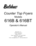
1
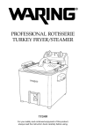
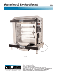
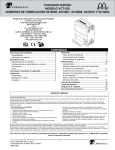
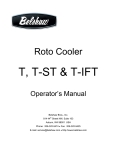
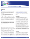
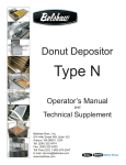
Thermoglaze
TG 50
Operator’s Manual
and
Technical Supplement
Belshaw Bros., Inc.
814 44th Street NW, Suite 103
Auburn, WA 98001 USA
Tel: (206) 322-5474
Fax: (206) 322-5425
Toll Free (US): 1-800-578-2547
E-mail: [email protected]
www.belshaw.com
Thermoglaze
TG 50
Operator’s Manual
Belshaw Bros., Inc.
814 44th Street NW, Suite 103
Auburn, WA 98001 USA
Phone: (206) 322-5474 • Fax: (206) 322-5425
Email: [email protected] • http://www.belshaw.com
Congratulations on buying a new
Thermoglaze from Belshaw Bros., Inc. Please
inspect the unit carefully for damage or
missing pieces immediately after receiving
your system. Belshaw cannot pay for shipping
damage, because the freight company has
accepted the machine from Belshaw in good
condition, and is responsible for its safe delivery.
For your protection, each crate should be
inspected before signing the Bill of Lading to
report any visible damage caused by the
trucker in transit, and account for the number
of crates.
EQUIPMENT RECORD
Please provide the information below when you correspond with us about your machine.
Purchased by _____________________________________________________________________
Installed by ______________________________________________________________________
Date of Installation ________________________________________________________________
Model number ___________________________________________________________________
Serial number
020708
MN-1717EN
Belshaw Bros., Inc.
814 44th Street NW, Suite 103
Auburn, WA 98001 USA
Phone: (206) 322-5474 • Fax: (206) 322-5425
Email: [email protected] • http://www.belshaw.com
Contents
1
Operation
1
2
Cleaning
3
Daily TG Cleaning Instructions
3
Belshaw Bros., Inc. • www.belshaw.com • Phone 206-322-5474 • Fax 206-322-5425
Thermoglaze 50 OM
MN-1717EN
iii
Preface
The operator of the Thermoglaze is expected to
behave safely, read this manual before operation,
and follow its instructions and warnings.
Study the instructions and warnings in this
manual carefully before operating the equipment.
A thorough understanding of how to install,
maintain, and safely operate the Thermoglaze
will prevent production delays and injuries. Prior
operation of the equipment before reading and
understanding the instructions in the manual will
void the warranties of the equipment.
To use the Thermoglaze safely, heed the
following warnings and all other warnings that
appear in this manual:
•
To avoid damaging the Thermoglaze,
never use force to assemble,
disassemble, operate, clean, or maintain
it.
Belshaw Bros., Inc. • www.belshaw.com • Phone 206-322-5474 • Fax 206-322-5425
iv
MN-1717EN
Thermoglaze 50 OM
1
Operation
•
Load glaze reservoir with 40 pounds (one
large bucket) of glaze and turn on the glaze
pump.
WARNING
DO NOT OPERATE GLAZER
WITHOUT GLAZE OR WATER IN THE
PUMP. DOING SO CAN CAUSE
PERMANENT DAMAGE TO THE PUMP
•
After the donuts have been in the
Thermolizer for at least 20 minutes (60
minutes for filled product), turn on glazer
using the on switch located on the main
control panel.
•
After the donuts are thawed, place a screen of
donuts from Thermolizer box to the infeed
end of the Thermoglaze conveyor and allow
the screen to travel through the oven and
glazer. This takes approximately 1-1/2 to 3
minutes.
•
When the screen of donuts is through the
glazer and stopped forward travel, place the
glazed product on a rack for cooling using
the 2 delrin tray grips provided with the unit.
Figure 1.1 – Control Panel View
•
Use main power switch to turn unit on and
off. Green power on button will illuminate
when power is on.
WARNING
E-STOP SHOULD BE RESERVED FOR
EMERGENCIES ONLY
•
Turn on oven power switch and heat for 30
minutes to allow it to reach operating
temperature.
o Heat light will go out when oven
reaches temperature.
WARNING
TO AVOID BURNING YOURSELF,
NEVER TOUCH THE THERMOGLAZE
UNIT, CONVEYOR, OR INTERIOR OF
THE OVEN WHILE THE MACHINE IS
IN USE
o Conveyor will not move until
oven is up to operating
temperature.
Belshaw Bros., Inc. • www.belshaw.com • Phone 206-322-5474 • Fax 206-322-5425
Thermoglaze 50 OM
MN-1717EN
1
WARNING
WARNING
THOROUGHLY CLEAN AND DRY THE
FLOOR IF WATER OR OTHER
MATERIALS ARE SPILLED. MATERIALS
SPILLED ON THE FLOOR MAY CAUSE
SERIOUS INJURY AND LOSS OF LIFE
SERIOUS PERSONAL INJURY MAY
FROM CONTACT WITH PINCH
POINTS BETWEEN CHAIN,
SPROCKETS AND PULLEY, CUTS OR
LOSS OF LIMB MAY OCCUR WHEN
CONTACTING THIS PINCH POINTS.
NEVER OPERATE THE MACHINE
WITH GUARDS AND COVERS
REMOVED.
WARNING
CONVEYOR WILL AUTOMATICALLY
START WHEN THERMOGLAZE
REACHES OPERATING
TEMPERATURE
CAUTION!
DONUT SCREENS ARE HOT AFTER
COMING OUT OF THE GLAZER AND
WILL BURN YOU IF YOU GRAB THEM
WITHOUT THE HANDLES
CAUTION!
TO AVOID BURNING YOURSELF,
NEVER TOUCH HOT INFEED OVEN
END PANEL WHEN MACHINE IS IN
OPERATION
CAUTION!
TO AVOID BURNING YOURSELF,
NEVER TOUCH HOT SCREEN WHEN
MACHINE IS IN OPERATION
CAUTION!
TO AVOID BURNING YOURSELF,
NEVER TOUCH HOT CONVEYOR
CHAIN WHEN MACHINE IS IN
OPERATION
CAUTION!
TO AVOID BURNING YOURSELF,
NEVER TOUCH HOT OUTFEED OVEN
END PANEL WHEN THERMOGLAZE
IS IN OPERATION
CAUTION!
SERIOUS PERSONAL INJURIES LIKE
SCRATCHES OR CUTS MAY RESULT
FROM CONTACT WITH SHARP
EDGES
CAUTION!
WARNING
LIFTING THE GLAZE BUCKET MAY
CAUSE SPRAINS OR BACK INJURY
REACHING ACROSS, LEANING OVER
THE MACHINE MAY RESULT IN BURN
WHEN MACHINE IS IN OPERATION
Belshaw Bros., Inc. • www.belshaw.com • Phone 206-322-5474 • Fax 206-322-5425
2
MN-1717EN
Thermoglaze 50 OM
2
Cleaning
Daily TG Cleaning
Instructions
Disassembly
1. Allow the Thermoglaze to completely
cool. (All material must under 130º)
2. Pump the unused glaze back into a bucket.
3. Lockout the TG at Circuit Breaker!
4. Remove the glaze trough.
7. Disconnect the conveyor drive coupling.
5. Remove the drive belt.
8. Remove the conveyor assembly through the
outfeed end of the oven.
6. Remove the glazer drain tray.
Belshaw Bros., Inc. • www.belshaw.com • Phone 206-322-5474 • Fax 206-322-5425
Thermoglaze 50 OM
MN-1717EN
3
9. Lift out drip tray.
12. Loosen the lower glaze hose clamp.
10.
13. Remove the lower glaze hose clamp and gasket.
Remove the oven crumb tray.
14. Remove the upper pump clamp.
11. Open the safety cover.
Belshaw Bros., Inc. • www.belshaw.com • Phone 206-322-5474 • Fax 206-322-5425
4
MN-1717EN
Thermoglaze 50 OM
15. Lift the glaze reservoir and remove the gasket
19. Remove the glaze pump cover and “O” ring.
16. Remove the glaze reservoir and hose.
20. Remove the glaze pump body.
17. Remove the drip pan.
18. Unscrew and remove the 4 glaze pump cover
wing nuts.
21. Insert a flat tip screw driver into the slot to
loosen the pump body if it can not be
removed by hand.
22. Remove the pump body and impellers.
Belshaw Bros., Inc. • www.belshaw.com • Phone 206-322-5474 • Fax 206-322-5425
Thermoglaze 50 OM
MN-1717EN
5
23. Remove the impellers from the pump body.
WARNING
SPILLED GLAZE ON FLOOR MAY
CAUSE SLIPPING AND FALLING,
RESULTING IN SPRAINS, BURNS,
BROKEN BONES OR BACK INJURY.
Belshaw Bros., Inc. • www.belshaw.com • Phone 206-322-5474 • Fax 206-322-5425
6
MN-1717EN
Thermoglaze 50 OM
Cleaning
1. Hand wash all parts of the oven and
glazer with warm soapy water.
2. Do not use caustic cleaners on oven parts.
3. You may use an approved oven cleaner
on the stainless steel finger cover only.
4. Do not use oven cleaner on any other part
of the oven or glazer!
5. Do not hose/spray down any part of this
machine.
6. Glaze pump body and parts.
CAUTION
FAILURE TO PROPERLY CLEAN OR
LUBRICATE GLAZE PUMP MAY
CAUSE DAMAGE TO THE PUMP GEAR
IMPELLERS.
Assembly
NOTE
LUBRICATE THE PUMP BODY, SHAFT
“O” RING, AND GEAR IMPELLERS
WITH “KAY” FOOD GRADE
LUBRICANT. SEE FOLLOWING
PICTURE.
NOTE
PUMP COVER CAN BE REMOVED
WITHOUT TOOLS
Belshaw Bros., Inc. • www.belshaw.com • Phone 206-322-5474 • Fax 206-322-5425
Thermoglaze 50 OM
MN-1717EN
7
WARNING
GROWTH OF ORGANISMS IN GAPS
CREVICESGLAZE PUMP, LINES AND
FRAME CAN RESULT FROM
IMPROPER CLEANING AND CAN
CAUSE MILD TO SERIOUS ILL
HEALTH
WARNING
DONUTS OR FILLING CATCH FIRE
DUE TO IMPROPER CLEANING CAN
CAUSE SERIOUS INJURY, BURNS OR
DEATH
Belshaw Bros., Inc. • www.belshaw.com • Phone 206-322-5474 • Fax 206-322-5425
8
MN-1717EN
Thermoglaze 50 OM
Assembly
1. Install the glaze pump body.
2. Install the drive gear impeller. Line up the flat
on the shaft with the flat in the impeller.
NOTE
4. Install the “O” ring into the glaze pump
cover. Make sure it stays in place and you
do not pinch it between the pump and
cover. The “O” ring may need to be
stretched before installing.
LUBRICATE THE PUMP BODY, SHAFT
“O” RING AND GEAR IMPELLERS
WITH FOOD GRADE MINERAL OIL.
5. Install the 4 wing nuts finger tight.
3. Install the lay gear impeller.
6. Set the upper gasket on top of the glaze
pump.
Belshaw Bros., Inc. • www.belshaw.com • Phone 206-322-5474 • Fax 206-322-5425
Thermoglaze 50 OM
MN-1717EN
9
7. Install glaze reservoir.
9. Install the drip pan.
8. Install the upper clamp.
10. Close the safety cover. Make sure key is
in safety switch
NOTE
THE GLAZE PUMP WILL NOT RUN
WITH THE SAFETY COVER OPEN
Belshaw Bros., Inc. • www.belshaw.com • Phone 206-322-5474 • Fax 206-322-5425
10
MN-1717EN
Thermoglaze 50 OM
11. Install the oven crumb tray.
12. Insert the conveyor through the outfeed
end of the oven.
14. Pull the drive coupling back and line it up
with the conveyor drive shaft.
15. Install the glaze drain tray.
16. Connect the drive belt.
CAUTION
CONVEYOR COUPLING MAY BE HOT
13. Make sure the locating pin is in the
matching hole.
Belshaw Bros., Inc. • www.belshaw.com • Phone 206-322-5474 • Fax 206-322-5425
Thermoglaze 50 OM
MN-1717EN
11
Thermoglaze
TG 50
Technical Supplement
Belshaw Bros., Inc.
814 44th Street NW, Suite 103
Auburn, WA 98001 USA
Phone: (206) 322-5474 • Fax: (206) 322-5425
Email: [email protected] • http://www.belshaw.com
Congratulations on buying a new
Thermoglaze from Belshaw Bros., Inc. Please
inspect the unit carefully for damage or
missing pieces immediately after receiving
your system. Belshaw cannot pay for shipping
damage, because the freight company has
accepted the machine from Belshaw in good
condition, and is responsible for its safe delivery.
For your protection, each crate should be
inspected before signing the Bill of Lading to
report any visible damage caused by the
trucker in transit, and account for the number
of crates.
EQUIPMENT RECORD
Please provide the information below when you correspond with us about your machine.
Purchased by _____________________________________________________________________
Installed by ______________________________________________________________________
Date of Installation ________________________________________________________________
Model number ___________________________________________________________________
Serial number
020708
MN-1718EN
Belshaw Bros., Inc.
814 44th Street NW, Suite 103
Auburn, WA 98001 USA
Phone: (206) 322-5474 • Fax: (206) 322-5425
Email: [email protected] • http://www.belshaw.com
Contents
1
Unloading and Uncrating
1
2
Installation
2
3
Assembly
3
4
Maintenance
6
5
Troubleshooting
7
SB-0345 Rev 1
SB-0315R3
6
12
18
Appendix
23
Belshaw Bros., Inc. • www.belshaw.com • Phone 206-322-5474 • Fax 206-322-5425
Thermoglaze 50 TS
MN-1718EN
iii
Preface
The operator of the Thermoglaze is expected to
behave safely, read this manual before operation,
and follow its instructions and warnings.
Study the instructions and warnings in this
manual carefully before operating the equipment.
A thorough understanding of how to install,
maintain, and safely operate the Thermoglaze
will prevent production delays and injuries. Prior
operation of the equipment before reading and
understanding the instructions in the manual will
void the warranties of the equipment.
To use the Thermoglaze safely, heed the
following warnings and all other warnings that
appear in this manual:
• To avoid damaging the Thermoglaze,
never use force to assemble,
disassemble, operate, clean, or maintain
it.
Belshaw Bros., Inc. • www.belshaw.com • Phone 206-322-5474 • Fax 206-322-5425
iv
MN-1718EN
Thermoglaze 50 TS
1
Unloading and Uncrating
DO NOT LIFT
EXCESSIVE WEIGHT
Once the crate has been delivered,
immediately take the covers off the crate and
inspect for hidden damage. If damage is
found, make a damage claim to the shipping
company. After inspection, cut the banding
and remove any other restrains from the
Thermoglaze unit. Remove the banding and
other packing material from the Thermolizer
unit. Roll the Thermolizer, carefully, off the
skid first and move it near the area where it
will be assembled.
.
Do not connect the Thermoglaze or the
Thermolizer to electrical power before
completing the assembly and placement of
the products.
Figure 1-1 shows the system in the crate ready to
be unpacked. The cartons under the Thermoglaze
contain the glaze trough. See Section 1 in
Operator’s Manual to assemble the unit. The
carton in the Thermolizer contains the doors and
other interior parts. See Thermolizer manual for
assembly instructions.
The Thermoglaze system has been designed for
quick assembly and installation. Within a short
time of receiving the system, the installer can
have the Thermoglaze ready to make donuts if
the electrical connections are properly installed
and inspected by the prevailing local authorities.
Figure 1-1 Packed Thermoglaze System
Belshaw Bros., Inc. • www.belshaw.com • Phone 206-322-5474 • Fax 206-322-5425
Thermoglaze 50 TS
MN-1718EN
1
2
Installation
Venting:
CAUTION
TO AVOID ELECTROCUTING
YOURSELF OR DAMAGING THE
THERMOGLAZE, NEVER ALLOW
WATER, STEAM, CLEANING
SOLUTION, OR OTHER LIQUID TO
ENTER THE ELECTRICAL PANELS OR
CONNECTIONS
Electrical:
Model
Dimensions
Power Requirements
TG50
88"L x 40W x
63"H
See data tag
Local codes prevail. The authorities having
jurisdiction are stated in NFPA 96-1994
regarding requirements for the Thermoglaze.
Building Layouts:
Specification sheets and AutoCAD drawings for
use in developing architectural drawings can be
provided by request. Please call your Belshaw
Bros., Inc. representative for help in defining
your requirements
Make sure that the power requirements of the
Thermoglaze, shown on the data plate, match
your power source.
Thermoglaze is provided with a 5-wire power
cord that must be connected to circuit protective
device in compliance with local, national and
municipal electrical and building codes. See data
plate voltage and current loads.
Do not apply electrical power to the system until
the assembly has been completed. See Section 1
in Operator’s Manual for the assembly of the
Thermoglaze.
Belshaw Bros., Inc. • www.belshaw.com • Phone 206-322-5474 • Fax 206-322-5425
2
MN-1718EN
Thermoglaze 50 TS
3
Assembly
Clean all parts with mild soap and water and
let dry before assembly and applying
electrical power to the equipment.
The Thermoglaze unit is design for ease of
assembly and use. The system is crated in a
manner so there are few pieces to put together
once the Thermoglaze is in place for production.
After unpacking the system per the uncrating
instructions, 1 item needs to be placed on the
Thermoglaze to finish assembly: the glaze
trough. The Glaze trough slips into the 2 holes on
either side of the drain tray with the waterfall
headed toward the oven. See figure 3-1 and 3-4
for help setting the trough in place. After the
trough is in place attach the glaze hose to the
trough by pushing it in the hose mount in the
center of the trough.
To help familiarize you with your Thermoglaze,
please study the following photographs:
Figure 3-1 Thermoglaze front view
Belshaw Bros., Inc. • www.belshaw.com • Phone 206-322-5474 • Fax 206-322-5425
Thermoglaze 50 TS
MN-1718EN
3
Main Control Panel
Glaze Trough
Glaze Hose
Transfer Shaft
Drain Tray
Service Kit
Tray Grips
Figure 3-2 Right Hand View
Figure 3-3 Control Panel View
WARNING
TURN OFF POWER SOURCE TO THE
MACHINE BEFORE REMOVING ANY
ACCESS COVER OR GUARDS
Belshaw Bros., Inc. • www.belshaw.com • Phone 206-322-5474 • Fax 206-322-5425
4
MN-1718EN
Thermoglaze 50 TS
The Thermoglaze system consists of a Thermoglaze
unit and the Thermolizer. They are placed in unison
in the area located for the production of donuts. See
Figure 3-4 for Thermoglaze system.
Figure 3-4 Thermoglaze System.
WARNING
DO NOT CONNECT THE
THERMOGLAZE TO ELECTRICAL
POWER BEFORE COMPLETING THE
ASSEMBLY PLACEMENT OF
PRODUCTS
Belshaw Bros., Inc. • www.belshaw.com • Phone 206-322-5474 • Fax 206-322-5425
Thermoglaze 50 TS
MN-1718EN
5
4
Maintenance
The ThermoGlaze is engineered to need little
maintenance. By keeping the system clean, the
equipment will last for years. The only
maintenance that is required is the following:
When cleaning the donut system, check all
rubber gaskets for wear and replace when
necessary. Check for wear on impellers of the
glaze pump, replace when necessary. .
WARNING
ELECTRICAL FIRES CAN CAUSE
SERIOUS SHOCK, INJURY, BURNS OR
DEATH. ALWAYS DISCONNECT
MACHINE FROM POWER SOURCE
BEFORE MAINTENANCE
DO NOT spray machine with water or cleaning
agents to clean. Only wipe main unit off with
damp cloth.
WARNING
HAZARDOUS VOLTAGE
CONTACT WITH ELECTRICITY IN
CONTROL BOX CAN CAUSE SHOCKS,
BURNS OR DEATH. ALWAYS
DISCONNECT THE CONTROL BOX
FROM POWER SOURCE BEFORE
MAINTENANCE
WARNING
CONTACT WITH ELECTRICITY IN
MAIN CABLE CAN CAUSE SHOCKS,
BURNS OR DEATH ALWAYS
DISCONNECT MAIN ELECTRICAL
CABLE THE POWER SOURCE BEFORE
MAINTENANCE
Belshaw Bros., Inc. • www.belshaw.com • Phone 206-322-5474 • Fax 206-322-5425
6
MN-1718EN
Thermoglaze 50 TS
5
Troubleshooting
Call Belshaw Bros. at (206)322-5474, or (800)
578-2547. One of our customer support
representatives will be happy to help you. When
you call, please specify the following:
•
The model name of the machine.
•
The serial number of the machine.
•
The voltage, phase, and hertz (cycle) of
the machine. This information can be
found on the small, rectangular data
tag/plate.
Following is a troubleshooting chart to help you
identify and solve some basic problems.
WARNING
DISCONNECT THE MACHINE FROM
THE POWER SOURCE BEFORE
DISASSEMBLING, REPAIRING, OR
WIRING.
WARNING
CAUTION
IF YOU PERFORM REPAIRS
YOURSELF OR HAVE THEM
PERFORMED BY ANYONE OTHER
THAN BELSHAW BROS. OR A
SERVICE TECHNICIAN AUTHORIZED
BY BELSHAW BROS., YOU DO SO AT
YOUR OWN RISK.
TO AVOID SERIOUS INJURY ALWAYS
DISCONNECT THE THERMOGLAZE
FROM THE POWER SOURCE BEFORE
TROUBLESHOOTING
Belshaw Bros., Inc. • www.belshaw.com • Phone 206-322-5474 • Fax 206-322-5425
Thermoglaze 50 TS
MN-1718EN
7
CONVEYOR WILL NOT MOVE
Possible Causes
What To Do
Oven not to correct temperature yet.
Wait until the oven comes to temp.and the ready
light comes on.
Conveyor is jammed.
Check for obstruction in conveyor and remove.
Motor circuit breaker is tripped.
Push the black circuit breaker reset at bottom of
oven control panel.
GLAZER WILL NOT PUMP GLAZE
Glazer motor is not running.
Check to make sure the motor is running.
(See Pump Motor Will Not Run)
Glazer pump impellers are worn.
1. Disconnect power.
2. Replace impellers.
The rear panel safety key is not inserted in the
safety switch.
Make sure the rear panel safety key is inserted into
the safety switch.
GLAZE IS MISSING THE DONUTS ON ONE SIDE OF THE GLAZE SCREEN
Glazer or glaze trough is not level.
Adjust level of glaze trough by moving set collar.
Glaze pump is running too slow.
1.
2.
3.
4.
Disconnect from power.
Open Electrical Enclosure.
Turn glazer speed control clockwise.
Close Electrical Enclosure.
Belshaw Bros., Inc. • www.belshaw.com • Phone 206-322-5474 • Fax 206-322-5425
8
MN-1718EN
Thermoglaze 50 TS
THE PUMP MOTOR WILL NOT RUN
Possible Causes
What To Do
The connection of the power cord to the power
source is faulty.
Make sure the power cord is properly connected
into a proper power source.
The circuit breaker has been tripped.
1.
2.
3.
4.
The rear panel is not installed properly
1. Reinstall the rear panel.
2. Make sure that the key attached to the rear
panel is inserted into the safety interlock
switch.
Disconnect from power.
Open electrical enclosure.
Reset circuit breaker.
Close electrical enclosure.
NOTE
The glaze pump will not run with the rear
panel removed.
THE FILL HOSE IS LEAKING
Possible Causes
What To Do
Fill hose is leaking at the connection.
Hose bracket needs adjusting or tightening.
Fill hose is leaking near the pump.
Check for missing or damaged o-ring.
Belshaw Bros., Inc. • www.belshaw.com • Phone 206-322-5474 • Fax 206-322-5425
Thermoglaze 50 TS
MN-1718EN
9
Calibration Procedure for Temperature and Cook Time on
the Thermoglaze Model TG50
Turn off power to the TG50 before removing any
access covers. This procedure should be
performed only by qualified service technicians.
Remove the electrical box cover on the oven to
access the temperature and speed control
adjustment potentiometers. The following is a
photo of the location of the adjustment
potentiometers for the temperature and cooking
time for the Belshaw TG50 Thermoglaze.
Rocker Switches
Temperature Controller
Speed Controller
Conveyor drive motor
Transformer
MCR
Safety Switch
Terminal Block
Power Distribution Block
Heater Contactor
SSR Relays
Timer
VFD
Circuit Breakers
Glaze Pump
Belshaw Bros., Inc. • www.belshaw.com • Phone 206-322-5474 • Fax 206-322-5425
10
MN-1718EN
Thermoglaze 50 TS
Speed control/cook time adjustment:
Turn on the oven and allow it to heat for 30 minutes.
Put a glaze screen on the conveyor chains that run through the oven. With the oven in operation, time the
leading edge of the screen as it enters the oven until the leading edge just leaves the exit end of the oven.
Adjust the potentiometer until the desired time/speed is found. To increase the cook time, turn the
potentiometer clockwise. To decrease the cook time, turn the potentiometer counterclockwise. The factory
setting for cook time for the TG50 is 1 ½ minutes.
Temperature Adjustment:
Measure the temperature from the lower baffle on the exit end of the oven. Place a thermocouple in the
hole located on the baffle, 3rd row from the outside, 3rd hole from the back side of the oven. Note: The
back side of the oven has a fan motor extended from it. Adjust the temperature by rotating the
potentiometer located to the right of the speed control, clockwise increases the temperature, and
counterclockwise decreases the temperature. The factory setting is 400º F.
NOTE
PUMP COVER CAN BE REMOVED
WITHOUT TOOLS.
Belshaw Bros., Inc. • www.belshaw.com • Phone 206-322-5474 • Fax 206-322-5425
Thermoglaze 50 TS
MN-1718EN
11
SB-0345 Rev 1
AFFECTS: TG-50
PURPOSE: PROGRAMMING THE OGDEN ETR-9000 TEMPERATURE CONTROLLER
Operator Interface:
The operator interface on the Ogden ETR-9000, Temperature Controller, consists of the following:
•
A scroll key
•
Up
•
A reset key
used to select a parameter to be viewed or adjusted.
and down
arrow keys are used to increase or decrease the selected parameter.
used to return to normal operation mode.
Figure 1.2 – Operator Interface Description
Menu Overview:
There are three main menus that contain parameters that require programming; they are User Menu,
Setup Menu, and Calibration Mode. The figure below (Figure 2) shows the sequence of operations
necessary to access the programming parameters in each menu.
Belshaw Bros., Inc. • www.belshaw.com • Phone 206-322-5474 • Fax 206-322-5425
12
MN-1718EN
Thermoglaze 50 TS
Figure 1.3 - Menu Flow Chart
Belshaw Bros., Inc. • www.belshaw.com • Phone 206-322-5474 • Fax 206-322-5425
Thermoglaze 50 TS
MN-1718EN
13
TG-50 Parameter Settings
Tables 1, 2 and 3 below list of the temperature controller default settings and the Belshaw Factory
settings. When installing a new controller 3 of the default setting must be changed to the Belshaw
Factory settings.
•
Push and hold the scroll key
•
Push the scroll key
•
Push the Up
for 3 seconds, this will take you to the “SEt” menu.
once to access the “LocK” parameter.
or down
arrow keys to change “LocK” to “nonE”.
•
to page through the settings and the Up
or down
arrow keys to
Push the scroll key
change the settings listed in the Belshaw “Factory” column. (see tables 1, 2 and 3)
When finished setting parameters.
•
Continue pushing the scroll key
•
Push the Up
•
Push the reset key
or down
until you are back to “LocK”.
arrow keys to set “LocK” to “uSEr”.
to return normal operation.
Default Settings:
In the event that parameters have been modified without recording the modifications, change each
parameter to match those listed in Tables 1, 2 and 3 listed below (controller parameter default settings).
Then adjust SP1H, PB, OUT2 and the LocK parameters as listed in Belshaw “Factory” below. Then set
SP1 to 420ºF.
Belshaw Bros., Inc. • www.belshaw.com • Phone 206-322-5474 • Fax 206-322-5425
14
MN-1718EN
Thermoglaze 50 TS
Table 1 - Parameter Descriptions
Factory
420ºF
set to
“uSEr”
after
setup
450ºF
-40ºF
0ºF
0ºF
Belshaw Bros., Inc. • www.belshaw.com • Phone 206-322-5474 • Fax 206-322-5425
Thermoglaze 50 TS
MN-1718EN
15
Table 2 - Parameter Descriptions
Set to
“nonE”
Belshaw Bros., Inc. • www.belshaw.com • Phone 206-322-5474 • Fax 206-322-5425
16
MN-1718EN
Thermoglaze 50 TS
Table 3 - Parameter Descriptions
Set to
Belshaw Bros., Inc. • www.belshaw.com • Phone 206-322-5474 • Fax 206-322-5425
Thermoglaze 50 TS
MN-1718EN
17
SB-0315R3
AFFECTS:
TG-50, TG-25
PURPOSE:
REVISED: 5/10/2006 JD
VFD-0017-3 PROGRAMMING INSTRUCTIONS
ENTER BUTTON
DISPLAY
ESC
SCROLL UP/SCROLL
DOWN
Figure 1
Figure 2
Belshaw Bros., Inc. • www.belshaw.com • Phone 206-322-5474 • Fax 206-322-5425
18
MN-1718EN
Thermoglaze 50 TS
General:
Figure 1, above, shows the location of programming/navigating buttons on the face of the Altivar 11
(Belshaw P/N: VFD-0017). Figure 2 shows the navigation paths to various programming parameters.
The following has been adapted from the ATV11 Technical Manual which can be found at
http://ecatalog.squared.com/pubs/Motor%20Control/AC%20Drives/Altivar%2011/VVDED302026US.pdf
Programming:
Using Figures 1, and 2 navigate to the following programming parameters and set them as shown below
in Table 1. Items listed as default are set at the factory and should be verified.
The parameters in unshaded boxes can only be modified when the controller is stopped.
Remove jumper wire from terminal 15 to stop drive.
The parameters in shaded boxes can be modified with the controller operating or stopped.
MENU
PARAMETER
1st Level
ACC
SECONDARY
PARAMETER
dEC
LSP
HSP
ItH
FUn
SETTING
Acceleration ramp time
(sec.)
Deceleration ramp time
(sec.)
Low Speed (hz)
High Speed (hz)
3 (default)
UnS
Motor thermal current
(amps)
Configuration of Analog
Input
Motor voltage (volts)
FrS
Motor frequency (hz)
nCr
Motor current (amps)
COS
Motor power factor
Alt
drC
FUNCTION
tCC
rrS
PS2
PI
rSF
bFr
ACt
tCt
L1A
L1b
PIF
2-wire control
Type of 2-wire control
Reverse operation
Assignment of L1A
Assignment of L1B
Assignment of PI
function feedback
Fault reset
Motor Frequency (hz)
3 (default)
0 (default)
50/60 (default) based on motor
Hz
2.1
(Set to motor nameplate amps)
5U (default)
230
(Set to motor nameplate
voltage)
60
(Set to motor nameplate
frequency)
2.1
(Set to motor nameplate
current)
.80
(Set to motor nameplate power
factor (sometimes labeled ‘pf’))
2c (default)
LEL
nO
nO
nO
nO (default)
nO (default)
60 for domestic machines
(default).
50 for AS/NZ, and CE
machines;
Belshaw Bros., Inc. • www.belshaw.com • Phone 206-322-5474 • Fax 206-322-5425
Thermoglaze 50 TS
MN-1718EN
19
Returning VFD to factory default settings:
Sometimes the easiest way to ensure that the VFD has the correct operating parameters is to
return the configuration parameters to factory default and re-enter the few parameters changed
for use with the TG-25 and the TG-50s. There are currently over 50 adjustable parameters
available with this VFD of which 11 need to be changed from factory default
To reset the VFD to operate on the TGs, reset the parameters to the factory default as shown
below and re-enter and/or verify the parameters in the programming section above.
MENU
PARAMETER
FUn
FCS
SECONDARY
PARAMETER
FUNCTION
SETTING
Reset
configuration to
factory default
Lnl (Must hold ENT
key for 2 sec)
ONLY USE THIS
PARAMETER TO
RETURN VFD TO
FACTOR DEFAULT
CONFIGURATION.
IF
Note The drive must be stopped to modify this parameter. Remove jumper wire from terminal 15 to
stop drive
FAULTS – CAUSES – REMEDIES
Clearing the fault:
Cut the power supply to the drive in the event of a non-resettable fault.
Wait for the display to go off completely.
Find the cause of the fault in order to correct it.
Restore the power supply – this clears the fault if it has disappeared.
Drive does not start, no fault displayed:
Check that the run command input has been jumpered (Jumper is required between terminals
LI1 and +15V).
When the drive is switched on, or at a manual fault reset, or after a stop command, the motor
can only be supplied with power once the ”forward” commands have been reset. Otherwise, the
drive will display “rdy” or “nSt” but will not start.
Belshaw Bros., Inc. • www.belshaw.com • Phone 206-322-5474 • Fax 206-322-5425
20
MN-1718EN
Thermoglaze 50 TS
Drive does not start, display off:
Check that line voltage is present at the drive terminals
Unplug all the connections on the drive U, V, W terminals and check that there is no short circuit
between the phase and earth in the motor wiring or in the motor.
Faults which cannot be reset automatically:
The cause of the fault must be removed before resetting by switching power off and on again.
FAULT
CFF
PROBABLE CAUSE
•
•
Return to factory settings and re-enter
parameters
•
The current
configuration is
inconsistent
Load relay control fault
or charging resistor
damaged
•
Replace the drive
•
Internal fault
•
Check the environment
(electromagnetic compatibility)
Replace drive
Check the settings
Check the size of the motor/drive/load
Check the state of the mechanism
Check the cables connecting the drive
to the motor, and the motor insulation
Configuration fault
CrF
Capacitor charging
circuit
InF
REMEDY
Internal fault
OCF
Overcurrent
SCF
•
•
•
•
Motor short-circuit
SOF
Overspeed
•
Ramp to short
Inertia or load too high
Mechanical locking
Insulation fault or shortcircuit at the drive
output
Instability or driving load
too high
•
•
•
•
•
•
•
•
Check the motor, gain and stability
parameters
Add a breaking resistor and module
Check the size of the motor/drive/load
Belshaw Bros., Inc. • www.belshaw.com • Phone 206-322-5474 • Fax 206-322-5425
Thermoglaze 50 TS
MN-1718EN
21
Faults which can be reset with automatic restart function, after the cause of the fault disappeared:
These faults can also be reset by switching the drive off and on again.
FAULT
ObF
PROBABLE CAUSE
•
Overvoltage during
deceleration
Braking too sudden or
driving load
REMEDY
•
•
•
•
Drive temperature too
high
•
•
Trigger by motor current
too high
•
Line voltage too high
Disturbed line supply
•
Overvoltage
•
•
PHF
•
Dive incorrectly
supplied of blown circuit
protection
Failure of one phase
•
OHF
Drive over
temperature
OLF
Motor overload
OSF
Line phase failure
•
•
Increase the deceleration time
Install a braking module and a braking
resistor if necessary
Activate the brA function if it is
compatible with the application
Sheck the motor load, the drive
ventilation and the environment. Wait
for the drive to cool down before
restarting
Check the setting of the motor thermal
protection, check the motor load. Wait
for the motor to cool down before
restarting
Check the line voltage. The
overvoltage threshold is 415VDC on
the DC bus
Check the power connections and the
circuit protection
Reset
Faults which can be reset as soon as its cause disappears:
FAULT
USF
Undervoltage
PROBABLE CAUSE
•
•
•
Line supply too low
Transient voltage dip
Damaged load resistor
REMEDY
•
•
Check the voltage and the voltage
parameter. The undervoltage
threshold is 230vDC on the DC bus
Replace the drive
Belshaw Bros., Inc. • www.belshaw.com • Phone 206-322-5474 • Fax 206-322-5425
22
MN-1718EN
Thermoglaze 50 TS
6
Appendix
See Parts List Drawing Insert Page.
Belshaw Bros., Inc. • www.belshaw.com • Phone 206-322-5474 • Fax 206-322-5425
Thermoglaze 50 TS
MN-1718EN
23