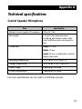
1
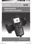
SAILOR 6204/6205 Control
Speaker Microphone
User manual
SAILOR 6204/6205 Control Speaker Microphone
Document number: 98-133300-C
Release date: 22 October 2013
Copyright: © 2013 Thrane & Thrane A/S. All rights reserved.
Trademark Acknowledgements
• Thrane & Thrane is a registered trademark of Thrane & Thrane A/S in the
European Union and the United States.
• SAILOR is a registered trademark of Thrane & Thrane A/S.
• Other product and company names mentioned in this manual may be
trademarks or trade names of their respective owners.
Disclaimer
Any responsibility or liability for loss or damage in connection with the use of this
product and the accompanying documentation is disclaimed by Thrane & Thrane
A/S. The information in this manual is provided for information purposes only, is
subject to change without notice and may contain errors or inaccuracies. Manuals
issued by Thrane & Thrane A/S are periodically revised and updated. Anyone
relying on this information should acquire the most current version e.g. from
www.cobham.com/satcom or from the distributor. Thrane & Thrane A/S is not
responsible for the content or accuracy of any translations or reproductions, in
whole or in part, of this manual from any other source.
Thrane & Thrane A/S is trading as Cobham SATCOM.
i
Safety warning
The following general safety precautions must be observed during all
phases of operation, service and repair of this equipment. Failure to
comply with these precautions or with specific warnings elsewhere in
this manual violates safety standards of design, manufacture and
intended use of the equipment. Thrane & Thrane assumes no liability for
the customer's failure to comply with these requirements.
Warranty limitation
IMPORTANT - The radio is a sealed waterproof unit (classified IPX8). To
create and maintain its waterproof integrity it was assembled in a
controlled environment using special equipment. The radio is not a user
maintainable unit, and under no circumstances should the unit be
opened except by authorized personnel. Unauthorized opening of the
unit will invalidate the warranty.
Installation and service
Installation and general service must be done by skilled service
personnel.
ii
Emergency call for SAILOR 6204
Make sure your VHF Radio is on CH16
Press
Use the CONTROL SPEAKER
MICROPHONE for voice calling
MAYDAY-MAYDAY-MAYDAY
OWN ID
This is
NAME-NAME-NAME
CALLSIGN
or other IDENTIFICATION
SHIP‘s NAME:
CALLSIGN:
MAYDAY
NAME of the VESSEL in distress
CALLSIGN or other IDENTIFICATION
POSITION
given as latitude and longitude
or
If latitude and longitude are not known
or if time is insufficient,
in relation to a known geographical location
NATURE of distress
Kind of ASSISTANCE required
Any other useful INFORMATION
99-133823
iii
Emergency call with Distress button for SAILOR 6205
Lift Cover
Press RED Button
until beep sounds continuously
(more than 3 seconds)
Press
Use the CONTROL SPEAKER
MICROPHONE for voice calling
Make sure your VHF radio is on CH16
MAYDAY-MAYDAY-MAYDAY
OWN ID
This is
NAME-NAME-NAME
CALLSIGN
SHIP‘s NAME:
CALLSIGN:
or other IDENTIFICATION
MMSI
(If the initial alert is sent by DSC)
MAYDAY
NAME of the VESSEL in distress
CALLSIGN or other IDENTIFICATION
MMSI
(If the initial alert is sent by DSC)
POSITION
given as latitude and longitude
or
If latitude and longitude are not known
or if time is insufficient,
in relation to a known geographical location
NATURE of distress
Kind of ASSISTANCE required
Any other useful INFORMATION
99 133825
MMSI:
Manual Overview
This manual has the following chapters:
•
Introduction contains a description of the Control Speaker
Microphone.
•
Operation explains how to work with the Control Speaker Microphone.
•
Installation has dimensional drawings and other information useful
when unpacking and installing the unit.
•
Service and maintenance contains support and warranty information.
Related documents
Title and description
Document number
SAILOR 6222 VHF DSC User manual
98-131184
SAILOR 6248 VHF User manual
98-131186
SAILOR 6249 VHF Survival Craft User manual
98-133865
SAILOR 6000 VHF Program Installation manual
98-135548
v
Table of contents
Chapter 1 Introduction
Overview ............................................................................ 1
Controls ..............................................................................2
Display overview .................................................................3
Chapter 2 Operation
Power on and general navigation ....................................... 5
Button functions .................................................................6
Sending a Distress message (SAILOR 6205) ........................7
Chapter 3 Installation
Unpacking ..........................................................................9
Initial inspection .................................................................9
What’s in the box ...............................................................9
Installing the Control Speaker Microphone ....................... 10
Dimensional drawing, with cradle .................................... 10
Drilling plan ...................................................................... 11
Connector ..........................................................................12
Chapter 4 Service and maintenance
Contact for support ............................................................13
Preventive maintenance ....................................................13
Warranty and returning units for repair ............................13
Repacking for shipment .....................................................14
App. A
Technical specifications
Control Speaker Microphone ............................................ 15
Index ....................................................................................................17
vii
viii
Chapter 1
Introduction
Overview
The SAILOR 6204/05 Control
Speaker Microphone (CSM) is a
control and speaking device for
remote radio operation of a VHF
radio. The SAILOR 6204/6205 is
powered by the radio and has
full VHF radio functionality. The
SAILOR 6205 has additionally
class D DSC functionality.
CSM type
MED
SAILOR 6204
R&TTE
SAILOR 6205
The Control Speaker
Microphone is waterproof to the
IPx8 and IPx6 standard.
The Control Speaker Microphone has a display with a view area of
40x30 mm and a menu-driven setup. The display can be dimmed for
optimum readability and visibility (both day and night). Use the selector
wheel and buttons to access the desired radio functions.
Up to four Control Speaker Microphones can be connected to one radio.
If the radio requires the audio, the microphone of the Control Speaker
Microphone is automatically switched off.
1
Introduction
Controls
1.
On/off and volume.
1
2. Dim display (short press),
keyboard lock (long press).
3. Soft keys for radio operation.
2
4. Push To Talk button (PTT) to
activate transmit mode.
3
4
5
6
7
5. Selector wheel to select a
channel or soft key.
6. Shift key to switch between
channel and soft key
selection.
7.
SCAN
HI/LO
LOCAL
Replay button to play back
recorded voice messages.
8. Squelch control to mute
background noise.
9. 16/C quick selection key for
channel 16 and the
programmed call channel.
10. Only SAILOR 6205: Distress button on the rear.
2
16
DISTRESS/CALL
INT
WATCH
8
9
10
Introduction
Display overview
The picture shows the display Example for SAILOR 6204 and VHF radio
after start-up. The display holds
2
various fields of information of
1
the VHF radio, depending on
3
the currently selected function.
SCAN
1.
Soft-key functions of the
radio.
2. Current working channel of
the radio.
HI/LO
LOCAL
16
DISTRESS/CALL
INT
4
WATCH
3. Service line containing
temporary information
relevant for the current
channel or function.
4. Channel properties next to the currently selected VHF channel (if any)
and current state of the radio (RX or TX).
Only SAILOR 6205: The position and MMSI number for the connected
radio is shown in the DSC window (the lower half of the radio’s display)
in stand-by mode.
For a detailed description of each function available see the user manual
of the radio.
3
Introduction
4
Chapter 2
Operation
Note
Before using the Control Speaker Microphone make sure it is
correctly connected to the radio at the connector marked CTRL
at the back of the radio or via a connection box. See the radio’s
installation manual for further information.
Power on and general navigation
1.
To power on, press the knob at the
top. The display lights up and shows
the current display of the radio.
To power off, press down the knob at
the top and follow the instructions
given in the display.
2. To transmit, press the PTT button on 2
the left side of the Control Speaker
Microphone.
1
3
SCAN
HI/LO
LOCAL
16
DISTRESS/CALL
INT
WATCH
3. To adjust the speaker volume turn the 4
knob at the top.
4. To change the working channel or
select a soft key function (Shift), turn
the selector wheel. The soft key
functions depend on the radio to
which the Control Speaker
Microphone is connected.
See the radio’s user manual for further
information.
5
Operation
When operating the Control Speaker
Microphone, the radio is occupied.
When operating the radio, the Control
Speaker Microphone is occupied. On
the radio you can override the state of
being occupied by pressing any key or
lifting the handset.
Button functions
To dim the display backlight, make a short press on the Dim/lock button
on the left side of the Control Speaker Microphone.
To lock/unlock the keys, make a long press on the Dim/lock button on the
left side of the Control Speaker Microphone. To unlock the keys, repeat
the key press.
Button
Function
To switch between channel and soft key selection.
To replay messages recorded by the radio.
To adjust squelch. Adjust the squelch level by turning
the selector wheel. Press the key SQ again or wait for
time-out to return to normal operation.
A single, short press on the 16/C key always
brings you to channel 16, the international calling and
Distress channel, no matter what state the Control
Speaker Microphone or the radio is in.
6
Operation
Sending a Distress message (SAILOR 6205)
1.
Lift the cover of the red Distress button at the rear of the
SAILOR 6205 and press and hold the distress button for
longer than 3 seconds. For short step-by-step
instructions how to proceed when sending a distress
message see Emergency call with Distress button for
SAILOR 6205 on page iv.
When the distress signal is sent, CH70
and Tx appear in the display. A twoseconds steady tone is heard from the
radio.
2. The radio watches for a DSC
acknowledgement transmission on
channel 70.
3. To pause the automatic resend procedure press the shift key, turn the
selector wheel and press OK on PAUSE.
4. To annul the distress message press the soft key ANNUL. For further
details see the user manual of the connected radio.
5. When a distress acknowledgement is received, a pop-up window is
displayed. Start distress communication on channel 16 to inform
about your distress situation.
Note
If no distress acknowledgement is received within a period of
3,5 to 4,5 minutes, the distress message will automatically be
retransmitted.
7
Operation
Having pressed the red distress button and sent the distress message, the
following information is displayed:
•
STATION: shows the radio’s MMSI number.
•
NAT: shows the nature of distress.
•
LAT:, LON:, POS UTC: shows the distress position data as transmitted.
•
MODE: shows the communication mode.
•
Elapsed time after initiation of own distress.
•
Time to next repeat of sending own distress.
If you sent a distress message, the VHF radio is automatically set to
channel 16, the channel reserved for international distress, safety and
calling.
See the radio’s user manual for further details.
8
Chapter 3
Installation
Unpacking
Initial inspection
Inspect the shipping carton immediately upon receipt for evidence of
damage during transport. If the shipping carton is severely damaged or
water stained, request that the carrier's agent be present when opening
the carton. Save the carton packing material for future use.
To avoid electric shock, do not apply power to the system if
there is any sign of shipping damage to any part of the front
or rear panel or the outer cover. Read the safety summary at
the front of this manual before installing or operating the
system.
After unpacking the system, inspect it thoroughly for hidden damage
and loose components or fittings. If the contents are incomplete, if there
is mechanical damage or defect, or if the system does not work properly,
notify your dealer.
What’s in the box
•
Control Speaker Microphone with spiral cable and connector
•
Cradle for Control Speaker Microphone
•
User manual (this manual)
•
5 m extension cable with connector
•
Kit with mounting screws
9
Installation
Installing the Control Speaker Microphone
Dimensional drawing, with cradle
10
Installation
Drilling plan
11
Installation
Connector
Connector type: Circular connector, 12 pin.
Pin assignment: Connector front view on the VHF
radio:
1
2
11
3
Description
7
12
10
4
Pin
8
9
6
5
Wire color
1
GND for cable screen
Brown
2
Internal GND=- Battery
Blue
3
Battery supply when radio is on
White
4
Battery supply when radio is on
Green
5
CAN+
Yellow
6
CAN-
Grey
7
Internal GND = - Battery
Pink
8
On/off from Control Speaker
Microphone
Red
9
RX out +
Black
10
RX out -
Orange
11
TX in +
Violet
12
TX in -
Cyan
Connecting several Control Speaker Microphones
For instructions how to connect several Control Speaker Microphones
see the system configuration examples in the radio’s installation
manual.
12
Chapter 4
Service and maintenance
Contact for support
Contact your authorized dealer for technical service and support of the
Control Speaker Microphone.
Preventive maintenance
Maintenance of the Control Speaker Microphone can be reduced to a
maintenance check at each visit of the service staff. Inspect it for
mechanical damages, salt deposits, corrosion and any foreign material.
Due to its robust construction and ruggedness the Control Speaker
Microphone has a long lifetime. Anyway it must carefully be checked at
intervals not longer than 12 months - dependent on the current working
conditions.
Warranty and returning units for repair
Should your Cobham SATCOM product fail, please contact your dealer or
installer, or the nearest Cobham SATCOM partner. You will find the
partner details on www.cobham.com/satcom where you also find the
Cobham SATCOM Self Service Center web-portal, which may help you
solve the problem.
Your dealer, installer or Cobham SATCOM partner will assist you
whether the need is user training, technical support, arranging on-site
repair or sending the product for repair.
Your dealer, installer or Cobham SATCOM partner will also take care of
any warranty issue.
13
Service and maintenance
Repacking for shipment
Should you need to send the product for repair, please read the below
information before packing the product.
The shipping carton has been carefully designed to protect the Control
Speaker Microphone and its accessories during shipment. This carton
and its associated packing material should be used when repacking for
shipment. Attach a tag indicating the type of service required, return
address, part number and full serial number. Mark the carton FRAGILE
to ensure careful handling.
Note
Correct shipment is the customer’s own responsibility.
If the original shipping carton is not available, the following general
instructions should be used for repacking with commercially available
material.
1.
Wrap the defective unit in heavy paper or plastic. Attach a tag
indicating the type of service required, return address, part number
and full serial number.
2. Use a strong shipping container, e.g. a double walled carton.
3. Protect the front- and rear panel with cardboard and insert a layer of
shock-absorbing material between all surfaces of the equipment and
the sides of the container.
4. Seal the shipping container securely.
5. Mark the shipping container FRAGILE to ensure careful handling.
Failure to do so may invalidate the warranty.
14
Appendix A
Technical specifications
Control Speaker Microphone
Item
Specification
Weight Control Speaker Microphone
320 g (0.7 lbs)
Box weight
1.2 kg (2.6 lbs) approximately,
including wall mount cradle, cable
and Installation and user manual in
box.
Dimensions
Height: 173 mm
Width: 70 mm
Depth: 52 mm, including front selector
wheel and cradle
Operating temperature
-25°C to 55°C (5°F to 131°F)
Storage temperature
-30°C to 80°C (-22°F to 176°F)
Power supply
Powered by the radio.
Current consumption
Powered by the radio.
For more specifications see the radio’s installation manual.
15
Technical specifications
16
Index
Numerics
16/C, 2, 6
E
A
emergency call procedure, iii
DSC, iv
extension cable, 9
accessories included, 9
approvals, 1
I
installation, 9
C
connect
several CSMs, 12
connector
CTRL, 12
pin assignment, 12
contact, 13
CTRL connector, 12
K
D
lock, 6
key
16/C, 6
replay, 6
Shift, 6
squelch, 6
L
delivery, items included, 9
dim, 2, 6
dimensions, 10
Distress
button, 7
channel, 6
display, 8
time since activation, 8
Distress message
send, 7
drilling plan, 11
M
mounting screws, 11
P
pin assignment, 12
power
off, 5
on, 5
PTT, 2
17
R
repacking for shipment, 14
replay, 2, 6
S
safety warning, ii
salt deposits, 13
screws, 11
Shift key, 6
soft key
function, 5
selection, 6
speaker volume, 5
specifications, 15
squelch, 2
key, 6
support, 13
T
technical data, 15
temperature
operational, 15
storage, 15
U
unlock, 6
W
warranty, 13
weight, 15
98-133300-C
www.cobham.com/satcom