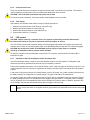
1
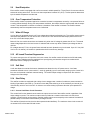
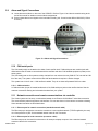
CXDM-E1 DC
input bus bar (hot)
(hot)
CXDM-E1 DC
return bus bar
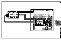
Figure 11–Battery / rectifier bus bar connections
5.8
Distribution Cabling
5.8.1
Calculating Output Wire Size Requirements
Wire size is calculated by first determining the appropriate maximum voltage drop requirement. Using the formula
below calculate the CMA wire size requirement. Determine the size and number of conductors required to satisfy
the CMA requirement.
CMA = (A x LF x K) / AVD, where:
CMA = Cross section of wire in circular mil area
A = Ultimate drain in amps
LF = Conductor loop feet
K = 11.1 constant factor for commercial (TW type) copper wire
AVD = Allowable voltage drop
Check again that the ampacity rating of the cable meets the requirement for the installation application. Consult
local electrical codes (NEC, CEC, etc.) for guidelines. If required, increase the size of the cable to meet the code.
5.8.2
Load Connections
Refer to guidelines supplied with the load equipment. Typically distribution cables are sized to provide a 0.5V loop
drop at full load as well as meeting ampacity requirements of the protection fuse or circuit breaker.
Terminate distribution cabling with 1/4"–5/8" center lugs for connecting to CXDM-E1.
NOTE: Connect load breaker returns before hot connections.
5.8.2.1
Load Breaker Return Connections
10. Secure cables with two hole lugs to the 1/4" studs on 5/8" centers using the supplied hardware.
11. Run cables directly out the rear of the distribution center.
12. Secure cables to the cable tie brackets.
5.8.2.2
Load Breaker Hot Connections
Connect load breaker hot connections.
0540571-J0 Rev A
Page 27 of 40