1
|nsta||afion
Electro[u×
lnstrucciones
|nstrucfions
Fro_t-Load
Washer
de lnsta|acion
[__avadora de carga fro_tal
Instructions
Electro[ux
d'insta||afion
Laveuse _ chargeme_lt
fro_ta[
E[ectro[ux
Finding Information
Please
read and save this guide
Thank you for choosing Electrolux, the new premium brand in home appliances. These Installation
Instructions are part of our commitment to customer satisfaction and product quality throughout the life
of your new appliance.
We view your purchase as the beginning of a relationship. To ensure our ability to continue serving you,
please use this page to record important product information.
Keep a record
for quick
reference
Purchase date
Electrolux model number
Electrolux serial number
For toll-free telephone support in the U.S. and Canada: 1-877-4ELECTROLUX
{1-877-435-3287)
For online support and product information visit http://www.electroluxappliances.com
Table of contents
Finding information .........................................................
2
SAFETY ..........................................................................
3
• Pre-installation requirements ......................................
3
Installation requirements .............................................
4-9
Electrical system requirements ...................................
4
Grounding requirements .............................................
4
Water supply requirements .........................................
4
Drain system requirements .........................................
4
Clearance requirements ..............................................
5
installed dimensions ...................................................
6
Unpacking washer .......................................................
7-8
Removing foam packaging .........................................
7
©2008 Electrolux Major Appliances
Removing shipping hardware ..................................... 8
Installing hole plugs ....................................................
8
Installation instructions ..............................................
9-12
Leveling your washer ..................................................
9
Connecting inlet water ..............................................
10
Connecting drain & electrical ................................... 11
Performing installation cycle .................................... 12
Reversing door ........................................................
13-18
Options .........................................................................
19
Accessories ..............................................................
19
Replacement parts ...................................................
19
Notes ............................................................................
20
All rights reserved.
Safety
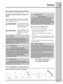
[mpoAant
Safety
Recognize
labels
safety
Instructions
symbols,
words
and
Safety items throughout this manual are labeled
with a WARNING or CAUTION based on the risk
type as described below:
WARNING
This
symbol
to
situations
thatalerts
mayyou
cause
serious body harm, death
or property damage.
WHAT TO DO IF YOU SMELL GAS:
•
This symbol alerts you to
situations that may cause
bodily injury or property
damage.
CAUTION
Do not try to light any appliance.
Do not touch any electrical switch; do not use
any phone in your building.
Clear the room, building or area of all occupants.
Immediately call your gas supplier from a neighbor's phone. Follow the gas supplier's instructions.
If you cannot reach your gas supplier, call the
fire department.
Save these
for future
Preoinsta[[ation
Tools and materials
requirements
needed for installation:
OR
Universal wrench
supplied wkh
washer
instructions
reference.
OR
Adjustable
wrench
OR
3/8" or 10 mm
box wrench
AND
Ratchet and
socket
set
AND
Adjustable
plbrs
Carpenter's
level
Installation
Requirements
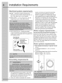
E ectrica
requirements
system
CIRCUIT - Individual, properly polarized and
grounded 15 amp. branch circuit fused with 15
amp. time delay fuse or circuit breaker.
POWER SUPPLY - 2 wire, with ground, 120 volt
single phase, 60 Hz, Alternating Current.
OUTLET RECEPTACLE - Properly grounded
3-prong receptacle to be located so the power
supply cord is accessible when the washer is in
an installed position.
Groul
wall
Do not, under
"_
any circumstances, |
cut, remove,
/
or bypassthe
|
grounding prong, j)
supply cord having an equipment-grounding
conductor and a grounding plug, the plug
MUST be plugged into an appropriate, copper
wired receptacle that is properly installed and
grounded in accordance with all local codes and
ordinances or in the absence of local codes,
with the National Electrical Codes, ANSI/NFPA
70 (latest edition). If in doubt, call a licensed
electrician. DO NOT cut off or alter the grounding
prong on the power supply cord. In situations
where a two-slot receptacle is present, it is
the owner's responsibility to have a licensed
electrician replace it with a properly grounded
three prong grounding type receptacle.
Water
supply
requirements
Hot and cold water faucets MUST be installed
within 42 inches (107 cm) of your washer's water
inlet. The faucets MUST be 3/4 inch (1.9 cm) with
threading for laundry hose connection. Water pressure MUST be between 30 and 120 psi. Pressure
difference between hot and cold cannot be more
than 10 psi. Your water department
of your water pressure.
Drain system
can advise you
requirements
1. Drain capable of eliminating 17 gals (64.3 L) per
minute.
Powercord with
2. A standpipe diameter of 1-1/4 in. (3.18 cm)
minimum.
3. The standpipe height above the floor should be:
Minimum height: 24 in. (61 cm)
Maximum height: 96 in. (244 cm)
Grounding
requirements
96 _
(244cm)
[lrlax.
(61 C/r I)
mln"
1. The washer MUST be grounded. In the event
of malfunction or breakdown, grounding will
reduce the risk of electrical shock by a path of
least resistance for electrical current.
2. Since your washer is equipped with a power
m
Installation
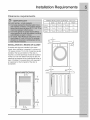
Clearance
Requirements
requirements
MINIMUM INSTALLATION CLEARANCES
iNSTALLATiON
iN A RECESS
- Inches (cm)
SIDES
REAR
TOP
FRONT
Alcove
0" (0 cm)
0" (0 cm)*
0" (0 cm)
n/a
UnderCounter
0" (0 cm)
0" (0 cm)*
0" (0 cm)
n/a
Closet
0" (0 cm)
0" (0 cm)*
0" (0 cm)
1" (2.54 cm)
OR CLOSET
If washer and dryer are installed in the same
closet, door ventilation is required: A minimum of
120 square inches (774.2 cm 2)of opening, equally
divided at the top and bottom of the door, is
required. Louvered openings should be located 3
inches (7.6 cm) from bottom and top of door. Air
openings are required to be unobstructed when a
door is installed. A Iouvered door with equivalent
air openings for the full length of the door is
acceptable.
1"
""='€_
(2.54cm)
lo
io
H
i i_
i i
O0
II
H
0" -...........'li_i i_II,._
(Ocrn}
ii
_=''=
i
r (7.6crn]
closet door
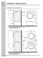
installation Requirements
Installed
washer
to clear
dimensions
(128.53cm)*
open
door
to front
(80.01cm)
of closed
door
(68.58cm)
water
supply
connection
on rear of unit 1
power
cord
on rear
of unit 3
drain hose
on rear of unit 2
38.00"
(96.52cm)
freestand
floor
!
washer
on floor
line
53.00"
(134.62cm)
washer
mounted
on
optional
pedestal
floor
line
* To obtain
these
minimal
depth dimensions,
dryer must either be vented
straight
back or with
Connection
of water
inlet hose on Steam
Models
adds 3/4 in. (2 cm) to installation
depth.
I Hot and cold inlet hose length
approximately
48.5 inches
(123cm)
2 Drain hose length approximately
59 inches
(150cm).
3 Power
supply
cord length
approximately
60 inches
(152.5cm).
a quick-turn
90 ° elbow.
50.6" (128.5cm) _
to clear open
door
27.00
31.50"
(80cm)*
-to front of closed
door
(68.5cm)
electrical
supply
on
rear of
75.75"
(192.5cm)
dryer
water
supply
connection
on rear of
washer
1
centerline
height
for
rear vent
gas supply
pipe on rear
of gas unit
!
* To obtain
these
minimal
depth dimensions,
dryer must either be vented
straight
Connection
of water
inlet hose on Steam
Models
adds 3/4 in. (2 cm) to installation
I Hot and cold inlet hose length
approximately
48.5 inches
(123cm)
2 Drain hose length
approximately
59 inches
(150cm).
3 Power
supply
cord length
approximately
50 inches
(152.5cm).
41.00"
(105cm)
power cord
on rear of
39.00"
(99cm)
drain hose
on rear of
washer
2
back or with
depth.
a quick-turn
90 ° elbow.
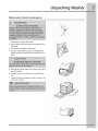
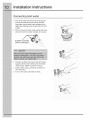
Unpackin
Removing
foam
packaging
1. Temporarily remove door tape.
2. Open washer door and remove everything from
the drum.
3. Close door and reapply door tape.
4. Using a rug, blanket or piece of cardboard to
protect the floor, carefully lay the washer on it's
back.
5. Remove styrofoam base and shipping plug and
set them aside.
6. Carefully return the washer to an upright position.
7. Carefully move the washer to within 4 feet (1 m)
of its final location.
!
Washer
Unpacking
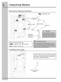
Removing
Washer
shipping
hardware
1 SHIPPING FORK
[] 5 P CLAMPS
® 5 SPACER
sX
•
UNWERSAI
"
BOLTS
®_
WRENCH
(SUPPLIED)
_/_
Remove all of the following:
1 SHIPPING FORK ® 5 SPACERS
[]5PCLAMPS
Installing
05BOLTS
hole pmugs
Locate 7 hole plugs in the small bag supplied
with washer instruction guides. Insert them in
the holes in washer back panel.
/
A 7 HOLE PLUGS
(IN BAG)
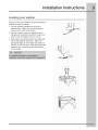
Installation instructions
Leveling
your washer
Excessive noise and vibration can be prevented by
properly leveling the washer.
1. For free standing installation and with the
washer within 4 feet (1 m) of its final location,
place a level on top of the washer.
2. Use the universal wrench to adjust the leveling legs so the washer is level front-to-rear and
side-to-side, and stable corner-to-corner.
3. Press down on alternate corners and sides and
feel for the slightest movement. Adjust the
appropriate leg(s) so the washer sits solidly on
the floor on ALL four legs. Keep the leveling leg
extension at a minimum for best performance
of the washer.
installation
Connecting
instructions
inlet water
1. Run some water from the hot and cold faucets
to flush the water lines and remove particles
that might clog the water valve screens and to
determine which faucet is hot and which is cold
supply.
2. Look in the end of each water supply inlet hose
and verify that the rubber washers are in place.
RUBBER WASHERS
MUST BE PRESENT
3. Connect the HOT inlet hose to the HOT water
supply and the COLD inlet hose to the COLD
water supply. Tighten by hand until snug.
4. Tighten each supply connection another 2/3
turn with pliers.
5. Turn on the water and check for leaks.
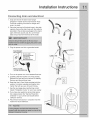
Installation
Connecting
drain and electrical
1. Snap one end of the drain hose hanger
(shipped in washer drum) onto the drain hose.
Continue wrapping it around the hanger and
snap it in place.
.
Place the hook end of the drain hose in the drain
opening. Secure the drain hose with the cable tie
(provided in the enclosure package) to the standpipe, inlet hose, laundry tub, etc. so the hose
does not pull out from the force of the water.
3. Plug the power cord into a grounded outlet.
¸wall
CABLE T[ E
I
I
Instructions
Installation
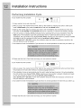
Pe#ormin9
Instructions
Installation
If your washer has this console:
Cycle
|
I
L
!
"_
:. liooo
i io°
o
1. Empty washer's drum and close door.
2.After you plug in the washer the first time: wake up the washer by pressing any button, rotate cycle
knob to hand wash cycle, press the start button and then the cancel button.
3.Wake up the washer again by pressing any button, then immediately and simultaneously press and
hold both the eco friendly and my favorite buttons for 5 seconds, or until the LCD display changes.
4.The LCD window will display INSTAL EMCLE and show estimated time of cycle completion. Press the
start button. The Installation Cycle will automatically test for if water has been turned on. At cycle
completion, the LCD window may display INSTAL PASS!, meaning your new washer is properly installed
and ready for use. If it prompts an action such as no WATER, EHECH HOSES or
CALL SERUICE 8-?7 H35 328-?, review the installation steps and make the necessary corrections before you attempt to use the washer.
5.Your washer will exit the Installation Cycle and return to normal operation the next time you wake it up.
6.Please read the Use & Care Guide and enjoy your new premium washer!
If your washer has this console:
{
L_
f
_@
=,=_=,=o Oo
1 .After you plug in the washer the first time: wake up the washer by pressing any button and then follow
the prompts on the LCD User Interface, including language selection.
2.The Installation Cycle will automatically test for, and if water has been turned on. At cycle completion,
the LCD window may display INSTAL PASS!, meaning your new washer is properly installed and ready
for use. If it prompts an action such as [10 WATER, CHECH HOSES or
CALL 5ERUICE 8-?-? H3S 328-?, review the installation steps and make the necessary corrections before you attempt to use the washer.
3.Your washer will exit the Installation Cycle and return to normal operation the next time you wake it up.
4.Please read the Use & Care Guide and enjoy your new premium washer!
Reversing
Preparing
to reverse
door
swing
1 Be sure you have adequate swing area before reversing door.
2
You will need a screw driver with a #2 square bit.
3
Protect flat work surface, such as top of washer or floor near
washer, with a soft cloth or towel.
4
Be sure washer is unplugged from power source!
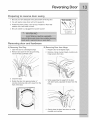
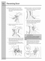
Removing
door
A) Removing
Trim Ring
Door
Tools needed:
%
Screwdrivers with
#2 square &
straight bit
and hardware
B) Removing
Door from Hinge
1 Open the door to a 90 degree angle.
1 Reopen door to 90 degree angle.
2
Remove and save the trim plug and long,
course-thread, panhead screw.
2
Remove 4 long, course-thread,
hinge screws from door.
3
Close the door.
4
Rotate the door trim approximately 3/4"
counter-clockwise and pull it away from the
front of the door.
3
While supporting the weight of the door
with both hands, separate the door from the
hinge.
counter-sunk
/
/
!
/
t
4
Gently place the door face down on a flat,
covered work surface.
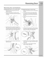
Reversing
C) Removing
Door
Hinge from Front Panel
1 With the hinge in open position, remove 2
short, course-thread, panhead screws on
hinge plate.
D) Removing
Door Lock from Front Panel
1 Remove 2 short, course-thread,
screws from the door lock.
panhead
Slide the lock toward the outer edge of the
front panel. Pivot the lock slightly outward
while slowly pulling it through opening to
expose the attached harness.
2
Remove 3 short, fine-thread, counter-sunk
screws in hinge side.
3
Slide the hinge toward the center of the front
panel, and then pivot the hinge inward while
slowly pulling it away from the front panel to
expose the attached harness.
4
Lift up on the tab and the release harness
from the retainer, allowing the harness to lay
outside the front panel.
Release the harness from the terminal
with the small lever on back of the lock.
S0eparate the harness from the lock,
allowing the harness to lay outside the front
panel.
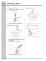
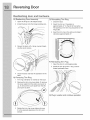
Reversing
Reversing
door
E) Reattaching
Door Lock to Front Panel
Door
and hardware
F) Reattaching
Hinge to Front Panel
1 Rotate the door lock and move it to the
opposite opening.
1 Rotate the hinge and move it to the opposite
opening.
2
2
Connect the harness to the hinge retainer
by inserting it in the retention terminal and
gently pushing until you hear the fastening
tab click.
3
Gently pull on the harness to be sure it is
secure.
4
Use the side locating pins to align the hinge
and install 1 short, fine-thread, counter-sunk
screw in the center hole of hinge side.
5
Install the other 2 short, fine-thread, countersunk screws in the upper and lower holes of
hinge side.
6
Install 2 short, course-thread,
screws through hinge plate.
3
Connect the harness to the door lock by
inserting it in the terminal and firmly pushing
it in place.
Insert the harness connection through the
front panel first, and then pivot the lock until
it is flush. Slide the lock toward the center of
the front panel until the screw holes line up.
4
Secure the lock with 2 short, course-thread,
panhead screws.
panhead
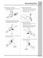
Reversing
G) Removing
1
Striker
Door
Plate
I) Removing
Remove 2 long, course-thread,
screws and striker plate.
Hole Plug
counter-sunk
iI_I_I i iii_ii_
2 Set the striker plate to the side for later.
H) Removing
Latch
Indicator
1 Insert flat blade screwdriver
latch indicator.
into open slot of
2
Gently pry upward to release tab.
3
Pull the indicator out and set it aside.
1 Insert flat blade screwdriver
hole plug.
into open slot of
2
Gently pry upward to release tab.
3
Pull the hole plug out and set it aside.
Reversing
J) Reinserting
Latch Indicator
K) Reattaching
1 Rotate the latch indicator and move it to the
opposite hole in the door.
Striker
Door
Plate
1 Rotate the striker plate and move it to the
opposite side of door above the indicator.
2
Reattach with 2 long, course-thread,
counter-sunk screws.
insert indicator
_slot
7
2
Firmly insert the two small tabs on either
side of the latch indicator into the two slots
on either side of the hole in the door.
L) Reinserting
Hole Plug
1 Rotate the hole plug and move it to the
opposite hole in the door.
2
Firmly insert the two small tabs on either
side of the hole plug into the two slots on
either side of the hole in the door.
\
insert tab
3
Firmly press downward on the indicator until
the tab snaps _n place.
insert tab
3
L
pressdown
and snap
Firmly press downward on the hole plug until
the tab snaps _n 31ace.
Reversing
Reattaching
M) Reattaching
Door
door and hardware
Door Assembly
O) Reinstalling
Trim Ring
1 Open the hinge to a 90 degree angle.
1 CIosethe door.
2
2
Orient the trim so 12 position is
approximately 3/4"to the left of top center.
The opening in the trim ring should be on the
hinge side.
3
Insert the trim ring in the slots and rotate it
clockwise approximately 3A".
Install the door onto the hinge locating pins.
\
\
3
Secure the door with 4 long, course-thread.
counter-sun k screws.
P) Reinstalling
Trim Plug
1 Open the door to a 90 degree angle.
2
4
Install the trim plug with 1 long, coursethread, panhead screw.
Close the door and test the operation of the
latch.
N) Reversing Trim Ring
1 Trim ring orientation is marked on the back.
2
Remove the trim nng cover plate. To remove
the cover plate from the right, pivot point is
up. To remove the cover plate from the left,
pivot point is down.
Q) Plug in washer and continue operation.
3 Rotate the trim ring cover plate and move
it to the opposite opening in the trim and
reinsert.
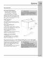
Options
MATCHING STORAGE PEDESTAL
Island White Pedestal - P/N EPWD15iW
Mediterranean Blue - P/N EPWD15MB
Silver Sands Pedestal- P/N EPWD15SS
Turquoise Sky Pedestal - P/N EPWD15TS
A storage pedestal accessory, specifically
designed for this washer may be used to elevate
the dryer for ease of use. This pedestal will add
about 15" (38.1cm) to the height of your unit for a
total height of 53" (134.62 cm).
DRYER STACKING KiT
P/N 134700400
A kit for stacking the matching dryer on top of
this washer is available with the purchase of the
matching dryer.
0
DRAIN HOSE EXTENSION KIT
P/N 137098000
in order to reach standpipe heights or distances
beyond the reach of the drain hose supplied, order
the DRAIN HOSE EXTENSION KIT.
MOBILE HOME INSTALLATION
P/N 137067200
KIT
Installation in a mobile home requires the use of a
MOBILE HOME INSTALLATION KIT.
UNIVERSAL APPLIANCE WRENCH
P/N 137019200
Your washer was supplied with a UNIVERSAL
APPLIANCE WRENCH. If you desire another
wrench, you may order one.
Repmacement paAs: 1-877-4ELECTROLUX
If replacements parts are needed for your washer,
contact the source where you purchased your
washer, call 1-877-4ELECTROLUX (1-877-4353287), or visit our website,
www.electroluxappliances.com,
for the Electrolux
Authorized Parts Distributor nearest you.
(1-877-435-3287}
Notes