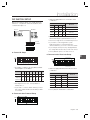
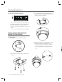
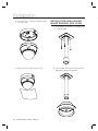
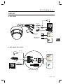
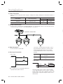
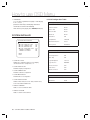
1
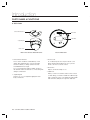
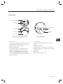
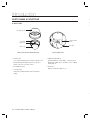
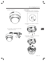
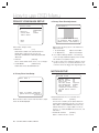
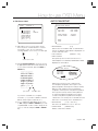
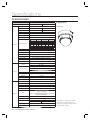
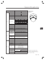
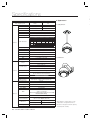
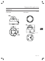
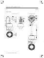
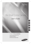
SCC-C6323
SCC-C6325
SCC-C7325
10x Mini Smart
Dome Camera
user manual
ENG
FRE
GER
SPA
ITA
imagine the possibilities
Thank you for purchasing this Samsung product.
To receive more complete service,
please register your product at
www.samsung.com/global/register
Safety information
C
CAUTION
1
RISK OF ELECTRIC SHOCK.
DO NOT OPEN
2
CAUTION: TO REDUCE THE RISK OF ELECTRIC SHOCK, DO NOT REMOVE REAR COVER. NO USER SERVICEABLE PARTS
INSIDE. REFER TO QUALIFIED SERVICE PERSONNEL..
This symbol indicates high voltage is present inside. It is dangerous to make any kind of
contact with any inside part of this product.
3
4
5
This symbol alerts you that important literature concerning operation and maintenance has
been included with this product.
6
7
WARNING
8
• To prevent damage which may result in fire or electric shock hazard, do not expose this appliance to rain or
moisture.
9
WARNING
1. Be sure to use only the standard adapter that is specified in the specification sheet. Using any other adapter
could cause fire, electrical shock, or damage to the product
2. Incorrectly connecting the power supply or replacing battery may cause explosion, fire, electric shock, or
damage to the product.
3. Do not connect multiple cameras to a single adapter. Exceeding the capacity may cause abnormal heat
generation or fire.
4. Securely plug the power cord into the power receptacle. Insecure connection may cause fire.
5. When installing the camera, fasten it securely and firmly. A falling camera may cause personal injury.
6. Do not place conductive objects (e.g. screwdrivers, coins, metal things, etc.) or containers filled with water
on top of the camera. Doing so may cause personal injury due to fire, electric shock, or falling objects.
7. Do not install the unit in humid, dusty, or sooty locations. Doing so may cause fire or electric shock.
8. If any unusual smells or smoke come from the unit, stop using the product. In such case, immediately
disconnect the power source and contact the service center. Continued use in such a condition may cause
fire or electric shock.
9. If this product fails to operate normally, contact the nearest service center. Never disassemble or modify
this product in any way. (SAMSUNG is not liable for problems caused by unauthorized modifications or
attempted repair.)
10.When cleaning, do not spray water directly onto parts of the product. Doing so may cause fire or electric shock.
11.If the camera is installed or rebooted after power failure when ambient temperature is below the freezing point,
the dome cover is frosted. In this case, the frost will be disappeared after 3 hours after turning on the power.
(It is noted that lowest guaranteed operating temperature is -45º C (-49º F) without wind.)
2 – 10X MINI SMART DOME CAMERA
Safety information
CAUTION
1. Do not drop objects on the product or apply strong shock to it. Keep away from a location subject to
excessive vibrationor magnetic interference.
2. Do not install in a location subject to high temperature (over 50°C), low temperature (below -10°C), or high
humidity. Doing so may cause fire or electric shock.
3. If you want to relocate the already installed product, be sure to turn off the power and then move or reinstall
it.
4. Remove the power plug from the outlet when then there is a lightning. Neglecting to do so may cause fire or
damage to the product.
5. Keep out of direct sunlight and heat radiation sources. It may cause fire.
6. Install it in a place with good ventilation.
7. Avoid aiming the camera directly towards extremely bright objects such as sun, as this may damage the
CCD image sensor.
8. Apparatus shall not be exposed to dripping or splashing and no objects filled with liquids, such as vases,
shall be placed on the apparatus.
ENG
9. The Mains plug is used as a disconnect device and shall stay readily operable at any time.
English – 3
Important Safety Instructions
1. Read these instructions.
2. Keep these instructions.
3. Heed all warnings.
4. Follow all instructions.
5. Do not use this apparatus near water.
6. Clean only with dry cloth.
7. Do not block any ventilation openings. Install in accordance with the manufacturer’s instructions.
8. Do not install near any heat sources such as radiators, heat registers, or other apparatus (including amplifiers) that
produce heat.
9. Do not defeat the safety purpose of the polarized or grounding-type plug. A polarized plug has two blades with
one wider than the other. A grounding type plug has two blades and a third grounding prong. The wide blade or
the third prong is provided for your safety. If the provided plug does not fit into your outlet, consult an electrician
for replacement of the obsolete outlet.
10.Protect the power cord from being walked on or pinched particularly at plugs, convenience
receptacles, and the point where they exit from the apparatus.
11.Only use attachments/accessories specified by the manufacturer.
12.Use only with cart, stand, tripod, bracket, or table specified by the manufacturer, or sold
with the apparatus.
13.Unplug this apparatus when a card is used. Use caution when moving the cart/ apparatus
combination to avoid injury from tip-over.
14.Refer all servicing to qualified service personnel. Servicing is required when the apparatus has been damaged in
any way, such as powersupply cord or plug is damaged, liquid has been spilled or objects have fallen into the
apparatus, the apparatus has been exposed to rain or moisture, does not operate normally, or has been dropped.
4 – 10X MINI SMART DOME CAMERA
Contents
Introduction
Features
7
Product & Accessories
8
Parts Name & Functions
10
Installation
DIP Switch Setup
13
Installation using Surface mount on the Ceiling
14
Installation using Ceiling Mount Bracket (SCC-C7325)
16
Installation using Wall Mount Bracket (SCC-C7325)
17
Cabling
19
Operation
21
Preset and Pattern Function Pre-Check
21
Starting OSD Menu
21
Reserved Preset
21
Preset
22
Auto Pan
22
Pattern
22
Scan
23
Schedule
23
Other Functions
23
OSD Display of Main Screen
24
General Rules of Key Operation for Menu
25
Main Menu
25
System Information
25
Display Setup
25
English – 5
ENG
Check points before operation
Contents
How to use OSD Menu
F
Privacy Zone Mask Setup
26
Motion Setup
26
Function Setup
27
PRESET Setup
28
Auto Pan Setup
29
Pattern Setup
30
Scan Setup
30
Schedule Setup
32
Camera Setup
33
System Setup
34
System Initialize
36
❖
❖
Specifications
Specifications
38
Dimension
41
❖
6 – 10X MINI SMART DOME CAMERA
Introduction
FEATURES
❖ Camera Specifications
• CCD Sensor
: 1/4” Interline Transfer CCD
• 7 rules of Schedule can be assigned by day and
time. Appropriate actions (such as Home, Preset,
Auto Pan, Pattern, Scan) can be defined for each
rule. Also, it is possible to make rule by Weekday
and Allday to simplify the rule.
: x10 Optical Zoom, x10
• Zoom Magnification
Digital Zoom (Max x 100 Zoom)
• Day & Night Function
❖ PTZ(Pan/Tilt/Zoom) Control
• Various Focus Mode: Auto-Focus / Manual Focus
/ Semi-Auto Focus.
• With RS-485 communication, max. 255 of
cameras can be controlled at the same time.
• Independent or General Camera Characteristic
Setup in Preset operation
• Pelco-D/ Pelco-P, Samsung protocol can be
selected as a control protocol in the current
version of firmware.
❖ Powerful Pan/Tilt Functions
• Max. 360°/sec high speed Pan/Tilt Motion
• Using Vector Drive Technology, Pan/Tilt motions
are accomplished in a shortest path. As a result,
time to target view is reduced dramatically and the
video on the monitor is very natural to watch.
• Owing to zoom-proportional pan/tilt speed,
camera can be moved to a desired position in
accurate manner even though zoom ratio is high.
❖ Preset, Pattern, Auto Pan, Scan, Privacy
Mask, Schedule and More…
• MAX. 127 Presets are assignable and
characteristics of each preset can be set up
independently, such as White Balance, Auto
Exposure, Label and so on.
• Max. 8 Auto Pan can be stored. This enables to
move camera repetitively between two preset
positions with designated speed.
• Max. 4 of Patterns can be recorded and
executed. This enables for camera to track a
surveillance trajectory as closely as possible which
are recorded from operator’s motion of joystick.
• Max. 8 Scan can be stored. To compose a
surveillance trajectory, the Group can have max.
20 entities of Preset/Pattern/Scan functions. This
enables for camera to move a combinations of
those functions repetitively.
• OSD menu is provided to display the status
of camera and to configure the functions
interactively.
• Currently, 7 Languages are supported for
OSD Menu: [ENGLISH/ESPAÑOL/FRANÇAIS/
DEUTSCH/ITALIANO/РУССКИЙ/PORTUGUÊS]
• The information such as Camera ID, Pan/Tilt/
Zoom/Direction, Alarm Input & Output, date/time,
current temperature and Preset can be displayed
on screen.
• Each display item can be turned On or Off
independently.
❖ Alarm I/O Functions
• 2 alarm sensor Inputs and 1 relay output are
available.
• To reject external electric noise and shock
perfectly, alarm sensor Input is decoupled with
photo coupler.
• If an external sensor is activated, camera can be
set to move to the corresponding Preset position.
• Relay output can be assigned to work with a
certain preset.
❖ Reserved Presets for Special Purpose
• Besides regular 127 presets, direct calling of
reserved presets enables to set up many of
camera functions with without using OSD menu.
For more information, refer to “Reserved Preset” in
this manual.
• Max. 4 Masks are settable independently to
protect privacy zone. The mask is arbitrary-sized
rectangular and locate any location in view space.
English – 7
ENG
• For jog operation using a controller, since ultra
slow speed 0.05°/sec can be reached, it is very
easy to locate camera to desired target view.
❖ OSD(On Screen Display) Menu
Introduction
PRODUCT & ACCESSORIES
❖
❖ Product & Accessories (SCC-C6323)
• Main Product
Main Body
Surface Mount Bracket
• Accessory
G
Manual
Screw & Plastic Anchor (4Pcs)
❖ Product & Accessories (SCC-C6325)
• Main Product
Main Body
Surface Mount Bracket
• Accessory
Screw & Plastic
Anchor (4Pcs)
Terminal Block
Torx Screw Driver
Ú Mount Bracket Option : Please use SADT-937WM for this purpose.
8 – 10X MINI SMART DOME CAMERA
Surface Mount
Gasket
Manual
Introduction
❖ Product & Accessories (SCC-C7325)
• Main Product
Main Body
Sun Shield Housing
• Accessory
ENG
Terminal Block
Torx Screw Driver
Manual
• Mount Bracket Option
Wall Mount Bracket (SADT-732WM)
Ceiling Mount Bracket (SADT-732CM)
English – 9
Introduction
PARTS NAME & FUNCTIONS
❖
❖ SCC-C6323
Surface Mount Bracket
DIP Switch
Cable Duct
Separating Slit
Dome Cover
Main Unit / Surface Mount Bracket
• Surface Mount Bracket
This is used to install the camera directly on the
ceiling. After separating this cover first and then
attach this directly to ceiling. Camera must be
assembled at the last stage.
Do not use this bracket when installing camera on
the wall with wall mount bracket or on the ceiling with
ceiling mount bracket.
• Separating Slit
Using a coin, you can separate upper part lower
body of the dome.
10 – 10X MINI SMART DOME CAMERA
Back of Main Unit
• Dome Cover
Do not detach protection vinyl from dome cover
before finishing all installation process to protect
dome cover from scratches or dust.
• DIP Switch
Adjusts camera ID and protocols.
• Cable Duct
When you want to install the camera on the surface
of hard ceiling, you need to handle the cable through
side of the dome. In this case, break the side wall bit
and make the cable pass through the cable duct.
Introduction
❖ SCC-C6325
Surface Mount Bracket
Mounting Hole
Cabling Terminal
Block
Main Body
Lockup Screw
DIP Switch
Dome Cover
Main Unit / Surface Mount Bracket
Back of Main Unit
ENG
• Dome Cover
Do not remove the protection vinyl from dome cover
before finishing all installation process to protect
dome cover from scratches or dust.
• Surface Mount Bracket
This is used to install the camera directly on the
ceiling. After separating this cover, mount this
bracket on to ceiling. Main body of the camera is
going to be assembled again in the last stage.
Do not use this bracket with wall mount bracket or
ceiling mount bracket.
• Lockup Screw
Fixes main unit brackets like surface, wall, and
ceiling.
• Cabling Terminal Block
During installation, Power, Video, Communication,
Alarm Input cables are connected on to this cabling
terminal block.
• DIP Switch
Adjusts camera ID and protocols.
English – 11
Introduction
PARTS NAME & FUNCTIONS
D
❖ SCC-C7325
B
s
c
Sun Shield Housing
Cabling Terminal
Block
Main Body
Lockup Screw
DIP Switch
Dome Cover
Main Unit / Surface Mount Bracket
• Dome Cover
Do not remove the protection vinyl from dome cover
before finishing all installation process to protect
dome cover from scratches or dust.
• Sun Shield Housing
• Lockup Screw
Fixes main unit brackets like surface, wall, and
ceiling.
Back of Main Unit
❖
• Cabling Terminal Block
During installation, Power, Video, Communication,
Alarm Input cables are connected on to this cabling
terminal block.
• DIP Switch
Adjusts camera ID and protocols.
❖
12 – 10X MINI SMART DOME CAMERA
Installation
• Select the appropriate Protocol with DIP switch
combination.
DIP SWITCH SETUP
Before you install the camera, you should set the DIP
switches to configure the camera ID, Baud rate, and
communication protocol.
Protocol
Auto Select
Switch State
Buad Rate
Protocol
Pin1
Pin2
Pin3
Pin4
OFF
OFF
OFF
OFF
Auto Protocol
ON
OFF
OFF
OFF
Pelco-D
OFF
ON
OFF
OFF
Pelco-P
ON
ON
OFF
OFF
Samsung
• If you set the protocol as Auto Protocol, camera
will automatically recognize the kind of Protocol.
• Auto Protocol supports Pelco-D and Samsung Protocol.
RS-485
Terminate
• If you want to control using DVR or system
keyboard, their protocol must be identical to
camera. Otherwise, you can not control the camera.
ID Setting (1~255)
• If you changed camera protocol by changing DIP S/W,
the change will be effective after you reboot the camera.
• Factory default of protocol is “Auto Protocol
❖ Camera ID Setup
ON
ON
1
• ID number of camera is set using binary number.
The example is shown bellow.
Pin
1
2
3
4
5
6
7
ID Value
1
2
4
8
16
32
64 128
ex) ID=5
on
off
on
off
off
off
off
off
ex) ID=10 off
on
off
on
off
off
off
off
ENG
❖ Communication Baud rate Setup
2
3
4
5
6
7
8
• Select the appropriate Baud rate with DIP switch
combination.
8
Switch State
• The range of ID is 0~255. Factory default of
Camera ID is 1.
• If you want to control a certain camera, you must
match the camera ID with Cam ID setting of DVR
or Controller.
Protocol
Pin5
Pin6
Pin7
OFF
OFF
OFF
2400 BPS
4800 BPS
ON
OFF
OFF
OFF
ON
OFF
9600 BPS
ON
ON
OFF
19200 BPS
OFF
OFF
ON
38400 BPS
• Factory default of Baud rate is “9600 BPS”
❖ Communication Protocol Setup
ON ON
1
2
3
4
5
6
7
8
English – 13
Installation
❖ RS-485 Termination Resistor
③ Placing lower body to Surface Mount bracket.
The cable must be properly handled into hole of
bracket or side of lower body.
ON
ON
1
2
3
4
5
6
7
8
• Pin 8 is used for ON/OFF of RS-485 Termination.
Normally, it must be OFF state. Especially when
you have trouble with long Daisy chain style
connection, turn ON this termination switch of last
camera.
– Pin 8
RS-485 Termination Resistor (On/Off)
INSTALLATION USING SURFACE
MOUNT ON THE CEILING
❖ SCC-C6323
① Setup DIP Switch (see previous page).
④ Make sure stopper pin of bracket pin is located
the rightmost side of lower body groove as
shown in the picture. Press the dome and turn
clockwise till the pin is located leftmost side
of groove. Detach protection vinyl from dome
cover.
② Screw surface mount bracket to ceiling with 4
screws.
G
14 – 10X MINI SMART DOME CAMERA
Installation
⑤ Tighten locking screw.
❖ SCC-C6325
① To pass cables to upside of ceiling, please,
make about ũ60mm hole on the ceiling panel.
② Screw surface mount bracket to ceiling with
4 screws.
ENG
⑥ Connect Video, communication, power cable
properly. (see next section)
③ Wire cables to terminal block and connect the
terminal blocks to main unit.
English – 15
Installation
④ Screw main unit to surface mount bracket with
4 lock-up screws.
INSTALLATION USING CEILING
MOUNT BRACKET (SCC-C7325)
① Install ceiling mount bracket on the ceiling using
4 screws provided.
⑤ Detach protection vinyl from dome cover.
16 – 10X MINI SMART DOME CAMERA
② Turn sunshield clockwise after locating it in the
pipe head of ceiling mount properly.
Installation
③ After wiring cables to terminals, plug the
terminals into the bottom of main unit. Then, fix
the main unit with sunshield with 4 screws.
INSTALLATION USING WALL
MOUNT BRACKET (SCC-C7325)
① Use the 4 screws (provided) to secure the wall
mount bracket to the wall.
④ Detach protection vinyl from dome cover.
English – 17
ENG
② Turn sunshield clockwise after locating it in the
pipe head of wall mount properly.
Installation
③ After wiring cables to terminals, plug the
terminals into the bottom of main unit. Then, fix
the main unit with sunshield with 4 screws.
C
❖
❖
④ Detach protection vinyl from dome cover.
18 – 10X MINI SMART DOME CAMERA
Installation
CABLING
❖ SCC-C6323
Dual Voltage
DC 12V/AC 24V
BNC Video
Controller/DVR
1 (Black) : IN COM
2 (Yellow) : IN 1
3 (Brown) : IN 2
Sensors
ENG
4 (Red) : Relay Out
5 (Orange) : Relay Out
IrDA
Sensor
Door
Switch
Lamp
Relay Out
❖ SCC-C6325/ SCC-C7325
Dual Voltage
DC 12V/AC 24V
IrDA
Sensor
Door
Switch
Relay Out
Relay Out
Controller/DVR
Sensors
BNC Video
Lamp
Relay Out
Cabling Terminal Block
English – 19
Installation
❖ Power Connection
C
• Please, check the voltage and current capacity of rated power carefully. Rated power is indicated in the back of
main unit.
Power Mode
Input Voltage Range
DC 12V
AC24V
Power Consumption
C6323/ C6325
C7325
DC 11V ~ 15V
8W
12W
AC 20V ~ 29V
10W
21W
❖ RS-485 Communication
• For PTZ control, connect this line to keyboard and DVR. To control multiple cameras at the same time, RS-485
communication lines of them is connected in parallel as shown below.
P
F
Keyboard Controller DVR
A
❖ Video Connection
• Connect with BNC coaxial cable.
❖ Alarm Input Connection
• Sensor Input
IN T ER N AL
INTERNAL
IN1
If you want to use Alarm Input, the types of sensor
must be selected in OSD menu. The sensor types
are Normal Open and Normal. If sensor type is
not selected properly, the alarm can be activated
reversely.
Normal Open Sensor output is turned ON when
(N.O)
sensor is activated
Normal Close
(N.C)
Sensor output is turned OFF when
sensor is activated
S
IN 2
• Relay Output
IN COM
Internal
Relay Out
Power
Relay Out
R
It is noted that short circuit between GND and
Input pin means alarm activation.
20 – 10X MINI SMART DOME CAMERA
There are 4 Alarm Outputs and all of them are Relay
contact type. Therefore, you do not have to care about
polarity, AC/DC, and isolations between channels. Care
must be taken for the power capacity of relay contact
written above.
Operation
CHECK POINTS BEFORE OPERATION
• Before power is applied, please check the cables carefully.
• The camera ID of the controller must be identical to that
of the camera to be controlled. The camera ID can be
checked in the System Information of OSD Menu.
• If your controller supports multi-protocols, the protocol
must be changed to match to that of the camera.
various functions using keyboard controller as well as
simplify the interface with DVR and IP equipments.
• Function
<Go Preset> [95]
: Enters into OSD menu
<Go Preset> [131~134]
: Runs Pattern Function 1 ~ 4
<Go Preset> [141~148]
: Runs Auto Pan Function 1 ~ 8
: Runs Scan Function 1 ~ 8
• If you changed camera protocol by changing DIP switch,
the change will be effective after you reboot the camera.
<Go Preset> [161]
: Sets Relay Output to OFF
<Set Preset> [161]
: Sets Relay Output to ON
• Since the operation method can be different for
each controller available, refer to the manual for your
controller if camera can not be controlled properly.
<Go Preset> [165]
: Auto Calibration ON
<Go Preset> [166]
: Auto Calibration OFF
<Go Preset> [167]
: Zoom Proportional Jog ON
PRESET AND PATTERN
FUNCTION PRE-CHECK
<Set Preset>[167]
: Zoom Proportional Jog OFF
<Go Preset> [170]
: Sets Camera BLC Mode to OFF
<Go Preset> [171]
: Sets Camera BLC Mode to HIGH
<Go Preset> [174]
: Sets Camera Focus Mode to
AUTO
<Go Preset> [175]
: Sets Camera Focus Mode to
Manual
<Go Preset> [176]
: Sets Camera Focus Mode to
SEMI-AUTO
<Go Preset> [177]
: Sets Day & Night Mode to
AUTO1
<Go Preset> [178]
: Sets Day & Night Mode to
NIGHT
<Go Preset> [179]
: Sets Day & Night Mode to DAY
<Go Preset> [190]
: Sets OSD Display Mode to
AUTO (Except Privacy Mask)
<Go Preset> [191]
: Sets OSD Display Mode to OFF
(Except Privacy Mask)
<Go Preset> [192]
: Setting OSD Display Mode to
ON (Except Privacy Mask)
<Go Preset> [193]
: Sets all Privacy Mask Display to
OFF
<Go Preset> [194]
: Sets all Privacy Mask Display to
ON
<Go Preset> [195]
: Heater ON (Turn off after 5mins
and switch to Auto mode)
<Go Preset> [196]
: Heater OFF (Turn off and switch
to Manual mode)
<Go Preset> [197]
: Fan ON (Turn off after 5mins
and switch to Auto mode)
<Go Preset> [198]
: Fan OFF (Turn off and switch to
Manual mode)
<Go Preset>[200]
: Digital Zoom ON
<Go Preset>[201]
: Digital Zoom OFF
• Check how to operate Preset, Scan, Auto Pan and
Pattern function with controller or DVR in advance to
operate camera function using them. (refer to your
System keyboard Manual)
• If controller or DVR has no pattern button or function,
use shortcut keys with preset numbers. For more
information, refer to “Reserved Preset” in this manual.
AUTO CALIBRATION
• If the camera is continuously subjected to very high
temperature (over 50°C or 122°F) environment for a
long time, it is possible for the camera to lose focus.
As a result, you will get blurry image. In this case, it is
recommended to turn on “AUTO CALIBRATION” by
running Preset 165.
• If you execute AUTO CALIBRATION, camera will
calibrate its focus at every 6 hours. To turn off this
function, please, Run Preset 166.
STARTING OSD MENU
• Function
Using the OSD menu, Preset, Pattern, Auto Pan,
Scan and Alarm Input function can be configured for
each application.
• Enter Menu
<Go Preset> [95]
RESERVED PRESET
• Description
Some Preset numbers are reserved for direct access
to specific functions in OSD menu. These direct
commands via preset provide quick execution of
English – 21
ENG
<Go Preset> [151~158]
Operation
• Run Auto Pan
PRESET
Method1) <Run Auto Pan> [Auto Pan NO.] [Enter]
• Function
Method2) <Go Preset> [Auto Pan NO.+140]
ex) Run Auto Pan 2 : <Go Preset> [142]]
Max. 127 positions can be stored as Preset position.
The Preset number can be assigned from 1 to 128. It
is noted that preset “95” is reserved for starting OSD
menu.
• Delete Auto Pan
Camera characteristics (i.e. White Balance, Auto
Exposure) can be set up independently for each
preset and they are adjusted by using OSD menu.
Four relay outputs can be controlled in conjunction
with one Preset.
PATTERN
To delete Auto Pan, use OSD menu.
• Function
Pattern Function enables to memorize the path (mostly
curve path) created by keyboard controller. By running
the pattern, the memorized path can be reconstructed
exactly as it memorized whenever required.
• Set Preset
<Set Preset> [1~128]
• Run Preset
S
4 Patterns are available and Maximum 1200
communication commands can be stored in a pattern.
<Go Preset> [1~128]
• Delete Preset
To delete Preset, use OSD menu.
• Set Pattern
Pattern can be created by one of following two
methods.
AUTO PAN
Method 1) <Set Pattern> [Pattern NO.]
– Pattern editing screen is displayed as bellow.
• Function
By using Auto Pan function, you can make camera
to move between 2 Preset positions repeatedly.
When Auto Pan function runs, camera moves
from the preset assigned as the 1st point to the
preset assigned as the 2nd point in CW(Clockwise)
direction. Then camera moves from the preset
assigned as the 2nd point to the preset assigned as
the 1st point in CCW(Counterclockwise) direction.
CW
on
cti
re
Di
W
CC
2nd Preset
on
cti
re
Di
1st Preset
In case that the preset assigned as the 1st point
is same as the preset assigned as the 2nd point,
camera turns on its axis by 360˚ in CW(Clockwise)
direction and then it turns on its axis by 360˚ in
CCW(Counterclockwise) direction.
Speed can be set up from 1˚/sec to 180˚/sec.
• Set Auto Pan
To set Auto Pan, use OSD menu.
22 – 10X MINI SMART DOME CAMERA
EDIT PATTERN 1
[NEAR:SAVE / FAR:DELETE]
0/0/X1/N
– Movement by Joystick and preset movement
can be memorized in a pattern.
– The rest memory size is displayed in progress
bar.
– To save the recording, press NEAR key and to
cancel, press FAR key.
Method 2) OSD Using OSD Menu:
See the section “How to use OSD Menu”.
S
y
Operation
• Run Pattern
Tuesday at 9:00AM. If you choose Weekday, camera
will move to Main gate everyday except weekend.
Method 1) <Run Pattern> [Pattern NO.]
ex) Run Pattern 2 : <Run Pattern> [2]
Method 2) <Go Preset> [Pattern NO.+130]
It is noted that due to the real time clock, the time data
will be kept regardless of blackout. The initial time and
day setup is essential to proper Schedule function.
ex) Run Pattern 2: <Go Preset> [132]
• Delete Pattern
• Set Schedule
Use OSD menu to delete a Pattern.
Use OSD Menu to create a Schedule
When the pattern is saved or executed, the PAN/TILT
is operated with Auto Flip OFF mode.
• Run Schedule
Use OSD Menu of Schedule Master Enable
• Delete Schedule
SCAN
Use OSD Menu to delete.
• Function
Dwell Time
Preset 1
OTHER FUNCTIONS
• Preset Lock
This function is made to protect preset data from
unauthorized overwriting. If Preset Lock is ON,
Preset save command using Hot Key is disabled
while Preset save using OSD Menu is acceptable.
• Power Up Action
Pattern 5
Auto Pan 5
Max 20 entities
• Set Scan
Use OSD Menu to create a Scan .
• Run Scan
Method1) <Run Scan> [Scan No.]
ex) Run Scan 2 : <Run Scan> [2]
Method2) <Run Preset> [Scan No.+150]
ex) Run Scan 2 : <Run Preset> [152]
• Delete Scan
Use OSD Menu to delete.
SCHEDULE
• Function
The Schedule function allows running an appropriate
function like Preset, Auto Pan, Pattern, Scan, Home
move at designated day and time. For example, if you
setup a rule Tuesday at 9:00AM and Preset 1 (say
Main Gate), the camera will move to main gate every
This function enables to resume the last action
executed before power down. Most of actions such
as Preset, Pattern, Auto Pan and Scan are available
for this function but Jog actions are not available to
resume.
• Auto Flip
In case that tilt angle arrives at the top of tilt orbit
(90°), zoom module camera keep moving to opposite
tilt direction (180°) to keep tracing targets. As soon
as zoom module camera passes through the top
of tilt direction (90°), images should be reversed
automatically and F appears in screen. If this
function is set to OFF, tilt movement range is 0 ~ 90°.
• Parking Action
This function enables to locate the camera to specific
position automatically if operator doesn’t operate the
controller for a while. The Park Time can be defined
as an interval from 1 minute to 4 hours.
• Alarm Input
2 Alarm Inputs are used. If an external sensor
is activated, camera can be set to move to
corresponding preset position. It is noted that the
latest alarm input is effective if multiple sensors are
activated.
English – 23
ENG
The Scan function allows running sequence of Presets,
Patterns and/or Auto Pans. Max 8 Scan can be stored.
Each Scan can have max 20 action entities which
can be preset, pattern or Auto Pan. Dwell time means
the time interval between actions and is adjustable in
the menu. Besides, there is an option number with
which Preset speed as well as the repetition number of
Pattern and Auto Pan can be set up.
Operation
• Privacy Zone Mask
• P/T/Z INFORMATION
To protect privacy, MAX. 4 Privacy Masks can be
created on the arbitrary position to hide objects such
as windows, shops or private house. With Spherical
Coordinates system, powerful Privacy Zone Mask
function is possible.
Current Pan/Tilt angle in degree, zoom magnification
and a compass direction.
• Camera ID
Current Camera ID(Address).
• Action Title
• GENERAL/SPECIAL Image Setup
WB(White Balance) and AE(Auto Exposure) can
be set up independently for each preset. There
are 2 modes, “General” mode & “Special” mode.
The General mode means that WB or AE can be
set up totally and simultaneously for all presets in
“ZOOM CAMERA SETUP” menu. The Special mode
means that WB or AE can be set up independently
or separately for each preset in each preset setup
menu. Each Special WB/AE value should activate
correspondingly when camera arrives at each preset
location.
During jog operation, General WB/AE value should be
applied. All Special WB/AE value will not be changed
regardless of General WB/AE value change.
• Semi Auto Focus
This mode enables to switch focus mode
automatically operation by operation. Manual focus
mode is selected during preset operation and Auto
focus mode is recovered if jog operation is started.
During Preset action, instead of auto focusing,
manual focus data stored when it is created will be
applied as soon as camera arrives to the preset.
This is helpful to get well-focused image in a short time.
Followings are possible Action Titles and their
meaning.
“SET PRESET ×××”
When Preset ××× is stored
“PRESET ×××”
When camera reach to
Preset ×××
“PATTERN ×”
When Pattern × is in action
“AUPx/PRESET XXX”
When Auto Pan x is in action
“UNDEFINED”
When undefined function is
called to run
• Preset Label
The Label stored for specific Preset.
• Alarm Information
This information shows current state of Alarm Input.
The “I” means Input and “O” is output. If an Input is
ON state it will show the number of input. If an Input
is OFF state, ‘-’ will be displayed. In the same way
“O:1” means output 1 is ON “O:-“ is OFF.
Ex) When Point 2 of inputs are ON, and Output 1 is
On, OSD will show as below
I:-2 0:1
OSD DISPLAY OF MAIN SCREEN
Lable 1
Preset
LABEL12345
PRESET1
Action Title
• Image Flip
Shows that images are currently reversed by Auto
Flip Function.
• Temperature
Current Temperature: Boxed “C” and “F” means
Celsius and Fahrenheit respectively
• Date/Time
Temperature
Alarm
Information
Date/Time
Camera ID
P/T/Z Information
Image Flip
Camera ID
24 – 10X MINI SMART DOME CAMERA
G
O
Displays Current Date and Time.
M
How to use OSD Menu
GENERAL RULES OF KEY
OPERATION FOR MENU
• The menu item surrounded with < > always means
it has its sub menu.
• For all menu level, to go into sub menu, press NEAR or
ENTER key.
• To go to up-one-level menu, press FAR key.
• To move from items to item in the menu, use joystick
in the Up/Down or Left/Right.
• To change a value of an item, use Up/Down of the
joystick in the controller.
SYSTEM INFORMATION
SYSTEM INFORMATION
FIRMWARE VER
COLOR SYSTEM
PROTOCOL
BAUD RATE
ADDRESS
1.0250
NTSC
SAMSUNG
9600
255
BACK
EXIT
• PressNEAR or ENTER key to save values and Press
FAR key to cancel values.
• FIRMWARE VER.
Shows current firmware version of camera.
MAIN MENU
• COLOR SYSTEM
Shows current analog video system of the camera.
Shows current Protocol for PTZ
control
<SYSTEM INFORMATION>
<DISPLAY SETUP>
<MOTION SETUP>
<FUNCTION SETUP>
<CAMERA SETUP>
<SYSTEM SETUP>
<SYSTEM INITIALIZE>
• BAUD RATE
Shows current Baud rate of PTZ
control.
• ADDRESS
Shows current Camera ID for PTZ
control.
EXIT
• SYSTEM INFORMATION
Shows System information such as current firmware
version and communication settings.
• DISPLAY SETUP
Enable/Disable of OSD display on Main Screen.
• MOTION SETUP
Setup for motion related settings
• FUNCTION SETUP
Setup for various functions such as Preset, Auto
Pan, Pattern, Scan and Schedule.
• CAMERA SETUP
Configure Camera related functions and data
DISPLAY SETUP
DISPLAY SETUP
CAMERA ID
PTZ INFORMATION
ACTION TITLE
RESET LABEL
ALARM I/O
DATE/TIME
<PRIVACY ZONE>
TEMPERATURE
BACK
EXIT
ON
AUTO
AUTO
AUTO
AUTO
ON
CELSIUS
This menu defines Enable/Disable of OSD display on
Main Screen. If an item is set to be AUTO, the item is
displayed only when the value of it is changed.
• CAMERA ID
[ON/OFF]
• SYSTEM SETUP
Configure for Basic system setup.
• PTZ INFORMATION
[ON/OFF/AUTO]
• SYSTEM INITIALIZE
Initializes system configuration and sets all data to
factory default configuration.
• ACTION TITLE
[ON/OFF/AUTO]
• PRESET LABEL
[ON/OFF/AUTO]
• ALARM I/O
[ON/OFF/AUTO]
• DATE/TIME
[ON/OFF]
• TEMPERATURE
[CELSIUS/FAHRENHEIT/OFF]
English – 25
ENG
• PROTOCOL
ROOT MENU
How to use OSD Menu
PRIVACY ZONE MASK SETUP
❖ Privacy Zone Size Adjustment
EDIT MASK 1
PRIVACY ZONE
MASK NO.
DISPLAY
CLEAR MASK
<EDIT MASK>
1
UNDEFINED
OFF
CANCEL
[
:ADJUST MASK WIDTH]
[
:ADJUST MASK HEIGHT]
[NEAR:SELECT/ FAR:CANCEL]
BACK
EXIT
Select area in image to mask.
• MASK NO.
[1~4]
Select Mask number. If the selected mask has
already data, camera moves as it was set.
Otherwise, “UNDEFINED” will be displayed under
“Mask NO”.
• DISPLAY
[ON/OFF]
Sets if camera makes mask shows or not on images.
• CLEAR MASK
[CANCEL/OK]
Deletes data in the selected MASK NO.
Adjust mask size. Use joystick or arrow buttons to
adjust mask size.
•
(Left/Right)
Adjusts mask width.
•
(Up/Down)
Adjusts mask height.
It is noted that during PAN/TILT control like jog
action, the object behind the privacy mask can be
disclosed in a short period of time.
To hide a certain zone completely regardless of high
speed PT motions, it is recommended that the size
of mask must be 20% bigger than original target size
MOTION SETUP
❖ Privacy Zone Area Setup
MOTION SETUP
EDIT MASK 1
MOVE TO TARGET POSITION
[NEAR:SELECT/FAR:CANCEL]
0/0/x1/N
PRESET LOCK
ON
PWR UP ACTION
ON
AUTO FLIP
ON
JOG MAX SPEED
140/SEC
JOG DIRECTION
NORMAL
FRZ IN PRESET
OFF
<PARKING ACTION SETUP>
<ALARM INPUT SETUP>
BACK
EXIT
Setup the general functions of Pan/Tilt motions.
Move camera to area to mask. Then the menu to adjust
mask size will be displayed.
• PRESET LOCK
[ON/OFF]
This function is made to protect preset data from
unauthorized overwriting. If Preset Lock is ON, it is
impossible to create and delete Preset, Auto Pan,
Pattern and Scan. It is only possible to run those
functions. To create and delete those functions, use
OSD menu.
• POWER UP ACTION
[ON/OFF]
Refer to “Other Functions” section.
26 – 10X MINI SMART DOME CAMERA
❖
How to use OSD Menu
• AUTO FLIP
❖ Alarm Input Setup
[ON/OFF]
Refer to “Other Functions” section.
• JOG MAX SPEED
[2°/sec ~360°/sec]
Sets maximum jog speed. Jog speed is inversely
proportional to zoom magnification. As zoom
magnification goes up, pan/tilt speed goes down.
• JOG DIRECTION
ALARM1 N.O
ALARM2 N.C
PRESET1
NOT USED
[INVERSE/NORMAL]
If you set this to ‘Normal’, the view in the screen is
moving same direction with jog tilting. If ‘Inverse’ is
selected, the view in the screen is moving reversely.
• FREEZE IN PRESET
[ON/OFF]
At start point of preset movement, camera starts
freezing the image of start point. Camera keeps
displaying the image of start point during preset
movement and does not display the images which
camera gets during preset movement. As soon as
camera stops at preset end point, camera starts
displaying live images which it gets at preset end
point.
BACK
EXIT
Match the Alarm sensor input to one of Preset
positions. If an external sensor is activated, camera
will move to corresponding preset position when this
item is predefined.
• ALARM TYPE
[Normal OPEN(N.O) / Normal CLOSE](N.C)]
Sets sensor input type.
ENG
This function availability should be different by
models.
• ALARM ACTION
❖ Parking Action Setup
[NOT USED/HOME/PRESET 1~128/SCAN 1~8,
PATTERN1~4, SCAN 1~4]
PARKING ACTION SETUP
PARK ENABLE
WATT TIME
PARK ACTION
ALARM INPUT SETUP
OFF
00:10:00
HOME
For each Alarm input, you can assign
counteraction functions (Preset, Auto Pan, Pattern
and Scan).
FUNCTION SETUP
BACK
EXIT
FUNCTION SETUP
If Park Enable is set to ON, camera runs assigned
function automatically if there is no PTZ command
during assigned “Wait Time”.
• PARK ENABLE
• WAIT TIME
[ON/OFF]
[5 seconds ~ 4 hour]
The time is displayed with “hh:mm:ss” format and
you can change this by 1 min unit.
• PARK ACTION
<PRESET SETUP>
<AUTO PAN SETUP>
<PATTERN SETUP>
<SCAN SETUP>
<SCHEDULE SETUP>
[HOME/PRESET/PATTERN/
AUTO PAN/SCAN]
Ex) If HOME is selected for Park Action, camera
will move to home position when there is no PTZ
command during assigned “Wait Time.”
BACK
EXIT
Configure 5 Special Functions with this menu
• PRESET SETUP
127 Presets from the number 1 to 128 can be
assigned excluding preset 95 reserved for Menu.
English – 27
How to use OSD Menu
• AUTO PAN SETUP
• CAM ADJUST
Up to 8 Auto Pans are available, which makes
camera to move slowly between two preset points.
• PATTERN SETUP
Up to 4 patterns can be stored in the dome.
In this function, path data created by manual move
of Joystick are recorded and you can playback the
identical path automatically whenever required.
• SCAN SETUP
Up to 8 Scans can be defined.
In a Scan, max 20 entities are assigned from any
combinations of Preset/Auto Pan/Pattern. If you run
a Scan, camera will execute each entry sequentially.
• SCHEDULE SETUP
7 rules of Schedule can be assigned by day and
time. Appropriate actions (such as Home, Preset,
Auto Pan, Pattern and Scan) can be defined for
each rule. Also, it is possible to use Weekday and
Weekend in a rule to make it simple.
[GENERAL/SPECIAL]
WB(White Balance) and AE(Auto Exposure) can
be set up independently for each preset. There are
2 modes, “General” mode & “Special” mode. The
General mode means that WB or AE can be set up
globally for all presets in “CAMERA SETUP” menu.
The Special mode means that WB or AE can be set
up independently or separately for each preset in
each preset setup menu. Each Special WB/AE value
will be applied when camera arrives to the preset
location. During jog operation, General WB/AE value
should be applied.
All Special WB/AE value will not be affected by
General WB/AE value changes. If “Special’’ is
selected, Menu to set WB/AE shows on monitor.
Its default is GENERAL.
• ALARM OUT
Relay Output can be linked with Preset run.
The character“-“means disable while the number “1”
representing each bit means ON.
Ex) If it is set to “1”, Output relay will be ON whenever
you call this Preset.
PRESET SETUP
❖ Edit Preset Scene
PRESET SETUP
PRESET NO.
1
<EDIT SCENE>
<LABEL>
CLR PRESET
CAM ADJUST
ALARM OUT
NORTH GATE
CANCEL
GENERAL
-
BACK
EXIT
• PRESET Number
MOVE TO TARGET POSITION
[NEAR:SELECT/ FAR:CANCEL]
0/0/x1/N
[1~128]
If a selected preset is already defined, camera moves
to pre-defined position and preset characteristics
such as Label and Relay Outputs show on monitor.
If a selected preset is not defined, “UNDEFINED”
shows on monitor.
• EDIT PRESET SCENE
Redefine current Preset scene position (i.e. PTZ).
• EDIT PRESET LABEL
Edits Label to show on monitor when preset runs.
MAX. 10 alphabets are allowed.
• CLEAR PRESET
EDIT SCENE - PRESET 1
[CANCEL/OK]
Delete current Preset data
28 – 10X MINI SMART DOME CAMERA
① Using Joystick, move camera to desired
position.
② By pressing NEAR or ENTER key, save current
PTZ data.
③ Press FAR key to cancel.
❖
❖ Edit Preset Label
AUTO PAN SETUP
LABEL - PRESET 1
[█
]
---------1234567890
ABCDEFGHIJ
KLMNOPQRST
UVWXYZabcd
efghijklmn
opqrstuvwx
yz<>-/:.
----------
AUTO PAN SETUP
OK
CANCEL
APAN NO.
1ST POS.
2ND POS.
1
NOT USED
NOT USED
APAN SPEED
CLEAR APAN
30/SEC
CANCEL
BACK
EXIT
① Edits label to show on monitor when camera
arrives at presets. In Edit Label menu, a reverse
rectangular is cursor. As soon as finishing
selecting alphabet, cursor moves to the next digit.
[█
]
• APAN Number
[1~8]
Selects Auto Pan number to edit. If a selected Auto
Pan has not defined, “NOT USED” is displayed in 1st
Position and 2nd Position
• 1ST POSITION
[PRESET 1~128]
• 2ND POSITION
Current Cursor Position
② Using Left/Right/Up/Down of joystick, move to
an appropriate character from the Character set.
To choose that character, press the NEAR or
ENTER key.
---------1234567890
ABCDEFGHIJ
KLMNOPQRST
UVWXYZabcd
efghijklmn
opqrstuvwx
yz<>-/:.
---------Space Char.
Back Space Char.
If you want to use blank, choose Space
character (“ ”). If you want to delete a character
before, use back space character (“ ”).
③ If you complete the Label editing, move cursor
to “OK” and press NEAR or ENTER key to save
completed label. To abort current change, move
cursor to “Cancel” and press NEAR or ENTER
key.
Set up the 2 position for Auto Pan function. If a
selected preset is not defined, “UNDEFINED” will be
displayed as shown below.
AUTO PAN SETUP
APAN NO.
1ST POS.
2ND POS.
1
PRESET5
NOT USED
UNDEFINED
When Auto Pan function runs, camera moves
from the preset assigned as the 1st point to the
preset assigned as the 2nd point in CW (Clockwise)
direction. Then camera moves from the preset
assigned as the 2nd point to the preset assigned as
the 1st point in CCW (Counterclockwise) direction.
In case that the preset assigned as the 1st point
is same as the preset assigned as the 2nd point,
camera turns on its axis by 360° in CW direction and
then it turns on its axis by 360° in CCW direction.
• APAN SPEED
[1°/sec ~180°/sec]
Sets Auto Pan speed from 1°/sec to 180°/sec.
• CLEAR APAN
[CANCEL/OK]
Deletes current Auto Pan data.
English – 29
ENG
r
How to use OSD Menu
How to use OSD Menu
PATTERN SETUP
EDIT PATTERN 1
PATTERN SETUP
PATTERN NO.
1
UNDEFINED
CLR PATTERN
CANCEL
<EDIT PATTERN>
[NEAR:SAVE / FAR:DELETE]
0/0/X1/N
BACK
EXIT
• PATTERN Number [1~4 ]
Selects Pattern number to edit.
If a selected pattern number is not defined,
“UNDEFINED” will be displayed under selected
pattern number.
• CLEAR PATTERN [CANCEL/OK]
Deletes data in current pattern
• EDIT PATTERN
Starts editing pattern.
③ To save data and exit, press NEAR or ENTER key.
To cancel recording and delete record data,
press FAR key.
SCAN SETUP
SCAN SETUP
SCAN NO.
1
UNDEFINED
CANCEL
CLEAR SCAN
<EDIT SCAN>
❖ Edit Pattern
① By using Joystick, move to start position with
appropriate zoom. To start pattern recording,
press NEAR or ENTER key. To exit this menu,
press FAR key.
EDIT PATTERN 1
BACK
EXIT
• SCAN Number
[1~8]
Selects Scan number to edit.
If a selected Scan number is not defined,
“UNDEFINED” will be displayed under selected Scan
number.
• CLEAR SCAN
[CANCEL/OK]
Deletes data in current Scan
MOVE TO START POSITION
[NEAR:START/ FAR:CANCEL]
0/0/x1/N
② Move camera with joystick of controller or run
preset function to memorize the path (mostly
curve path) in a selected pattern. The total
memory size and the rest memory size is
displayed in the form of bar. Maximum 1200
communication commands can be stored in a
pattern.
• EDIT SCAN
Starts editing Scan.
❖ Edit Scan
① Press NEAR or ENTER key in “NO” list to start
Scan setup.
EDIT SCAN
1
2
3
4
5
NONE
NONE
NONE
NONE
NONE
SAVE
CANCEL
30 – 10X MINI SMART DOME CAMERA
1
NO. ACTION NO. DWELL OPT
[NEAR:EDIT]
How to use OSD Menu
② Note that MAX. 20 Functions are allowed in a
Scan. Move cursor up/down and press NEAR
or ENTER key to set up.
④ Set up items such as Action, NO., Dwell and
OPT.
EDIT SCAN
EDIT SCAN
1
NO. ACTION NO. DWELL OPT
1
2
3
4
5
NONE
NONE
NONE
NONE
NONE
SAVE
CANCEL
[NEAR:EDIT ACT]
[FAR :EDIT END]
③ Set up Action, Dwell time and Option. Note
that selected item is displayed in reverse. Move
cursor Left/Right to select items and move
cursor Up/Down to change each value.
1
NO. ACTION NO. DWELL OPT
1
2
3
4
5
NONE
NONE
NONE
NONE
NONE
SAVE
CANCEL
[
[
:MOVE CURSOR]
:CHANGE VAL.]
[NONE/PRESET/AUTO PAN/PATTERN]
[1 second ~ 4 minutes]
PRESET
NONE
NONE
NONE
NONE
SAVE
CANCEL
[
[
1 00:03 360
:MOVE CURSOR]
:CHANGE VAL.]
⑤ After finishing setting up an Action, press NEAR
or ENTER key to one-upper-level menu (Step
②). Move cursor Up/Down to select Action
number and repeat Step ② ~ Step ④ to edit
selected Scan.
EDIT SCAN
1
NO. ACTION NO. DWELL OPT
1
2
3
4
5
• ACTION NO.
• DWELL
1
2
3
4
5
PRESET
NONE
NONE
NONE
NONE
SAVE
CANCEL
1 00:03 360
[NEAR:EDIT ACT]
[FAR :EDIT END]
⑥ After finishing setting up all Actions, press FAR
key to exit. Then cursor should be moved to
“SAVE.” Press NEAR or ENTER key to save
data.
Sets Dwell Time between functions
• OPT
Option. It represents preset speed (2~360)
when preset is selected. It should be the
number of repetition (1~255) when Pattern or
Auto Pan is selected for Action
EDIT SCAN
1
NO. ACTION NO. DWELL OPT
1
2
3
4
5
PRESET
NONE
NONE
NONE
NONE
1 00:03 360
SAVE
CANCEL
English – 31
ENG
EDIT SCAN
1
NO. ACTION NO. DWELL OPT
How to use OSD Menu
The meaning of each value:
SCHEDULE SETUP
DAY
C
Days: MON > TUE > WED> THU >
FRI > SAT > SUN
SCHEDULE SETUP
WKD: Weekday
MASTER ENABLE
DAY TIME ACT
1 UNDEFINED
2 UNDEFINED
3 UNDEFINED
4 UNDEFINED
5 UNDEFINED
6 UNDEFINED
7 UNDEFINED
BACK
• MASTER ENABLE
NO
ON
ON
[CANCEL/OK]
Start editing Schedule.
❖ Edit Schedule
① After move the Cursor to the number by using
Up/Down keys, press “Near”(Enter) Key to edit.
SCHEDULE SETUP
MASTER ENABLE
DAY TIME ACT
1 UNDEFINED
2 UNDEFINED
3 UNDEFINED
4 UNDEFINED
5 UNDEFINED
6 UNDEFINED
7 UNDEFINED
BACK
NO
ON
ON
PRS(Preset), AUP(Auto Pan),
PTN(Pattern), SCN(Scan),
HOM(Home)
S
Repeat this procedure to fill up the schedule in
mind.
③ Example
– The second rule means camera will move
to Preset 12 position at 7:35 on every
Wednesday.
SCHEDULE SETUP
MASTER ENABLE
DAY TIME ACT
1 MON 01:20 HOM
2 WEN 07:35 PRS
3 THU 11:40 SCN
4 SAT 15:17 PAT
5 WEK 23:00 HOM
6 UNDEFINED
7 UNDEFINED
BACK
NO
12
3
1
ON
ON
ON
ON
ON
ON
ON
* Note: If there are rules conflicts to each other,
the higher number is, the higher priority has.
② Each field can be selected by Left/Right keys
and the values in the field are changed using
Up/Down keys.
SCHEDULE SETUP
MASTER ENABLE
DAY TIME ACT
1 MON 00:00 HOM
2 UNDEFINED
3 UNDEFINED
4 UNDEFINED
5 UNDEFINED
6 UNDEFINED
7 UNDEFINED
BACK
ACT
If you finish a rule, press NEAR or ENTER key
to select another rule.
[ON/OFF]
Delete all data in current Menu
• EDIT SCHEDULE
24hour Format
ON/OFF Decide to make this rule effective or
not
Decide whether Schedule function is active or not.
• CLEAR SCHEDULE
ALL: All days(Everyday)
TIME
NO
32 – 10X MINI SMART DOME CAMERA
ON
ON
OFF
* Note: If you assign undefined function, there
will be no action.
❖
How to use OSD Menu
CAMERA SETUP
• RED ADJUST
[10~60]
• BLUE ADJUST
[10~60]
ZOOM CAMERA SETUP
FOCUS MODE
SEMIAUTO
DIGITAL ZOOM ON
IMAGE FLIP
OFF
<WHITE BALANCE SETUP>
<AUTO EXPOSURE SETUP>
❖ Auto Exposure Setup
AE SETUP
BACKLIGHT
DAY/NIGHT
BRIGHTNESS
IRIS
SHUTTER
AGC
DNR
SENS-UP
BACK
EXIT
BACK
EXIT
Setup the general functions of zoom camera module.
• FOCUS MODE [AUTO/MANUAL/SEMIAUTO]
Sets camera focus mode.
• BACKLIGHT [OFF/LOW/MIDDLE/HIGH]
– SEMIAUTO Mode
With Manual mode at presets, Focus data is
memorized in each preset in advance and camera
calls focus data in correspondence with presets as
soon as camera arrives at a preset.
AUTO1 exchanges Day/Night mode faster than
AUTO2.
• BRIGHTNESS
Sets digital zoom function to ON/OFF. If this is set to
OFF, optical zoom function runs but zoom function
stops at the end of optical zoom magnification.
[0~100]
Adjusts brightness of images. Iris, Shutter
Speed and Gain are adjusted automatically in
correspondence with this value.
• IRIS
• DIGITAL ZOOM [ON/OFF]
[AUTO/MANUAL(0~100)]
If Iris is set to Auto, Iris should have highest priority
in adjusting AE and Shutter Speed should be
fixed.
If Iris is set to Manual, Iris should be fixed and Iris
has lower priority in adjusting AE, in comparison
with others.
[ON/OFF]
To display Upside down image.
• SHUTTER Speed
[ESC/A. Flicker/Manual(×128~1/120000 sec)]
❖ White Balance Setup
WB SETUP
WB MODE
- RED ADJUST
- BLUE ADJUST
Sets Backlight Compensation
• DAY/NIGHT [AUTO1/AUTO2/DAY/NIGHT]
AUTO
-----
If Iris is set to Manual and Shutter Speed is set to
ESC, Shutter Speed should have highest priority.
If Shutter Speed is set to A. Flicker, to remove
Flicker, Shutter Speed should be set to 1/100 sec.
for NTSC and 1/120 for PAL.
• AGC
[OFF/NORMAL/HIGH]
Enhances image brightness automatically in case
that luminance level of image signal is too low.
• DNR
BACK
EXIT
• WB MODE
[OFF/LOW/MIDDLE/HIGH]
Enhances images by deducting noises when gain
level of images is too high.
[AUTO/MANUAL]
In Manual mode, Red and Blue level can be set up
manually
English – 33
ENG
This mode exchanges focus mode automatically
between Manual Focus mode and Auto Focus
mode. Manual Focus mode activates in preset
operation and Auto Focus mode activates when jog
operation starts.
• IMAGE FLIP
OFF
AUTO1
25
AUTO
ESC
NORMAL
MIDDLE
OFF
How to use OSD Menu
• SENS-UP
[AUTO(2~128)/OFF]
Activates Slow Shutter function when luminance
of image (signal) is too dark.
It is possible to set up the maximum number of
frames piled up one on another by Slow Shutter
function.
in the field are changed using Up/Down keys. To
save the updated data, press the NEAR or ENTER
key again
It is noted that the range of date setup is limited from
01/JAN/2000 to 31/DEC/2037.
RELAY TYPE SETUP
RELAY1 NORMAL OPEN
SYSTEM SETUP
SYSTEM SETUP
<DATE/TIME SETUP>
<RELAY TYPE>
<PASSWORD>
<SET HOME POSITION>
<SET NORTH DIRECTION>
LANGUAGE
ENGLISH
<FAN/HEATER SETUP>
BACK
EXIT
• RELAY TYPE SETUP
Contact types of 1 Ch. RELAY OUTPUTS are
defined. (NORMAL OPEN / NORMAL CLOSE)
BACK
EXIT
NORMAL OPEN
NORMAL CLOSE
• SYSTEM SETUP
You can set up DATE/TIME, RELAY TYPE,
PASSWORD, HOME POSITION, NORTH POSITION.
<FAN/HEATER SETUP> menu is only available in
C7325 model.
DATE/TIME SETUP
DATE
TIME
01/JAN/2008(TUE)
00:00:01(H/M/S)
EDIT PASSWORD
[█
]
---------1234567890
ABCDEFGHIJ
KLMNOPQRST
UVWXYZabcd
efghijklmn
opqrstuvwx
yz<>-/:.
OK
CANCEL
DISABLE
• PASSWORD SETUP
BACK
EXIT
You can define 4 characters long password. If this
function is set to ENABLE, it is required to type this
password whenever to enter OSD MENU.
It is noted that MASTER PSSWORD : “4321”
• DATE
Date is displayed in dd/mmm/yyyy format. The day is
automatically calculated when you set the date.
• TIME
Time is displayed in HH:MM:SS format.
• DATE/TIME SETUP
After you press the NEAR or ENTER key, each field
can be selected by Left/Right keys and the values
34 – 10X MINI SMART DOME CAMERA
How to use OSD Menu
FAN/HEATER SETUP
FAN RUN TEMP
HEATER RUN TEMP
40°C
5°C
BACK
EXIT
• FAN RUN TEMP
Above this temperature, the blower fan will start
automatically.
Range: 30°C ~ 80°C (86°F ~ 176°F)
If you change the location of Home position, all
horizontal locations of functions such as preset,
pattern, scan, auto pan, and privacy zone mask will
be shifted based on changed Home position.
* Set Home Position?
When you replace the camera block or the
orientation of camera is changed due to
maintenance operations, it is very difficult to
maintain same pan orientation. Therefore, all
function data depending on pan orientation such
as preset, pattern, scan, auto pan, and privacy
zone mask are not useful any more accordingly.
However, even in this case, you can reuse the data
if you redefine Set Home Position on the previous
Home position. It is recommendable to memorize
the target scene of current Home position.
• HEATER RUN TEMP
Bellow this temperature, the Heater will be tuned on
automatically.
SET NORTH DIRECTION
Range: -10°C ~ 20°C (14°F ~ 68°F)
ENG
FAN and HEATER are only available in C7325 model.
SET HOME POSITION
MOVE TO TARGET POSITION
[NEAR:SELECT/ FAR:CANCEL]
0/0/x1/N
• SET NORTH DIRECTION
MOVE TO TARGET POSITION
[NEAR:SELECT/ FAR:CANCEL]
0/0/x1/N
You can set up North direction.
By using Joystick, move the camera to the desired
NORTH position and press ENTER (NEAR/SAVE).
The direction will be displayed in the screen
• SET HOME POSITION
Home Position means the origin of PAN angle
calculation. The value of PAN angle displayed on the
screen is based on this Home Position.
[PAN AXIS / TILT AXIS / ZOOM / DD]
DD is direction and will be displayed from:
N/NE/E/SE/S/SW/W/NW
By using Joystick, move the camera to the desired
position and press ENTER (NEAR/SAVE).
It is noted that Home is not effective to Tilt angle.
English – 35
How to use OSD Menu
❖ Initial Configuration Table
• LANGUAGE
You can select a preferred Language of OSD display
from 7 choices.
[ENGLISH/ ESPAÑOL/ FRANÇAIS/ DEUTSCH/
ITALIANO/ РУССКИЙ/ PORTUGUÊS]
After selecting a language, press ENTER(NEAR) key.
SYSTEM INITIALIZE
• Display Configuration
Camera ID
ON
PTZ Information
AUTO
Action Title
AUTO
Preset Label
AUTO
Alarm I/O
AUTO
Date/Time
ON
Temperature
CELSIUS
Set North Direction
Pan 0°
Privacy Zone
Undefined
SYSTEM INITIALIZE
CLEAR ALL DATA
CLR DISPLAY SET
CLR CAMERA SET
CLR MOTION SET
CLR FUNCTION SET
REBOOT CAMERA
REBOOT SYSTEM
NO
NO
NO
NO
NO
NO
NO
BACK
EXIT
• CLEAR ALL DATA
Deletes all configuration data such as display,
camera and motion setup and so on.
• CLEAR DISPLAY SET
Initializes Display Configuration
• CLEAR CAMERA SET
• Motion Configuration
Preset Lock
OFF
Power Up Action
ON
Auto Flip
ON
Jog Max Speed
140°/sec
Jog Direction
NORMAL
Freeze In Preset
OFF
Park Action
OFF
Alarm I/O Action
OFF
Initializes Camera Configuration
• CLEAR MOTION SET
Initializes Motion Configuration
• CLEAR FUNCTION SET
Deletes Preset Data, Auto Pan Data, Pattern Data,
Scan Data and Schedule Data
• REBOOT CAMERA
Reboots Zoom Camera module
• REBOOT SYSTEM
Reboots Smart Dome Camera
36 – 10X MINI SMART DOME CAMERA
• Communication Setup
Protocol
AUTO
Baud Rate
9600
How to use OSD Menu
• Camera Configuration
Focus Mode
SEMIAUTO
Digital Zoom
ON
Image Flip
OFF
White Balance
AUTO
Back Light
OFF
Day/Night
AUTO1
Brightness
25
IRIS
AUTO
Shutter
ESC
AGC
NORMAL
DNR
MIDDLE
SENS-UP
OFF
Preset 1~128
Undefined
Auto Pan 1~8
Undefined
Pattern 1~4
Undefined
Scan 1~8
Undefined
Schedule 1~7
Undefined
ENG
• Function Data
English – 37
Specifications
SPECIFICATIONS
Model
NTSC
CCD
PAL
• Main Unit
1/4’’ Interline Transfer CCD
Max. Pixels
811(H)×508(V) 410K
795(H)×596(V) 470K
Effective Pixels
768(H)×494(V) 380K
752(H)×582(V) 440K
Horizontal Res.
520 TV Line(Color), 570 TV Line(B/W)
S/N Ratio
50 dB (AGC Off)
Zoom
×10 Optical Zoom, ×10 Digital Zoom
Focal length
Camera
❖ Appearance
SCC-C6323N/P
Video Signal System
Min. illumination
F1.8, f=3.8~38mm
illumination
50
IRE
30
IRE
15
IRE
50
IRE
30
IRE
15
IRE
Sens-up
No
No
No
128 times
128 times
128 times
Color
0.60 Lux
0.36 Lux
0.18 Lux
0.0047 Lux
0.0028 Lux
0.0014 Lux
Day & Night
Auto / Day / Night(ICR)
Focus
Auto / Manual / SemiAuto
B/W (S/W)
0.06 Lux
0.036 Lux
0.018 Lux
0.00047 Lux
0.00028 Lux
0.00014 Lux
Iris
Auto / Manual
Shutter Speed
x128 ~ 1/120000 sec, Anti Flicker less
AGC
Normal / High / Off
White Balance
Auto / Manual(Red, Blue Gain Adjustable)
BLC
Low / Middle / High / Off
DNR
Low / Middle / High / Off
Pan : 0-360°(Endless)
Range
Tilt : 0~90°
Preset : 360°/sec
Pan/Tilt Speed
Manual : 0.05 ~ 360°/sec (proportional to zoom)
Preset
127 Preset (Label, Camera Image Setting)
Pattern
4 Pattern, 1200 commands(about 5 minute)/Pattern
Auto Pan : 1~ 180°/sec
Pan/Tilt
Auto Pan
8 Auto Pan
Scan
8 Scan (20 action entities per Scan)
Other Functions
Auto Flip, Auto Parking, Power Up Action etc.
Communication
RS-485
Protocol
Pelco-D, Pelco-P , Samsung selectable
Privacy Zone
4 Zone
Alarm Input
2 Input
Alarm Output
1 Relay Output
OSD
General
Rated Power**
Menu / PTZ information etc
Support 7 Languages:
[ENGLISH/ESPAÑOL/FRANÇAIS/DEUTSCH/ITALIANO/
РУССКИЙ/PORTUGUÊS]
AC 24V / DC 12V Dual Voltage
Power Consumption
Dimension
AC24V (10W) / DC12V (8W)
Dome
ø100.5
Housing
ø142 × 126(H) mm
Weight
about 0.6 Kg
Operating Temp.
-10°C ~ 50°C
38 – 10X MINI SMART DOME CAMERA
Specifications of this product can be
subjected to change without notice.
Check the voltage and current capacity
of rated power carefully.
Specifications
Model
NTSC
CCD
PAL
811(H)´508(V) 410K
795(H)´596(V) 470K
Effective Pixels
768(H)´494(V) 380K
752(H)´582(V) 440K
50 dB (AGC Off)
Zoom
x10 Optical Zoom, x10 Digital Zoom
Focal length
F1.8, f=3.8~38mm
illumination
50
IRE
30
IRE
15
IRE
50
IRE
30
IRE
15
IRE
Sens-up
No
No
No
128 times
128 times
128 times
Color
0.60 Lux
0.36 Lux
0.18 Lux
0.0047 Lux
0.0028 Lux
0.0014 Lux
Day & Night
Auto / Day / Night(ICR)
Focus
Auto / Manual / SemiAuto
B/W (S/W)
0.06 Lux
0.036 Lux
0.018 Lux
0.00047 Lux
0.00028 Lux
0.00014 Lux
Iris
Auto / Manual
Shutter Speed
x128 ~ 1/120000 sec, Anti Flicker less
Normal / High / Off
Auto / Manual(Red, Blue Gain Adjustable)
BLC
Low / Middle / High / Off
DNR
Low / Middle / High / Off
ENG
AGC
White Balance
Range
520 TV Line(Color), 570 TV Line(B/W)
S/N Ratio
Min. illumination
• Main Unit
1/4’’ Interline Transfer CCD
Max. Pixels
Horizontal Res.
Camera
❖ Appearance
SCC-C6325N/P
Video Signal System
Pan : 0-360°(Endless)
Tilt : 0~180° (Auto Flip Mode) , 90°(Normal)
Preset : 360°/sec
Pan/Tilt Speed
Manual : 0.05 ~ 360°/sec (proportional to zoom)
Preset
127 Preset (Label, Camera Image Setting)
Pattern
4 Pattern, 1200 commands/Pattern
(about 5 minute in normal operations)
Auto Pan : 1~ 180°/sec
Pan/Tilt
Auto Pan
8 Auto Pan
Scan
8 Scan (20 action entities per Scan)
Other Functions
Auto Flip, Auto Parking, Power Up Action etc.
Communication
RS-485
Protocol
Auto, Pelco-D, Pelco-P, Samsung selectable
Privacy Zone
4 Zone
Alarm Input
2 Input
Alarm Output
1 Relay Output
OSD
General
Rated Power**
Power Consumption
Dimension
Menu / PTZ information etc
Support 7 Languages:
[ENGLISH/ESPAÑOL/FRANÇAIS/DEUTSCH/ITALIANO/
РУССКИЙ/PORTUGUÊS]
AC 24V / DC 12V Dual Voltage
AC24V (10W) / DC12V (8W)
Dome
ø115
Housing
ø165 × 162(H) mm
Weight
about 1.85 Kg
Operating Temp.
-10°C ~ 50°C
Specifications of this product can be
subjected to change without notice.
Check the voltage and current capacity
of rated power carefully.
English – 39
Specifications
Model
Video Signal System
NTSC
CCD
PAL
1/4’’ Interline Transfer CCD
Max. Pixels
811(H)´508(V) 410K
795(H)´596(V) 470K
Effective Pixels
768(H)´494(V) 380K
752(H)´582(V) 440K
Horizontal Res.
S/N Ratio
50 dB (AGC Off)
Zoom
x10 Optical Zoom, x10 Digital Zoom
Min. illumination
F1.8, f=3.8~38mm
illumination
50
IRE
30
IRE
15
IRE
50
IRE
30
IRE
15
IRE
Sens-up
No
No
No
128 times
128 times
128 times
Color
0.60 Lux
0.36 Lux
0.18 Lux
0.0047 Lux
0.0028 Lux
0.0014 Lux
Day & Night
Auto / Day / Night(ICR)
Focus
Auto / Manual / SemiAuto
B/W (S/W)
0.06 Lux
0.036 Lux
0.018 Lux
0.00047 Lux
0.00028 Lux
0.00014 Lux
Iris
Auto / Manual
Shutter Speed
x128 ~ 1/120000 sec, Anti Flicker less
AGC
Normal / High / Off
White Balance
Auto / Manual(Red, Blue Gain Adjustable)
BLC
Low / Middle / High / Off
DNR
Low / Middle / High / Off
Range
• Ceiling Mount
520 TV Line(Color), 570 TV Line(B/W)
Focal length
Camera
❖ Appearance
SCC-C7325N/P
• Wall Mount
Pan : 0-360°(Endless)
Tilt : 0~180° (Auto Flip Mode) , 90°(Normal)
Preset : 360°/sec
Pan/Tilt Speed
Manual : 0.05 ~ 360°/sec (proportional to zoom)
Preset
127 Preset (Label, Camera Image Setting)
Pattern
4 Pattern, 1200 commands/Pattern
(about 5 minute in normal operations)
Auto Pan : 1~ 180°/sec
Pan/Tilt
Auto Pan
8 Auto Pan
Scan
8 Scan (20 action entities per Scan)
Other Functions
Auto Flip, Auto Parking, Power Up Action etc.
Communication
RS-485
Protocol
Auto, Pelco-D, Pelco-P, Samsung selectable
Privacy Zone
4 Zone
Alarm Input
2 Input
Alarm Output
1 Relay Output
OSD
General
Rated Power**
Power Consumption
Dimension
Menu / PTZ information etc
Support 7 Languages:
[ENGLISH/ESPAÑOL/FRANÇAIS/DEUTSCH/ITALIANO/
РУССКИЙ/PORTUGUÊS]
AC 24V / DC 12V Dual Voltage
AC24V: Heater Off(10W) / On(21W)
DC12V: Heater Off(8W) / On(12W)
Dome
ø115
Housing
ø200 × 206(H) mm
Weight
about 2.4 Kg
Operating Temp.
-40°C ~ 50°C (Fan & Heater Built-in type)
40 – 10X MINI SMART DOME CAMERA
Specifications of this product can be
subjected to change without notice.
Check the voltage and current capacity
of rated power carefully.
D
❖
Specifications
DIMENSION
Unit (mm)
❖ SCC-C6323
❖ SCC-C6325
ENG
PIPE THREAD
English – 41
Specifications
Unit (mm)
❖ SCC-C7325
• Wall Mount Bracket
42 – 10X MINI SMART DOME CAMERA
• Ceiling Mount Bracket
)
Correct Disposal of This Product (Waste Electrical & Electronic Equipment)
(Applicable in the European Union and other European countries with separate collection systems)
This marking on the product, accessories or literature indicates that the product and its electronic accessories
(e.g. charger, headset, USB cable) should not be disposed of with other household waste at the end of their
working life. To prevent possible harm to the environment or human health from uncontrolled waste disposal,
please separate these items from other types of waste and recycle them responsibly to promote the sustainable
reuse of material resources.
Household users should contact either the retailer where they purchased this product, or their local government
office, for details of where and how they can take these items for environmentally safe recycling.
Business users should contact their supplier and check the terms and conditions of the purchase contract.
This product and its electronic accessories should not be mixed with other commercial wastes for disposal.