1
System 5 Digital Audio Mixing System Operation Manual
6.3
Bus Routing Panel
Rec
1
Rec 2
Rec 3
Rec
17
Rec 18
Rec
19
Rec
33
Rec
35
A
CM402 Center Section
Rec
34
B
C
Record
Machine
Rec 4
Rec 5
Rec 20
Rec
Rec
36
D
21
Rec 6
Rec 7
Rec 8
Rec
9
Rec
10
Rec
11
Rec
12
Rec
13
Rec
14
Rec
15
Rec
16
Rec 22
Rec 23
Rec 24
Rec
25
Rec
26
Rec
27
Rec
28
Rec
29
Rec
30
Rec
31
Rec
32
Rec 40
Rec
41
Rec
42
Rec
43
Rec
44
Rec
45
Rec
46
Rec
47
Rec
48
H
J
Rec 37
Rec
E
F
All
Repro
All
Input
BVU950
38
Rec
39
G
Record
Safe
Track
Arming
K
Grp
Route
P
Mix
Route
Q
Grp
Section
R
S
Pan to:
GRP Buses MIX Buses
T
U
Reverse
Route
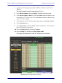
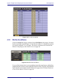
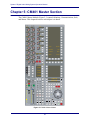
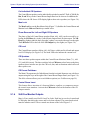
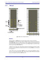
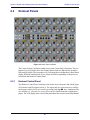
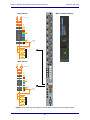
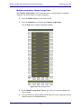
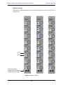
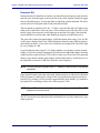
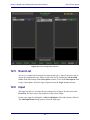
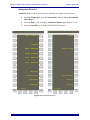
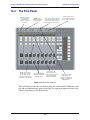
Figure 6-5 Bus Routing Panel
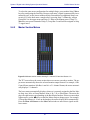
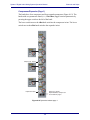
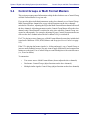
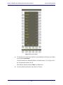
This panel shows the Group and Mix Bus routing for channels assigned to the Center
Strip. The Track Arming, Grp Route, Mix Route, and Grp Section switches along
the bottom of the panel determine the information being displayed and controlled.
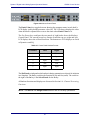
These switches intercancel: only one can be lit and active at a time. The Pan To: GRP
Busses and MIX Busses keys switch pan in/out for the Group and Mix Busses.
NOTE: The Reverse Route switch is not currently operational.
6.3.1
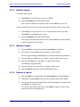
Grp Route
All 48 switches indicate Group Bus routing. The green number LEDs light to indicate
the available busses. The switches light to show that the Center Strip channel is routed
to that Group Bus.
6.3.2
Mix Route
All 48 switches indicate Mix Bus routing. The green number LEDs light to indicate the
available busses. The switches light to show that the Center Strip channel is routed to
that Mix Bus.
6.3.3
Grp Section
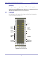
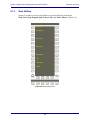
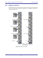
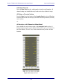
This is the default mode of operation. The top two rows indicate Group Bus routing.
The bottom row is used for the 16 Mix Busses.
6.3.4
Track Arming
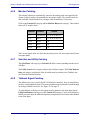
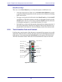
This mode allows track arming up to 48 tracks of a record machine.
88