1
Matrix Installation and Operation Instructions
5.0 INSTALLING GAS PIPING
5.1 Installation
Refer to the current National Fuel Gas Code ANSI
Z223.1/NFPA 54 or CAN/CGA B149.1 installation
codes, and local codes for gas piping requirements and
sizing.
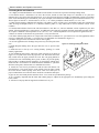
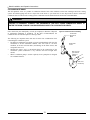
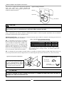
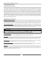
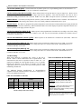
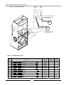
Figure 5.1 Gas Inlet Connection
It is highly recommended to use
flexible gas pipe, the gas valve and
blower cannot support the weight of
piping. If piping is used, ensure that
the valve supports NO WEIGHT
Pipe size running to the unit depends on:
o Length of pipe.
o Number of fittings.
o Type of gas.
o Maximum input requirement of all gas appliances
in the residence.
Gas cock shut
Off Valve to be
"T" type handle
Gas valve
Ensure that:
o Flexible gas pipe is used (if acceptable by local
codes). The gas valve and blower cannot support
the weight of piping, leading to blower vibration
and damaged components. If rigid piping is used,
ensure that the valve supports NO WEIGHT
o You plan the installation so that the piping does not
interfere with the vent pipe, or the removal of the valve, burner, and serviceable components.
o The Boiler shall be installed such that the gas ignition system components are protected from water (dripping, spraying, rain
etc.) during installation and servicing.
o The gas piping is large enough for all the appliances in the home. No appreciable drop in line or manifold pressure should
occur when any unit (or combination of units) lights or runs.
o Always use a pipe-threading compound that is resistant to propane (LP) gas solvent action. Use sparingly to all male threads,
starting at two threads from the end. Over doping or applying dope to the female end, can result in a blocked gas line.
DO NOT TIGHTEN FITTINGS WITHOUT SUPPORTING THE GAS VALVE as damage to the valve or motor can occur.
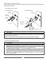
Install a manual “equipment Shut-Off Valve” as shown. Valve must be listed by a nationally recognized testing lab.
5.2 Testing and settings
Gas line and regulator(s) must be able to support a line pressure at the gas valve of 4-9”w.c for Natural Gas and 9-12”w.c for LP
while running at maximum rate. Matrix gas valves are equipped with two bleed ports to measure Line and Manifold pressure.
Note: Line pressure adjustments can only be made at the gas regulator, NOT AT THE GAS VALVE.
WARNING
IF LINE PRESSURE EXCEEDS ½ PSI (14 INCHES W.C.) COMPLETELY DISCONNECT LINE TO GAS VALVE.
THIS EXCESSIVE PRESSURE CAN DAMAGE VALVE, CAUSING A LEAK RESULTING IN FIRE OR
EXPLOSION.
14