1
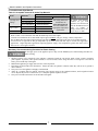
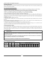
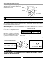
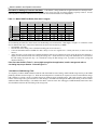
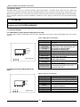
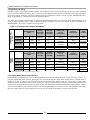
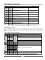
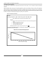
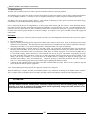
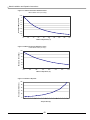
Matrix Installation and Operation Instructions
1.0 SPECIFICATIONS
Table 1.1 General Specifications
Model
CSA
Input
1,2
(MBH)
DOE
Heating
Capacity
1,3
(MBH)
136
136
Net
I=B=R
Rating
1,3
(MBH)
118
118
DOE
AFUE
3
(%)
Supply
Plenum
(inches)
Return
Plenum
(inches)
Airflow
Heating
(CFM)
Airflow
Cooling
(CFM)
Ventilation
(CFM)
Dimensions
H-W-D
(inches)
Vent/Air
4
Size
M100
25-150
95.1
22.5x18.5
18x18
400-1200 400-1600
53-28-38
3”
M100V
25-150
95.1
22.5x18.5
18x18
400-1200 400-1600
70-150
53-28-38
3”
Notes:
1 – Listed Input and Output ratings are at minimum vent lengths at Sea Level. Numbers will be lower with longer venting and/or altitudes greater then
2000 feet.
2 – The maximum output when operating on LP-Gas is limited to 145MBH.
3 – Based on rating plate input capacities, using standard test procedures prescribed by the U.S. Department of Energy. Ratings have been
confirmed by AHRI (GAMA).
4 – Matrix units require a special venting system, use only vent materials and methods detailed in these instructions.
In Canada:
De-rate by 5% for altitudes between 2000
and 4500 feet. For altitudes above 4500 feet
consult with local authorities.
Figure 1.1 Maximum Capacity vs. Altitude
160
150
Input (Mbh)
1.1 High Altitude Operation
The Matrix is designed to operate to capacity
in installations at 2000 feet of elevation or
less. As elevations higher than 2000 feet
have less dense air, the unit is not capable of
providing its specified capacity. (See Chart).
140
130
120
In USA:
De-rate by 4% for every 1000 feet over 2000
feet.
110
0-2000
3000
4000
5000
6000
7000
8000
9000
10000
Elevation (ft)
CAUTION
AT ELEVATIONS GREATER THAN 2000 FEET, THE COMBUSTION OF THE MATRIX MUST BE CHECKED
WITH A CALIBRATED COMBUSTION TESTER TO ENSURE SAFE AND RELIABLE OPERATION. CONSULT
SECTION 5.20 FOR INSTRUCTIONS ON ADJUSTING THE INPUT TO PROVIDE PROPER OPERATION.
IT IS THE INSTALLERS RESPONSIBILITY TO CHECK THE COMBUSTION, AND
TO ADJUST THE COMBUSTION IN ACCORDANCE TO SECTION 5.20
3