1
Instruction
Manual
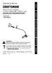
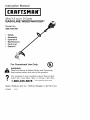
CRAFTSMfl
32cc/1.9 cu.in. 2-Cycle
GASOLINE WEEDWACKER
®
Model No.
358.795160
•
Safety
•
•
•
Assembly
Operation
Maintenance
•
Parts List
•
Espar_ol
For Occasional
Use Only
[UL)
V
WARNING:
Read and follow all Safety Rules and Operating
Instructions
before first use of this product.
For answers
Call
7 am-7
to your
questions or about
this pm,
product:
pm,
Mon.-Sat.,
10 am-7
Sun.
1-800-235-5878
Sears, Roebuck
530086199
8/22/01
and Co., Hoffman
_Ho0_0listed are Central
Estates,
Time)
IL 60179 U.S.A.
Warranty Statement
Safety Rules
Assembty
Operation
Maintenance
Service & Adjustments
2
2
4
5
9
10
Storage
TroubIeshooting
Table
Emissions Statement
Parts List
Spanish
Parts and Ordering
FULL TWO YEAR WARRANTY
ON CRAFTSMAN
WEEDWACKER
® LINE TRIMMER.
11
12
12
14
17
Back
_sGAS POWERED
For two years from the date of purchase, when this Craftsman Gas Powered
Weedwacker
Line Trimmer is maintained, lubricated, and tuned up according to
the operating and maintenance instructions in this manual, Sears will repair, free
of charge, any defect in materials or workmanship.
This warranty excludes nylon line, spark plug, and air filter, which are expendable
parts and become worn during normaI use.
If this Weedwacker tine trimmer is used for commerciaI purposes, this warranty applies for oniy 90 days from the date of purchase. If this Weedwacker line trimmer is
used for rental purposes, this warranty appties for only 30 days from the date of purchase.
This warranty applies oniy while this product is in use in the United States.
WARRANTY SERV}CE IS AVAILABLE BY RETURNING THE WEEDWACKER UNE TRIMMER
TO THE NEAREST SEARS STORE OR SERVICE CENTER IN THE UNtTED STATES
This warranty gives you specific legal rights, and you may aIso have other rights
which vary from state to state.
Sears, Roebuck and Co., D/817WA, Hoffman Estates, IL 60179
for line trimmer use only. Use of any
other accessories or attachments wiII
increase the risk of injury.
4_WARNING:
When using gardening appliances, basic safety precautions must always be followed to
reduce the risk of fire and serious
injury. Read and fotiow alt instructions.
This power unit can be dangerous[ Operator is responsible for following
instructions and warnings on unit and in
manual. Read entire instruction manual
before using unit! Be thoroughly famitiar
with the controls and the proper use of
the unit. Restrict the use of this unit to
persons who have read, understand,
and will follow the instructions and
warnings on the unit and in the manual
Never allow chitdren to operate this unit.
INSTRUCTION
MANUAL
'_
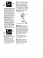
DANGER:
flailing devices.
_k WARNING:
Tdmmer line throws
objects violently. You and others can be
blinded/injured. Wear eye and leg
protection. Keep body parts clear of rotating line.
Eye Protection
_"
SAFETYINFORMATION
ONTHE UNIT
Boots
_)_
Keep children, bystanders, and animals
50 feet (15 meters) away. Stop unit immediately if approached.
Never use blades or
This unit is designed
2
Ifsituations
occur
which
arenotcov- • Make carburetor adjustments with
eredinthismanual,
usecareand
_ower end supported to prevent Iine
goodjudgment.
Ifyouneedassisfrom contacting any object.
tance,
contact
yourSears
Service
• Keep others away when making carCenter
orcal_
1-800-235-5878.
buretor adjustments.
OPERATOR
SAFETY
• Use only recommended
Craftsman
and replacement parts.
• Dress
properly.
Always
wear
safety • accessories
Have all maintenance and service
gtasses
orsimilar
eyeprotection
when
operating,
orperforming
main- not explained in this manua$ performed by a Sears Service Center.
tenance,
onyourunit(safety
g}asses
areavailable).
Eyeprotec- FUEL SAFETY
tionshoutd
bemarked
Z87.
and pour fueI outdoors.
• Always
wear
faceordustmaskifop- •• Mix
Keep away from sparks or flames.
eration
isdusty.
• Use a container approved for fuel
• Always
wear
heavy,
longpants,
tong • Do not smoke or allow smoking near
sleeves,
boots,
andgloves.
Wearing fue_ or the unit.
safety
tegguards
isrecommended. • Avoid spilling fue_ or oil, Wipe up aIt
• Always
wear
footprotection.
Donot
spi}ts.
gobarefoot
orwear
sandats.
Stay • fuet
Move at least "_0feet (3 meters)
clear
ofspinning
line.
from fueting site before start• Secure
hairabove
shoulder
_ength. away
ing engine.
Secure
orremove
loose
clothing
or
• Stop engine and allow to cool before
clothing
withtoosety
hanging
ties,
removing fuet cap.
straps,
tassels,
etc.Theycanbe
• Always store gasoline in a container
caught
inmoving
parts.
approved for flammable iiquids,
• Being
fullycovered
atsohetps
pro- CUTTING
SAFETY
tectyoufromdebris
andpieces
of
toxicplants
thrown
byspinning
line. ,I_, WARNING:
Inspect the area be• StayAlert.Donotoperate
thisunit fore each use. Remove
objects
when
youaretired,ill,upset
orun(rocks, broken glass, nails, wire, etc.)
dertheinfluence
ofalcohol,
drugs, which
can be thrown by or become
ormedication.
Watch
whatyouare entangled
in Sine. Hard objects can
doing;
usecommon
sense.
damage the trimmer head and be
• Wear
hearing
protection.
thrown causing serious injury.
• Never
startorruninside
aciosed
room
orbuilding.
Breathing
exhaust • Use onty for trimming, scaIping, mowfumes
cankitt.
ing and sweeping. Do not use for edg• Keep
handles
freeofoilandfuel.
ing, pruning or hedge trimming.
• Keep firm footing and baIance. Do not
UNIT
/ MAINTENANCE
SAFETY
overreach.
• Disconnect the spark ptug before
performing maintenance except carburetor adiustments.
• Look for and replace damaged or
toose parts before each use. Look
for and repair fuel leaks before use.
Keep in good working condition.
• Replace trimmer head parts that are
chipped, cracked, broken, or damaged in any other way before using
the unit.
• Maintain unit according to recommended procedures.
Keep cutting
tine at proper length.
• Use only Craftsman® replacement
tine. Never use wire, rope, string,
etc.
• Instant required shield propedy before
using the unit. Use only specified
trimmer head; make sure it is properly
instalIed and securety fastened.
• Make sure unit is assembled correctly as shown in this manual.
• Keep aH parts of your body away from
muffler and spinning line. Keep engine
below waist level. A hot muffler can
cause serious burns.
• Cut from your _eftto your right. Cutting
on right side of the shietd will throw debns away from the operator,
• Use on}y in daylight or good artificial
_ight.
• Use onty for jobs explained
in this
manual.
TRANSPORTING
AND STORAGE
• Allow engine to coo} before storing or
transporting in vehicle.
• Empty the fuel tank before storing or
transporting the unit. Use up fuet left in
the carburetor by starting the engine
and tetting it run until it stops.
• Store unit and fuet in area where fuel
vapors cannot reach sparks or open
flames from water heaters, electric
motors or switches, furnaces, etc.
• Store
unitsolinetimiter
blade
cannot closely
theirphysical
condition
and
ofthistool
accidentally
cause
injury.
Theunitcan thecondition
behungbythetube.
SPECIAL
NOTICE: This unit is
• Store
unitoutofreach
ofchildren. equipped with a temperature limiting
SAFETY
NOTICE:
Exposure
tovibra- muffler and spark arresting screen
tionsthrough
prolonged
useofgaso- which meets the requirements of Calilinepowered
handtoolscould
cause fornia Codes 4442 and 4443. All U.S.
btood
vessel
ornerve
damage
inthe
forest Iand and the states of California,
fingers,
hands,
andjoints
ofpeople
Idaho, Maine, Minnesota, New Jersey,
prone
tocirculation
disorders
orabOregon, and Washington require by
normal
swellings.
Prolonged
usein
Iaw that many internal combustion encoldweather
hasbeenlinked
toblood gines be equipped with a spark arrestvessel
damage
inotherwise
healthy ing screen. Ifyou operate in a locale
people.
Ifsymptoms
occur
suchas
where such regulations exist, you are
numbness,
pain,
tossofstrength,
Iegally responsible for maintaining the
change
inskincolor
ortexture,
ortoss operating condition of these parts.
Failure to do so is a violation of the
offeeling
inthefingers,
hands,
or
joints,
discontinue
theuseofthistool Iaw. For normal homeowner use, the
andseekmedical
attention.
Ananti- muffler and spark arresting screen wilt
vibration
system
doesnotguarantee not require any service. After 50
theavoidance
ofthese
problems.
Us- hours of use, we recommend that your
erswhooperate
power
toolsonacon- muffler be serviced or replaced by a
tinual
andregular
basis
must
monitor Sears Service Center.
CARTON
CONTENTS
Check carton contents against the following list.
Model 358.798160
• Trimmer
• Shield
• Wing Nut (screwed onto shield)
• Container of line
• Container of oil
Examine parts for damage. Do not
use damaged parts.
NOTE: If you need assistance or find
parts missing or damaged, call
1-800-235-5878.
It is normal for the fuel filter to rattle in
the empty fuel tank.
Finding fuel or oil residue on muffler is
normal due to carburetor adjustments
and testing done by the manufacturer.
ASSEMBLY
_IIWARNING:
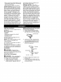
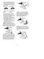
INSTALLATION
OF CUTTING HEAD
(if not already installed)
1. Push in locking lever and hold.
2. Rotate dust cup until the locking
lever fails into one of the grooves,
Locking Lever
3.
4.
If received as-
Cutting Heed
sembled, repeat all steps to ensure
your unit is properly assembled and all
fasteners are secure,
ADJUSTING
Continue to hold in locking lever.
This wilt keep the shaft from turning while tightening the hex nut.
Slide the trimmer head onto the
shaft of the gearbox.
_-
"_
Alignment
"_
THE HANDLE
Washer
Hex Nut _
_ WARNING:
When adjusting the
handle, be sure it remains between
the trigger and the safety decal.
1. Loosen wing nut on handle.
2. Rotate the handle on the tube to an
upright position; retighten wing nut.
5.
6.
Place the alignment washer over
the hex nut.
install alignment washer and hex
nut by threading nut onto the shaft
counterclockwise.
NOTE:
Itwiltbenecessary
tousea
deepsocket
totighten
thehexnut.
Thehexnutmust
becentered
inthe
hoIeofthecutting
headbefore
tightening.
7. Tighten
nutsecurely
(10-12
ft-lbs).
8. Release
Iocking
lever.
ATTACHING
SHIELD
,I_WARNING:
For proper orientation of shietd, see
KNOW YOUR TRIMMER illustration in OPERATION section.
1. Remove wing nut from shield.
2. Insert bracket into siot as shown.
3. Pivot shietd until bolt passes
through hote in bracket.
4. Securely tighten wing nut onto bott.
The shield must be
property installed. The shield provides
partiaI protection from the risk of thrown
objects to the operator and others and
is equipped with a line Iimiter blade
which cuts excess line to the proper
length, The Iine limiter blade (on underside of shield) is sharp and can cut you.
Shield
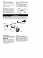
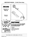
KNOW YOUR TRIMMER
READ THIS INSTRUCTION MANUAL AND SAFETY RULES BEFORE OPERATING YOUR
UNiT Compare the illustrations with your unit to familiarize yourseff with the location
of the various controls and adjustments. Save this manual for future reference.
Tube
%,
Trimmer
Head
"
e_a
d_
/
Line Limiter
Blade
_
ON/STOP Switch
r Handle
Throttle
Trigger
Muffler
ON/STOP SWITCH
The ON/STOP switch is used to stop the
engine. To stop the engine, push and
release the engine ON/STOP switch.
PRIMER BULB
The PRIMER BULB removes air from
the carburetor and fuel lines and fitis
them with fuel. This allows you to start
the engine with fewer pulls on the
starter rope. Activate the primer bulb
by pressing it and allowing it to return
to its original form.
CHOKE
The CHOKE helps to supply fuel to the
engine to aid in cold starting. Activate
the choke by moving the choke lever to
the FULL CHOKE position. After the engine attempts to start, move the choke
Iever to the HALF CHOKE position. Once
engine has started, move the choke lever to the OFF CHOKE position.
BEFORE
STARTING
ENGINE
WARNING:
the fuet information in the safety rules
before you begin. If you do not understand the safety rules, do not attempt
to fuel your unit. Call 1-800-235-5878.
FUELING
\\'_,L
_
ON/STOP
Be sure to read
Throttie Trigger
_X "_" "
\
HOW TO START YOUR UNIT
ENGINE
,I_ WARNING:
_[L WARNING:
Remove fuel cap
The tdmmer
head
slowly when refueling.
wilt turn while starting the engine.
Avoid any contact with the muffler. A
hot muffler can cause serious burns.
This engine is certified to operate on
unIeaded gasoline. Before operation,
gasotine must be mixed with a good
quaIity 2-cycIe air-cooIed engine oil.
We recommend Craftsman brand oit.
STARTING A COLD ENGINE (or a
warm engine after running out of
fuel)
Mix gasoline and oil at a ratio of 40:1
(A 40:1 ratio is obtained by mixing 3.2
ounces of oil with 1 gation of unleaded
gasotine). DO NOT USE automotive oil
or boat oil These oits will cause
engine damage.
When mixing fuel, follow instructions
printed on container.
Once oi_is added to gasoline, shake
container momentafiIy to assure that
the fuet is thoroughly mixed. Always
read and follow the safety rules
relating to fuel before fueting your unit.
IMPORTANT
Experience indicates that alcohol
Mended fuels (caIted gasohol or using
ethanol or methanoI) can attract moisture which leads to separation and
formation of acids during storage.
Acidic gas can damage the fuel system of an engine while in storage.
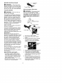
Position
Choke
. Lever
Primer Bulb
Muffler
1.
2.
3.
To avoid engine proMems, empty the
fuel system before storage for 30 days
or tonger. Drain the gas tank, start the
engine and let it run until the fueI tines
and carburetor are empty. Use fresh
fuel
next
Ar(ow ON
choke
lever
Choke
position
decaI
season,
Never use engine or carburetor cleaner products in the fuel tank or permanent damage may occur.
See the STORAGE section for additionaI information,
HOW TO STOP YOUR UNIT
• To stop the engine, push and retease the engine ON/STOP switch,
The switch will automatically return
to the ON position. Wait 5 seconds
before attempting to restart unit to
attow switch to reset.
• If engine does not stop, move choke
tever to FULL CHOKE position.
Set unit on a flat surface.
Stowly press the primer bulb 6
times.
Move choke lever to FULL CHOKE
by aligning arrow with position
shown on decal (see illustration
below).
4.
5.
6.
Squeeze the throttte trigger fuiIy and
hold through all remaining steps.
Puti starter rope handle sharply
until engine sounds as if it is trying
to start, but do not putt rope more
than 6 times.
As soon as engine sounds as if it
is trying to start, move choke lever
to HALF CHOKE by aiigning arrow
with position shown on decal (see
following illustration).
Choke
position
Arrow
on
-choke
lever
7. Pullstarter
rope
sharply
until
engine
runs,
butnomore
than6putls.
Ifthe
engine
doesn't
start
after
6pulls(at
the
HALF
CHOKE
position),
move
the
choke
lever
tothe
FULL
CHOKE
position
andpress
theprimer
butb
6
times.
Squeeze
andholdthethrottle
trigger
andputt
thestarter
rope
2
more
times.
Move
thechoke
tever
totheHALF
CHOKE
position
andpull
thestarter
ropeuntil
theengine
rdns,
butnomore
than6pulls,
tfthe
engine
doesn't
start,
repeat
procedure
2additional
times.
NOTE:
Ifengine
stilldoesn't
start,
it
isprobably
flooded.
Proceed
to
STARTING
AFLOODED
ENGINE
8. Once
theengine
starts,
allow
itto
run10seconds,
thenmove
the
choke
lever
toOFF
CHOKE
by
aligning
arrow
withposition
shown
ondecal(seeillustration
below).
Allow
theunittorunfor30more
seconds
atOFF
CHOKE
before
releasing
thethrottte
trigger.
NOTE:
tfengine
dieswiththechoke
lever
intheOFF
CHOKE
position,
move
thechoke
lever
totheHALF
CHOKE
position
andputtherope
untilengine
runs,butnomore
than
6pulls.
Arrow
on
choke
lever
Choke
position
decal
STARTING A WARM ENGINE
1. Move the choke _ever to the HALF
CHOKE position.
2. Squeeze and hold the throttle trigger. Keep throttte tdgger fully
squeezed until the engine runs
smoothly.
3. Pull starter rope sharply untit engine
runs, but no more than 5 putls.
4. Allow engine to run 15 seconds,
then move the choke tever to the
OFF CHOKE position.
NOTE: tf engine has not started, pu_t
starter rope 5 more pulls, tf engine still
does not run, it is probably flooded.
STARTING A FLOODED ENGINE
Flooded engines can be started by
placing the choke lever in the OFF
CHOKE position; then, pull the rope to
c_ear the engine of excess fuel. This
could require pulling the starter handle
many times depending on how badly
the unit is flooded.
If the unit still doesn't start, refer to
TROUBLESHOOTING TABLE or ca_I
1-800-235-5878.
OPERATING
ALWAYS
POSITION
WEAR:
Eye
PrOlection
Cut from your left to your right.
_WARNING:
Always wear eye
protection. Never lean over the trimmer
head. Rocks or debris can dcochet or
be thrown into eyes and face and
cause btindness or other serious injury.
Do not run the engine at a higher speed
than necessary. The cutting line will cut
efficiently when the engine is run at less
than futI throttle. At Iower speeds, there
is less engine noise and vibration.
Always release the throttle trigger and
allow the engine to return to idte
speed when not cutting.
To stop engine:
• Release the throttte trigger.
• Push and release the engine ON/
STOP switch.
CUTTING
_WARNING:
METHODS
Use minimum
speed and do not crowd the _ine when
cutting around hard objects (rock,
gravel, fence posts, etc,), which can
damage the trimmer head, become
entangled in the line, or be thrown
causing a serious hazard.
• Thetipofthelinedoes
thecutting.
Youwillachieve
thebestperformanceandminimum
linewearbynot
crowding
thelineintothecutting
area.
Therightandwrong
waysare
shown
below.
Tipoflinedoes
the Line
crowded
into
Right
Wrong
• The line witl easily remove grass
and weeds from around waits,
fences, trees and flower beds, but it
also can cut the tender bark of trees
or shrubs and scar fences.
• For trimming or scaIping, use less
than full throttle to increase line life
and decrease head wear, especially:
• During light duty cutting.
• Near objects around which the line
can wrap such as small posts,
trees or fence wire.
• For mowing or sweeping, use full
throttle for a good ctean job,
TRIMMING - Hold the bottom of the
trimmer head about 3 in. (8 cm) above
the ground and at an angle. Allow only
the tip of the tine to make contact. Do
not force trimmer tine into work area.
Trimming
Scalping
MOWING - Your trimmer is ideal for
mowing in places conventiona_ lawn
mowers cannot reach, tn the mowing
position, keep the line parallel to the
ground. Avoid pressing the head into
the ground as this can scaIp the
ground and damage the tool.
Mowing
SWEEPING - The fanning action of
the rotating line can be used to blow
away loose debris from an area. Keep
the line parallel to and above the area
surface and swing the toot from side
to side.
Sweeping
SCALPtNG - The scatping technique
removes unwanted vegetation down
to the ground. Hold the bottom of the
trimmer head about 3 in. (8 cm) above
the ground and at an angIe. Atlow the
tip of the line to strike the ground
around trees, posts, monuments, etc.
This technique increases line wear.
MAINTENANCE
SCHEDULE
WARNING:
Disconnect the spark plug before performing maintenance
except for carburetor adjustments.
CARE & MAINTENANCE TASK
WHEN TO PERFORM
Check for loose fasteners
Check for damaged
Before each use
and parts
Before each use
or worn parts
After each use
Inspect and clean unit and decals
Clean air filter
Inspect muffler and spark arresting
Replace
Every 5 hours of operation
screen
spark plug
Every 50 hours of operation
"Yearly
G EN ERAL R ECOMMENDATIONS
The warranty on this unit does not
cover items that have been subjected
to operator abuse or negligence. To
receive full value from the warranty,
the operator must maintain unit as
instructed in this manual. Various adjustments wilt need to be made periodically to properly maintain your unit.
CHECK FOR LOOSE
FASTENERS AND PARTS
• Spark Plug Boot
• Air Fiiter
• Housing Screws
• Assist Handle Screw
• Debris Shield
CHECK FOR DAMAGED OR
WORN PARTS
Contact Sears Service Center for replacement of damaged or worn parts.
• ON/STOP Switch - Ensure ON/STOP
switch functions properly by pushing
and releasing the switch. Make sure
engine stops. Wait 5 seconds before attempting to restart unit to allow switch to reset. Restart engine
and continue
• Fuel Tank - Discontinue use of unit
if fuel tank shows signs of damage
or leaks.
• Debris Shield - Discontinue use of
unit if debris shield is damaged.
INSPECT AND CLEAN UNIT AND DECALS
• After each use, inspect complete
unit for loose or damaged parts.
Clean the unit and decals using a
damp cloth with a mitd detergent.
• Wipe off unit with a cIean dry cloth.
CLEAN AIR FILTER
A dirty air filter decreases engine performance and increases fuel consumption and harmful emissions. Always clean after every 5 hours of
operation.
1. Clean the cover and the area
around it to keep dirt from failing
into the carburetor chamber when
the cover is removed.
2. Remove parts by pressing button
to release air filter cover.
NOTE: To avoid creating a fire hazard
or producing harmful evaporative
emissions, do not clean filter in gasoline or other flammable solvent.
3. Wash the filter in soap and water.
4. Allow filter to dry.
5. Add a few drops of oil to the filter;
squeeze the filter to distribute oil.
6. Replace parts.
_-_ A F e
Button
_f....
-_
REPLACE
SPARK
PLUG
Reptace the spark plug each year to
ensure the engine starts easier and
runs better. Set spark plug gap at
0.025 in. Ignition timing is fixed and
nonadjustable.
1. Twist, then pull off spark plug boot.
2. Remove spark plug from cylinder
and discard.
3. Replace with Champion RCJ-8Y
spark plug and tighten with a 3/4
in. socket wrench (10-12 ft.-tbs).
4. Reinstall the spark plug boot.
9
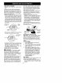
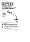
LINE REPLACEMENT
• Always use Craftsman replacement
tine.
Choose the line size best suited for
the job at hand. Green colored line is
designed for cutting grass, red line for
grass and small weeds. The black cotored tine is designed for cutting larger
weeds and light brush.
• Before inserting the line into the holes
in the cutting head, identify the proper
holes, When using Green, or Red, insert line into the holes marked small
on the cutting head. Black line should
be inserted in the holes marked large.
• Insert both ends of your line through
the proper holes in the side of the cutting head,
TPositioning
Small
Old fuel, a dirty air filter, a dirty fuel filter, or flooding may give the impression of an improperly adjusted carburetor. Check these conditions before
adjusting the carburetor.
The carburetor has been carefully set
at the factory. Adjustments may be
necessary if you notice any of the following conditions:
• Engine wilt not idle. See IDLE
SPEED-T under adjusting procedure.
• Engine dies or hesitates instead of
accelerating. See ACCELERATION
CHECK under adjusting procedure.
• Loss of cutting power. See MIXTURE
ADJUSTMENT (L or H) under adjusting procedure.
There are two adjustment screws on
the carburetor, a mixture screw and an
idle speed screw.
lie Speed
Screw
• Insert ends of the line one at a time
through the positioning tunnels.
Line against
• Pull the line and make sure the tine is
against the hub and extended fully
through the positioning tunnels.
• Correctly
installed tine witl be the
same length on both ends.
CARBURETOR
ADJUSTMENT
_
WARNING:
The trimmer head
witt be spinning during most of this
procedure. Wear your protective
equipment and observe all safety precautions. After making mixture adjustments, recheck idle speed.
Carburetor adjustment is critical and if
done improperly can permanently
damage the engine as welt as the carburetor, tf you require further assistance or are unsure about performing
this procedure, caIt our customer assistance help tine at 1-800-235-5878.
(with Umiter
Air Filter
Cap)
ADJUSTING
PROCEDURE
CAUTION:
Do not force plastic limiter
caps on screws beyond the built-in
stops or damage will occur. Be sure
trimmer line is extended to the maximum length allowed by the line limiter
blade.
Initial Settings:
1. Turn mixture screw counterclockwise until it stops.
2. Turn the idle speed screw clockwise
until it stops. Now turn counterclockwise 4 1/2 turns.
3. Start engine, cut grass for 3 minutes, then proceed to adjust screws
according to the instructions below.
tf engine performance at initial settings is acceptable, no further adjustments are necessary. If engine
does not start, refer to TROUBLESHOOTING TABLE. If still unable to
remedy situation, calt
1-800-235-5878.
Idle Speed
Allow engine to idle, Adjust speed until
engine runs without stalling.
• Turn idle speed screw clockwise to increase engine speed if engine stalls
or dies.
10
• Turn idle speed screw counterclockwise to decrease engine speed.
No further adjustments are necessary
if performance is satisfactory.
Mixture Adjustment
CAUTION:
Do not operate engine at
full throttle for prolonged periods while
making adjustments as damage to the
engine can occur. Adjust the mixture
screw 1/16 of a turn at a time. A 1/t6
turn is about the width of the slot in the
top of the screw.
• Turn the mixture screw clockwise until
the engine has good power w_th no
WARNING:
Perform the following steps after each use:
• Allow engine to cool before storing
or transporting.
• Store unit and fuel in a well ventilated area where fuel vapors cannot
reach sparks or open flames from
water heaters, electric motors or
switches, furnaces, etc.
• Store unit with all guards in place.
Position unit so that any sharp object cannot accidenta;ly cause injury.
• Store unit and fuel well out of the
reach of children.
SEASONAL
STORAGE
Prepare unit for storage at end of season or if it wilt not be used for 30 days
or more.
If your unit is to be stored for a period
of time:
• Clean the entire unit before lengthy
storage.
• Store in a clean dry area.
• Lightly oil external meta_ surfaces.
FUEL SYSTEM
Under FUELING ENGINE in the OPERATION section of this manual, see message Iabeted IMPORTANT
regarding
the use of gasohot in your engine.
Fuel stabilizer is an acceptable aIter-
hesitation while cutting. Do not adjust
by sound or speed, but judge by how
well the engine performs while cutting.
• Turn the mixture screw counterclockwise if the engine has speed but dies
or lacks power while cutting.
After completing adjustments, check
for acceleration. Reset if necessary.
Acceleration
Check
If engine dies or hesitates instead of
accelerating, turn the mixture screw
counterclockwise
until you have
smooth acceleration.
native in minimizing the formation of
fuel gum deposits during storage. Add
stabilizer to the gasoline in the fuel
tank or fuel storage container. FolIow
the mix instructions found on stabilizer
container. Run engine at least 5 minutes after adding stabilizer.
Craftsman 40:1,2-cycle
engine oil (air
cooled) is already btended with fuel
stabilizer, tf you do not use this Sears
oil, you can add a fuel stabilizer to
your fuel tank.
ENGINE
• Remove spark plug and pour 1 teaspoon of 40:1,2-cycle
engine oit (air
cooled) through the spark plug
opening. Slowly pull the starter rope
8 to 10 times to distribute oil.
• Replace spark plug with new one of
recommended
type and heat range.
• Clean air filter.
• Check entire unit for loose screws,
nuts, and bolts. Replace any damaged, broken, or worn parts.
• At the beginning of the next season,
use only fresh fuel having the proper
gasoline to oil ratio.
OTHER
• Do not store gasoline from one season to another.
• Replace your gasoline can if it starts
to rust.
11
TROUBLESHOOTING
TABLE
WARNING:
Atways stop unit and disconnect spark plug before performing all of the recommended
remedies below except remedies that require
operation
TROUBLE
Engine will not
start.
of the unit.
CAUSE
1. Engine flooded
2 Fuel tank empty.
3. Spark plug not firing.
4. Fuel not reaching
carburetor.
5. Carburetor requires
adjustment.
REMEDY
1. See "Starting a Flooded Engine" in
Operation Section.
2. FilI tank with correct fuel mixture.
3. Install new spark plug
4. Check for dirty fuel filter; replace.
Check for kinked or split fuel line;
repair or replace.
5. See "Carburetor Adjustment '_in
Service and Adjustments Section
Engine will
not idle
properly
1. Carburetor requires
adjustment.
2 Crankshaft seals worn.
3. Compression
low.
t
Engine witl not
accelerate,
lacks power,
or dies under
a load
1. Air filter dirty
2 Spark plug fouled
t. Clean or replace air filter
2 Clean or replace plug
and regap.
3 See "Carburetor Adjustment"
in
Service and Adjustments Section.
4 Contact Sears Service Center.
Engine
smokes
excessively,
1. Choke partially on
2 Fuel mixture incorrect
3. Carburetor requires
adjustment.
4. Carbon build-up on
muffler outlet screen.
5. Compression
low.
3. Air filter dirty.
4. Carburetor requires
adjustment.
Engine runs
hot
t. Fuel mixture incorrect.
2. Spark pIug incorrect
3. Carburetor requires
adjustment
4. Carbon build-up on
muffler outlet screen
YOUR WARRANTY RIGHTS AND
OBLIGATIONS:
The U. S. Environmental Protection Agency and Sears,
Roebuck and Co., U.S.A., are pieased
to explain the emissions control system warranty on your lawn and garden
equipment engine. Ait new utility and
Iawn and garden equipment engines
must be designed, built, and equipped
to meet the stringent anti-smog standards, Sears must warrant the emission control system on your lawn and
garden equipment engine for the periods of time ]isted below provided there
has been no abuse, neglect, or improper maintenance of your lawn and
garden equipment engine. Your emission control system includes parts
See "Carburetor Adjustment"
in
Service and Adjustments Section.
2. Contact Sears Service Center.
3 Contact Sears Service Center.
5 Contact
Sears Service
Center.
1. Adjust choke.
2. Empty fuel tank and refiII with
correct fue_ mixture.
3. Clean or replaceair filter.
4. See "Carburetor
Adjustment" in
Service and Adjustments Section
1. See "Fueling Engine" in Operation
section.
2. Replace with correct spark plug.
3. See 'Carburetor
Adjustment" in
Service and Adjustments Section
4. Contact Sears Service Center.
such as the carburetor and the ignition
system. Where a warrantable condition exits, Sears will repair your Iawn
and garden equipment engine at no
cost to you. Expenses covered under
warranty include diagnosis, parts and
labor, MANUFACTURER'S
WARRANTY COVERAGE:
if any emissions related part on your engine (as
]isted under Emissions Control Warranty Parts List) is defective or a defect in the materials or workmanship of
the engine causes the faiiure of such
an emission related part, the part wi]I
be repaired or replaced by Sears,
OWNER'S WARRANTY
RESPONSIBILITIES: As the lawn and garden
equipment engine owner, you are re12
sponsible
fortheperformance
ofthe
required
maintenance
listed
inyour
instruction
manual
Sears
recommends
thatyouretain
attreceipts
coveringmaintenance
onyourIawn
and
garden
equipment
engine,
butSears
cannot
deny
warranty
soIeIy
forthe
Iackofreceipts
orforyourfailure
to
ensure
theperformance
ofaitscheduledmaintenance.
Asthelawnand
garden
equipment engine owner, you
shoutd be aware that Sears may deny
you warranty coverage if your tawn
and garden equipment engine or a
part of it has failed due to abuse, neglect, improper maintenance, unapproved modifications, or the use of
parts not made or approved by the
original equipment manufacturer.
You
are responsible for presenting your
tawn and garden equipment engine to
a Sears authorized repair center as
soon as a problem exists. Warranty
repairs should be completed in a reasonable amount of time, not to exceed
30 days. tf you have any questions
regarding your warranty rights and responsibilities, you should contact your
nearest authorized service center or
catt Sears at 1-800-469-4663.
WARRANTY COMMENCEMENT
DATE:
The warranty period begins on the
date the lawn and garden equipment
engine is purchased.
LENGTH OF
COVERAGE:
This warranty shaI{ be
for a period of two years from the initial date of purchase. WHAT IS COVERED: REPAIR OR REPLACEMENT
OF PARTS. Repair or replacement of
any warranted part witl be performed
at no charge to the owner at an approved Sears servicing center. If you
have any questions regarding your
warranty rights and responsibilities,
you should contact your nearest authorized service center or catt Sears at
1-800-469-4663.
WARRANTY PERIOD: Any warranted part which is not
scheduled for replacement as required maintenance, or which is
scheduled only for regular inspection
to the effect of "repair or replace as
necessary" shall be warranted for 2
years. Any warranted part which is
scheduled for replacement as required maintenance shalt be warranted for the period of time up to the
first scheduled replacement point for
that part, DIAGNOSIS: The owner
shall not be charged for diagnostic tabor which leads to the determination
that a warranted part is defective if the
diagnostic work is performed at an approved Sears servicing center. CONSEQUENTIAL
DAMAGES: Sears
may be liable for damages to other
engine components caused by the
failure of a warranted part still under
warranty. WHAT IS NOT COVERED:
All faitures caused by abuse, neglect,
or improper maintenance are not covered. ADD-ON OR MODIFIED
PARTS: The use of add-on or modified
parts can be grounds for disallowing a
warranty claim. Sears is not tiabte to
cover failures of warranted parts
caused by the use of add-on or modified parts. HOW TO FILE A CLAIM: If
you have any questions regarding
your warranty rights and responsibilities, you should contact your nearest
authorized service center or caIt Sears
at 1-800-469-4663.
WHERE TO GET
WARRANTY
SERVICE: Warranty services or repairs shall be provided at all
Sears service centers, cat{:
1-800-489-4663.
MAINTENANCE,
REPLACEMENT AND REPAIR OF
EMISSION RELATED PARTS: Any
Sears approved replacement part
used in the performance of any warranty maintenance or repair on emission related parts wilt be provided
without charge to the owner if the part
is under warranty. EMISSION CONTROL WARRANTY
PARTS LIST:
Carburetor, Ignition System: Spark
Plug (covered up to maintenance
schedule), Ignition Module. MAINTENANCE STATEMENT: The owner is
responsible for the performance of all
required maintenance as defined in
the instruction manual,
13