1
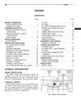
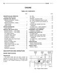
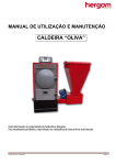
9 - 64
ENGINE
NS/GS
REMOVAL AND INSTALLATION (Continued)
Fig. 60 Oil Pump Drive Gear
Fig. 61 Oil Pressure Relief Valve
INSTALLATION
(1) Install new O-ring and lubricate with clean
engine oil.
(2) Install oil pump and tighten retaining screws
to 27.5 N·m (240 in. lbs.).
(3) Install oil pump drive gear on crankshaft.
(4) Install front cover. Refer to Timing Chain
Cover Installation in this section.
(5) Install pump shaft support bracket assembly.
INSTALLATION
(1) Thoroughly clean all components and relief
valve pocket in cylinder block.
(2) Fit plunger, spring and cap into block.
(3) Compress spring and install retaining clip.
Ensure clip is completely seated in groove.
CAUTION: Correct torque on the vibration damper
nut is important or engine damage can occur.
(6) Install vibration damper. Torque nut to 441
N·m (325 ft. lbs.)
(7) Install both accessory drive belts. Refer to
Group 7, Cooling.
(8) Install right splash shield.
OIL PUMP PRESSURE RELIEF VALVE
REMOVAL
(1) Remove oil pan.
(2) Remove clip retaining relief valve.
(3) Remove relief valve cap, spring, and plunger
(Fig. 61).
(4) Check relief valve spring length. Relief valve
spring free length is 57.5mm (2.263 in.). If spring
length is less or spring is distorted it must be
replaced.
(5) Check plunger for scoring, replace if necessary.
OIL FILTER ADAPTER AND OIL COOLER
REMOVAL
(1) Remove oil filter.
(2) Remove oil cooler adapter bolt.
(3) Remove oil cooler (Fig. 62).
INSTALLATION
(1) Install oil cooler with new gasket, tighten oil
cooler adapter bolt to 60 N·m (44 ft. lbs.).
(2) Install oil filter adapter to oil cooler and
tighten to 49 N·m (36. lbs.).
(3) Install oil filter and tighten to 9.8 N·m (85 in.
lbs.) and add oil.
VACUUM PUMP
REMOVAL
(1) Disconnect the battery cable.
(2) Raise vehicle on hoist.
(3) Remove right splash shield (Fig. 63).
(4) Remove accessary drive belts. Refer to Group 7,
Cooling.
(5) Remove vibration damper nut.
NOTE: Crankshaft
thread.
damper
nut
is
left
handed