1
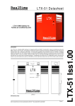
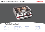
LTX-VCI Datasheet
Description
The RealTime LTX-VCI extends RealTime air-conditioning control solutions by providing a compatible interface to a
range of air-conditioning manufacturers. The LTX-VCI acts as virtual interface that allows the existing range of
RealTime air-conditioning BMS interfaces and LonWorks Controllers to be instantly compatible with additional airconditioning manufacturers products.
The VCI provides the necessary functionality to control individual A/C units as well as return fault and temperature
readback data from each unit in a format compatible with existing RealTime BMS control solutions. The VCI can
handle manufacturer interfaces with up to 64 units.
144.00
37.00
Power LED
LTX
Service Pin
SERVICE
Service LED
134.00
Dimensions (mm)
RealTime Control Systems Ltd. Park House, Greenhill Crescent, Watford WD18 8PH. Tel 01923 233384 Fax 01923 233385
Web: www.realtime-controls.co.uk, E-mail: [email protected]
LTX-VCI Datasheet Issue 1.05.01 12/07/2003 Doc No. 92101
Page 1
LTX-VCI Iss1.05
LTX-VCI
Virtual Control Interface
LTX-VCI Datasheet
1 Introduction
1.1
•
•
•
•
•
1.2
LTX-VCI Features
Provides a common control interface for many of the major brands of package Airconditioning units
Simplifies the monitoring and control of large numbers of A/C units
Allows the monitoring and control of air-conditioning units from range of conventional and
LonWorks Building Management Systems
Provides backwards compatibility with existing RealTime BMS controllers and interfaces
Provides a practical interface for managing thousands of network variables without the
need for large numbers of bindings, and the ability to rezone the system without rebinding
Description
The following table provides the range of existing coverage for RealTime controllers and
shows which solutions at present require the addition of the VCI. The range of solutions is
constantly expanding, the latest solutions are available from the RealTime web site.
BMS
LonWorks
Manufacturer
Interface
Trend
LTX-21
Cylon
LTX-51
Andover
LTX-51
RealTime
LTX-SC
LTX-VCI Interface Required
Native A/C Interface
Air-Conditioning Manufacturer
Toshiba
Daikin Mitsubishi
ä
ä
ä
ä
LG1
ä
ä
ä
ä
YES
L-Gateway
ä
ä
ä
ä
YES
LMAP
The LTX-VCI can handle A/C interfaces with up to 64 indoor units. Many LTX controllers are
only designed to handle 16 units, therefore the VCI can serve data to up to 4 LTX controllers in
order to allow access and control of all units.
Interfaces that the LTX-VCI are compatible with are associated with a Device Interface Sheet
within this datasheet that describes specific details of interfacing, lists what functionality is
available and provides fault code references. The current version of the LTX-VCI is compatible
with the following device interfaces:
Manufacturer
Daikin
Mitsubishi
Mitsubishi
Product
L-Gateway DCS601A1R
LMAP02-E
LMAP03-E
Device Interface Sheet
page 5
page 7
page 9
RealTime Control Systems Ltd. Park House, Greenhill Crescent, Watford WD18 8PH. Tel 01923 233384 Fax 01923 233385
Web: www.realtime-controls.co.uk, E-mail: [email protected]
LTX-VCI Datasheet Issue 1.05.01 12/07/2003 Doc No. 92101
Page 2
LTX-VCI Iss1.05
The LTX-VCI expands RealTime air-conditioning controls functionality to allow interfacing with
a range of air-conditioning manufacturers. The LTX-VCI acts as virtual interface that allows the
existing range of RealTime air-conditioning BMS interfaces and LonWorks Controllers to be
instantly compatible with additional air-conditioning manufacturers products.
LTX-VCI Datasheet
1.3
Engineering
Engineering is a two step process, on one side connecting the VCI with the air-conditioning
Interface, on the other connecting the BMS control system via a suitable LTX controller.
To engineer a specific system, follow the instructions in this datasheet to set up the linkage to
the BMS interface and perform general configuration of the LTX-VCI. Refer to the relevant
Device Interface Sheet within this datasheet for the relevant manufacturers product, this will
provide product specific details of the available functionality and specific configuration
information. Device Interfaces Sheets are specific to the LonWorks Program ID of the
interface. If the program ID is different from that in the Device Interface Sheet then contact
RealTime as there may be compatibility issues.
The system must be engineered by a suitably trained LonWorks integrator using the correct
engineering tools. Engineers new to engineering RealTime products should contact us for
additional information. The LonWorks functional profile for the VCI is available at the rear of
this datasheet.
Air-Conditioning Interface
Note: Before the system is installed it is advisable to establish the unit addressing
methodology being used in the system. As a general principle it is recommended that
units are addressed from unit ‘1’ (the lowest possible address) upwards with no gaps in
the addressing scheme. Schemes that start the addressing at higher values and have
gaps in the addressing scheme are liable to create problems in the interfacing and
control of the system.
Firstly consult the Device Interface Sheet relevant to the system being installed, these are
found in this datasheet. The device interface sheet will provide device specific information on
the device functionality and any special steps that need to be taken during installation and
engineering. The Device Interface Sheet provides the relevant VCI Mode Number for the
device in question, this value configures the VCI to the correct configuration for the selected
interface. The first task in configuring the VCI is set this value in the Node: UCPTVCIMode. If
unsure of the value, setting Node: UCPTVCIMode equal to 0 disables any communication with
the interface. WARNING: Using an incorrect value for UCPTVCIMode can lead to
unpredictable behaviour of the system.
Once the VCI Mode is selected the VCI will be configured to the maximum number of indoor
units for the selected interface, should the actual number of units be less than the maximum
this it is possible to restrict the overall range of units addressed by the VCI by using the
configuration parameters Node:UCPTMinUnitNum and Node:UCPTMaxUnitNum This will
reduce the amount of time required to scan the system in order to produce faster updates of
readback data and will also prevent invalid unit addresses from being processed.
To enable communication between the VCI and the A/C Interface create a single message tag
binding between the tag VCItag on the VCI and the standard msg_in tag on the selected A/C
1
interface using a suitable LonWorks engineering tool.
The VCI should now be communicating with the air-conditioning interface, polling data from the
selected range of units. The VCI will not write any data to the units until it receives control data
from the BMS interface.
1
Message tags in LonMaker for Windows are found on the Virtual Function Block (VFB) of each of the devices. If adding by hand it will
be necessary to drop the VCItag msg_out object onto the VCI VFB and a msg_in object on the a/c interface VFB to make them visible.
Connecting them as normal will bind the tags.
RealTime Control Systems Ltd. Park House, Greenhill Crescent, Watford WD18 8PH. Tel 01923 233384 Fax 01923 233385
Web: www.realtime-controls.co.uk, E-mail: [email protected]
LTX-VCI Datasheet Issue 1.05.01 12/07/2003 Doc No. 92101
Page 3
LTX-VCI Iss1.05
1.3.1
LTX-VCI Datasheet
1.3.2
BMS Interface
The VCI consists of four VCI Proxy function blocks that manage data exchange between one
or more BMS interfaces and the A/C interface. Each proxy can be bound to a different LTX
controller in order to allow the control of up to 64 units. In the default configuration the main
proxy, VCI Proxy[0] can be used to directly address up to 64 A/C units. The remaining three
proxies VCI Proxy[1] to VCI Proxy[3] each address 16 consecutive units. The following are the
default address ranges of the units
Function Block
VCI Proxy[0]
VCI Proxy[1]
VCI Proxy[2]
VCI Proxy[3]
Start Unit
1
17
33
49
End Unit
64
32
48
64
If it is necessary to use more than one interface then each interface is bound to successive
VCI Proxies. For example a second LTX interface would be bound to VCI Proxy[1], this
performs a default mapping so that unit 1 in the second LTX corresponds to unit number 17 in
the VCI and unit 16 in the second LTX corresponds to unit number 32 in the VCI.
Each of the proxy function blocks has two configuration parameters UCPTStartUnitOffset and
UCPTEndUnitOffset which can be used to map each proxy to any address range within the
range 1 to 64. If the configuration parameters are set to zero the function block will operate
with default address ranges outline above. These offset values can be used to map units into
the correct address range should a site addressing scheme not begin at 1.
1.3.3
Fault Code Mapping
Existing LTX controllers use an established fault reporting system that allows fault codes to be
translated and reported in various different BMS architectures. To retain backwards
compatibility the current version of the VCI translates manufacturers fault codes into the
established fault code format. In the BMS the LTX can be translated back into the native
manufacturers codes either manually or using suitable lookup mechanisms. Each Device
Interface Sheet provides the necessary translation between LTX and manufacturers fault
codes.
RealTime Control Systems Ltd. Park House, Greenhill Crescent, Watford WD18 8PH. Tel 01923 233384 Fax 01923 233385
Web: www.realtime-controls.co.uk, E-mail: [email protected]
LTX-VCI Datasheet Issue 1.05.01 12/07/2003 Doc No. 92101
Page 4
LTX-VCI Iss1.05
In the simplest configuration a single LTX controller is bound to VCI Proxy[0] and can monitor
and control units in the range 1 to the maximum unit count for the LTX controller. Typically this
is to a limit of 16 units, but some new LTX controllers may be able to address up to 64 units.
LTX-VCI Datasheet
Device Interface Sheet: Daikin L-Gateway DCS601A1R
Manufacturer
Device Name
Product Code
Program ID
Indoor Units
VCI Mode Number
LTX-VCI compatibility
Daikin
L-Gateway Prototype
DCS601A1R
90:00:87:48:50:04:04:02
64
10
v0.90 or greater
Control Function
Setpoint
Fanspeed
Run Mode
Louver
On/Off
Central/Local
Control
Readback Function
Return air
temperature
Heat-exchanger
temperature
Fault Code
Comments
Range restrictions may be applied by LTX interfaces
Only low or high speed available. Fanspeed settings of AUTO,
LOW and MEDIUM are treated as LOW, HIGH is treated as
HIGH
HEAT, COOL, AUTO and FAN_ONLY available
Not available on L-Gateway.
Standard behaviour
L-Gateway allows separate switching of On/Off, Setpoint and
Mode switches. The LTX-VCI will switch all as a single global
setting of Central or Local.
Comments
Available in L-Gateway
Not available
Louver
On/Off
Selected Daikin fault codes are mapped into the LTX – see
fault code reference table
Setpoint readback will indicate the actual unit setpoint, this
may be offset by the unit from the demand setpoint
Readback will return either LOW or HIGH
Run mode readback will indicate actual operating mode, during
AUTO operation readback will indicate actual mode (COOL,
HEAT etc)
Not available
Standard
Additional Functions
Fault Reset
Filter Reset
Comments
Not Available
Available if implemented on LTX BMS controller
Setpoint
Fanspeed
Run Mode
Configuration Notes
No specific configuration requirements.
RealTime Control Systems Ltd. Park House, Greenhill Crescent, Watford WD18 8PH. Tel 01923 233384 Fax 01923 233385
Web: www.realtime-controls.co.uk, E-mail: [email protected]
LTX-VCI Datasheet Issue 1.05.01 12/07/2003 Doc No. 92101
Page 5
LTX-VCI Iss1.05
Interface Functionality
LTX-VCI Datasheet
Operation Notes
Master/Slave Operation
Some Daikin A/C units operate in AUTO with separate heating and cooling setpoints. The
readback values of run-mode and setpoint reflect the actual values the unit is operating to
rather than those initially set by the BMS or keypad. With the LTX Master/Slave operation the
LTX controllers copy the read-back data from the keypad master and write it into the slave
units. If the master unit is operating in AUTO with an initial setpoint of 20 degrees then when it
moves into heating mode the readback data will be 18 degrees, HEAT, and the slave units will
be placed in this state. Hence the slave units will mirror the operation of the master as
expected and will perform the same setpoint transitions as the master even though they will
not be operating in AUTO. It is recommended that the system designer should check that this
functionality is acceptable.
Fault Mapping
LTX-VCI Code
Decimal
Hex
21
22
23
24
25
26
27
28
29
30
31
32
33
34
35
36
37
38
39
40
41
42
43
44
45
15
16
17
18
19
1A
1B
1C
1D
1E
1F
20
21
22
23
24
25
26
27
28
29
2A
2B
2C
2D
Daikin Fault Code
A0
A1
A3
A6
A7
A9
AF
AJ
C4
C5
C9
CJ
E0
E1
E3
E4
E9
F3
H9
J3
J5
J6
JA
JC
JH
LTX-VCI Code
Decimal
Hex
46
47
48
49
50
51
52
53
54
55
56
57
58
59
60
61
62
63
64
101
111
112
153
255
2E
2F
30
31
32
33
34
35
36
37
38
39
3A
3B
3C
3D
3E
3F
40
65
6F
70
99
FF
RealTime Control Systems Ltd. Park House, Greenhill Crescent, Watford WD18 8PH. Tel 01923 233384 Fax 01923 233385
Web: www.realtime-controls.co.uk, E-mail: [email protected]
LTX-VCI Datasheet Issue 1.05.01 12/07/2003 Doc No. 92101
Daikin Fault Code
L4
L5
L8
L9
LC
P1
P4
U0
U1
U2
U4
U5
U7
U8
U9
UA
UC
UF
UH
Unknown Fault Code
AC Non-Existance
AC Comms Error
LTX Query Fail
No fault
Page 6
LTX-VCI Iss1.05
The following mapping provides a list of the Daikin fault codes that are reported individually
and the corresponding single byte codes that the VCI generates for these codes. In some
control systems the VCI code will be visible and manual translation will have to performed, in
others the supervisor software can be used to automatically map the VCI code to the original
Daikin fault code so the native codes can be presented. Future versions of LTX controllers will
allow the original codes to be reported directly.
LTX-VCI Datasheet
Device Interface Sheet: Mitsubishi LMAP02-E
Manufacturer
Device Name
Product Code
Program ID
Indoor Units
VCI Mode Number
LTX-VCI compatibility
Mitsubishi
LMAP
LMAP02-E
90:00:71:00:76:00:02:02
50
20
V1.00 or greater
Control Function
Setpoint
Fanspeed
Run Mode
Louver
On/Off
Central/Local
Control
Readback Function
Return air
temperature
Heat-exchanger
temperature
Fault Code
Comments
Range restrictions may be applied by LTX interfaces
LTX Mappings of 0 = LOW, 1 = MID2, 2 = MID1, 3=HIGH
Consult LMAP datasheet for mappings for units with fewer fan
speeds.
HEAT, COOL, AUTO and FAN_ONLY available
Not available
Standard behaviour
LMAP allows separate switching of On/Off, Setpoint and Mode
switches. The LTX-VCI will switch all as a single global setting
of Central or Local.
Comments
Available
Not available
Setpoint
Fanspeed
Run Mode
Louver
On/Off
The LMAP02 only supplies Fault/No Fault indication, for
comprehensive fault code reporting it is necessary to use the
LMAP03
Available
Available
Available
Not available
Available
Additional Functions
Fault Reset
Filter Reset
Comments
Not Available
Not Available?
Configuration Notes
1) To use keypad lockout (prohibit) functionality, SW1-1 on the LMAP must be ‘ON’.
Fault Mapping
RealTime Control Systems Ltd. Park House, Greenhill Crescent, Watford WD18 8PH. Tel 01923 233384 Fax 01923 233385
Web: www.realtime-controls.co.uk, E-mail: [email protected]
LTX-VCI Datasheet Issue 1.05.01 12/07/2003 Doc No. 92101
Page 7
LTX-VCI Iss1.05
Interface Functionality
LTX-VCI Datasheet
The following mapping provides a list of the Mitsubishi fault codes that are reported individually
and the corresponding single byte codes that the VCI generates for these codes. In some
control systems the VCI code will be visible and manual translation will have to performed, in
others the supervisor software can be used to automatically map the VCI code to the original
Mitsubishi fault code so the native codes can be presented. Future versions of LTX controllers
will allow the original codes to be reported directly.
Note that the Mitsubishi LMAP02 (Firmware version 2.xx) does not return fault codes and only
provides a fault/no fault indication for each unit. To return detailed fault codes it is necessary to
use the Mitsubishi LMAP03 (Firmware version 3.xx), contact Mitsubishi for details. See the
Device Interface Sheet for the LMAP03 for details of the fault codes returned.
Fault Code
LTX Query Fail
Fault (unknown)
No fault
RealTime Control Systems Ltd. Park House, Greenhill Crescent, Watford WD18 8PH. Tel 01923 233384 Fax 01923 233385
Web: www.realtime-controls.co.uk, E-mail: [email protected]
LTX-VCI Datasheet Issue 1.05.01 12/07/2003 Doc No. 92101
Page 8
LTX-VCI Iss1.05
LTX-VCI Code
Decimal
Hex
153
99
201
C9
255
FF
LTX-VCI Datasheet
Device Interface Sheet: Mitsubishi LMAP03-E
Manufacturer
Device Name
Product Code
Program ID
Indoor Units
VCI Mode Number
LTX-VCI compatibility
Mitsubishi
LMAP
LMAP03-E
90:00:A2:00:76:00:03:03
50
21
V1.05 or greater
Control Function
Setpoint
Fanspeed
Run Mode
Louver
On/Off
Central/Local
Control
Comments
Range restrictions may be applied by LTX interfaces
LTX Mappings of 0 = LOW, 1 = MID2, 2 = MID1, 3=HIGH
Consult LMAP datasheet for mappings for units with fewer fan
speeds.
HEAT, COOL, AUTO and FAN_ONLY available
Not available
Standard behaviour
LMAP allows separate switching of On/Off, Setpoint and Mode
switches. The LTX-VCI will switch all as a single global setting
of Central or Local.
Readback Function
Return air
temperature
Heat-exchanger
temperature
Fault Code
Setpoint
Fanspeed
Run Mode
Louver
On/Off
Comments
Available
Additional Functions
Fault Reset
Filter Reset
Comments
Not Available
Not Available?
Not available
Available – See following table for mapping to LTX ranges
Available
Available
Available
Not available
Available
Configuration Notes
1) To use keypad lockout (prohibit) functionality, SW1-1 on the LMAP must be ‘ON’.
RealTime Control Systems Ltd. Park House, Greenhill Crescent, Watford WD18 8PH. Tel 01923 233384 Fax 01923 233385
Web: www.realtime-controls.co.uk, E-mail: [email protected]
LTX-VCI Datasheet Issue 1.05.01 12/07/2003 Doc No. 92101
Page 9
LTX-VCI Iss1.05
Interface Functionality
LTX-VCI Datasheet
Fault Mapping
LTX-VCI Code
Decimal Hex
21
22
23
24
25
26
27
28
29
30
31
32
33
34
35
36
37
38
39
40
41
42
43
44
45
46
47
48
49
50
51
52
53
54
55
56
57
58
59
60
61
62
63
64
65
66
67
68
15
16
17
18
19
1A
1B
1C
1D
1E
1F
20
21
22
23
24
25
26
27
28
29
2A
2B
2C
2D
2E
2F
30
31
32
33
34
35
36
37
38
39
3A
3B
3C
3D
3E
3F
40
41
42
43
44
Mitsubishi Codes
Numeric Fault Description
Code
110
Equipment abnormality
120
Equipment abnormality
403
Sub IF / outdoor communication trouble
900
Test run
10*0
Ref.cycle abnormality
11**
Ref.cycle temperature abnormality - Common operand: **
12**
Ref.cycle temperature abnormality allowance - Common operand: **
13**
Ref.cycle pressure abnormality - Common operand: **
14**
Ref.cycle pressure abnormality allowance - Common operand: **
1500 Ref.cycle not operate due to overcharge
1501 Ref.cycle not operate due to undercharge
1502 Ref.cycle not operate due to liquid back
1503 Ref.cycle not operate due to coil frost
1504 Ref.cycle not operate due to overheat protection
1505 Ref.cycle not operate due to compressor vacuum operation protection
1509 Abnormal high pressure (closed ball valve)
20*0
Water system abnormality
21**
Water system temperature abnormality - Common operand: **
22**
Allowance of water system temperature abnomality - Common operand : **
23**
Water system pressure abnormality - Common operand: **
24**
Water system pressure abnormality allowance - Common operand: **
2500 Water system not operate due to water leak
2501 Water system not operate due to water supply suspension
2502 Water system not operate due to drain pump abnormality
2503 Water system not operate due to drain sensor abnormality
2504 Water system not operate due to liquid level abnormality
2505 Water system not operate due to cool water valve abnormality
2506 Water system not operate due to warm water valve abnormality
2600 Water system operation restricted due to water leak
2601 Water system operation restricted due to water supply suspension
2602 Water system operation restricted due to drain pump abnormality
2603 Water system operation restricted due to drain sensor abnormality
2604 Water system operation restricted due to liquid level abnormality
3600 Air system operation restricted due to filter clogging
3601 Air system operation restricted due to filter maintenance
3602 Air system operation restricted due to damper position detecting abnormality
37**
Air system operation humidity abnormality allowance - Common operand: **
4000 Electric system abnormality
40*0
Electric system abnormality in line *
4100 Electric system not operate due to overcurrent shut-off
4101 Electric system not operate due to overcurrent protection
4102 Electric system not operate due to open phase
4103 Electric system not operate due to reversed phase
4104 Electric system not operate due to electric leak
4105 Electric system not operate due to short circuit
4106 Electric system not operate due to self power supply OFF
4107 Electric system not operate due to overlord
4108 Electric system not operate due to overcurrent relay 51C
RealTime Control Systems Ltd. Park House, Greenhill Crescent, Watford WD18 8PH. Tel 01923 233384 Fax 01923 233385
Web: www.realtime-controls.co.uk, E-mail: [email protected]
LTX-VCI Datasheet Issue 1.05.01 12/07/2003 Doc No. 92101
Page 10
LTX-VCI Iss1.05
The following mapping provides a list of the Mitsubishi fault codes that are reported individually
and the corresponding single byte codes that the VCI generates for these codes. In some
control systems the VCI code will be visible and manual translation will have to performed, in
others the supervisor software can be used to automatically map the VCI code to the original
Mitsubishi fault code so the native codes can be presented. Future versions of LTX controllers
will allow the original codes to be reported directly.
LTX-VCI Code
Decimal Hex
69
70
71
72
73
74
75
76
77
78
79
80
81
82
83
84
85
86
87
88
89
90
91
92
93
94
95
96
97
98
99
100
101
102
103
104
105
106
107
108
109
110
111
112
113
114
115
116
117
118
119
120
121
122
123
45
46
47
48
49
4A
4B
4C
4D
4E
4F
50
51
52
53
54
55
56
57
58
59
5A
5B
5C
5D
5E
5F
60
61
62
63
64
65
66
67
68
69
6A
6B
6C
6D
6E
6F
70
71
72
73
74
75
76
77
78
79
7A
7B
124
125
126
127
128
129
130
131
7C
7D
7E
7F
80
81
82
83
132
84
Mitsubishi Codes
Numeric Fault Description
Code
4109 Electric system not operate due to overcurrent relay 51F
4110 Electric system not operate due to high voltage part
4111 Electric system not operate due to bus current
4112 Electric system not operate due to coil overheat 49
4113 Electric system not operate due to heater overheat
4114 Electric system not operate due to fan controller abnormality
4115 Electric system not operate due to power supply synchronism abnormality
4116 Electric system not operate due to motor abnormality
4117 Compressor self protection function operated
4118 Faulty reverse phase detecting circuit
4119 Open connectors of two or more
4124 Open connector (49C)
420*
Inverter abnormality
421*
Inverter overcurrent shut-off
422*
Inverter bus voltage insufficiency
423*
Inverter radiating thermostat abnormality
424*
Inverter overcurrent protection
425*
Inverter IPM abnormality
430*
Inverter abnormality allowance
431*
Inverter overcurrent shut-off allowance
432*
Inverter bus voltage insufficiency allowance
433*
Inverter radiating thermostat abnormality allowance
434*
Inverter overcurrent protection abnormality allowance
435*
Inverter IPM abnormality allowance
50*0
Sensor trouble
51**
Temperature sensor trouble - Sensor No.: **
52**
Pressure sensor trouble - Sensor No.: **
53**
Current sensor trouble - Sensor No.: **
54**
Humidity sensor trouble - Sensor No.: **
55**
Gas sensor trouble - Sensor No.: **
56**
Air speed sensor trouble - Senser No.: **
57**
Limit switch trouble - Switch no.: **
58**
Sensor trouble - Sensor No.: **
59**
Other sensors trouble - Sensor No.: **
6000 System abnormality
6101 System not operate due to abnormality - With response frame
6102 No answer back
6500 Communication error
6600 Communication error - Address duplicate
6601 Communication error - Polarity unsettled
6602 Communication error - Transmission processor hardware error
6603 Communication error - Transmission line busy
6604 Communication error - No ACK(06H)
6605 Communication error - No response frame
6606 Communication error - Transmission processor
6607 Communication error - No ACK return
6608 Communication error - No return of response frame
6609 Communication error
6610 Communication error
6700 Communication error - K-transmission abnormality
6701 Communication error - K-transmission error
6702 Communication error - K-address duplicate
6750 Communication error - K abnormality code PO
6751 K abnormality - Room temperature thermistor abnormality
6752 K abnormality - Indoor coil thermistor abnormality,Condensation temperature
sensor abnormality
6753 K abnormality - Transmit/receive error
6754 K abnormality - Drain sensor abnormality, Float switch function
6755 K abnormality - Drain pump abnormality
6756 K abnormality - Coil frost/overheat protection
6757 K abnormality - System error
6758 K abnormality - Outdoor unit trouble, Indoor/outdoor communication error
6761 K abnormality - Room temperature thermistor abnormality
6762 K abnormality - Indoor coil thermistor abnormality, Condensation temperature
sensor abnormality
6763 K abnormality - Transmit/receive error
RealTime Control Systems Ltd. Park House, Greenhill Crescent, Watford WD18 8PH. Tel 01923 233384 Fax 01923 233385
Web: www.realtime-controls.co.uk, E-mail: [email protected]
LTX-VCI Datasheet Issue 1.05.01 12/07/2003 Doc No. 92101
Page 11
LTX-VCI Iss1.05
LTX-VCI Datasheet
LTX-VCI Code
Decimal Hex
Mitsubishi Codes
Numeric Fault Description
Code
6764 K abnormality - Drain sensor abnormality
6765 K abnormality - Drain pomp abnormality
6766 K abnormality - Coil frost/overheat protection
6767 K abnormality - Outdoor unit trouble - Indoor/outdoor communication error
6771 K abnormality - High pressure abnormality,Low pressure abnormality
6772 K abnormality - Inner thermostat function, Discharge temperature abnormality,
Shell thermostat function, Overcurrent protection
6773 K abnormality - Radiator plate thermostat function
6774 K abnormality - Outdoor thermistor abnormality
6775 K abnormality - Pressure sensor abnormality, Inddor/outdoor communication
error
6776 K abnormality - Overcurrent shut-off
6777 K abnormality - System error
6778 K abnormality - Normal
6779 K abnormality - Refrigerant overcharge,Abnormal voltage,Abnormal CT sensor
6800 Communication error - Other communication errors
6801 Communication error - V-control communication error
6810 Communication error - UR communication error
6811 Communication error - UR communication synchronism not recover
6812 Communication error - UR communication hardware error
6813 Communication error - UR communication status bit detection error
6820 Other communication errors
LTX Comms error
6821 Other communication errors - Transmission line busy
6822 Other communication errors - No communication ACK
6823 Other communication errors - No response command
6824 Other communication errors - Receive data error
6831 Remote controller communication/indoor unit receiving trouble
6832 Remote controller communication/indoor unit transmitting trouble
6833 Remote controller communication/indoor unit transmitting trouble
6834 Remote controller communication/indoor unit receiving trouble
6840 Indoor/outdoor communication/unit receiving trouble
6841 Indoor/outdoor communication/outdoor unit transmitting trouble
6842 Indoor/outdoor communication/indoor unit transmitting trouble
6843 Indoor/outdoor communication/unit receiving trouble
6844 Excessive number of indoor units connected
6845 Erroneous connection of indoor/outdoor units
6846 Excessively long pick up time
6850 BMS-Main IF communication / Main IF receiving trouble
6851 Main IF- Sub IF communication trouble
6852 I/F system error
7000 System abnormality
7100 System abnormality - Total capacity error
7101 System abnormality - Capacity code error
7102 System abnormality - Connecting unit number excess
7103 System abnormality - Piping length setting error
7104 System abnormality - Floor height setting error
7105 System abnormality - Address setting over 254
7106 System abnormality - Attribute setting error
7107 System abnormality - Distributor setting error
7108 System abnormality - Ref. system setting error
7109 System abnormality - Connection setting error
7110 System abnormality - Connection data unsettled
7111 System abnormality - I/O connection equipment not connected
7112 System abnormality - I/O type setting error
7113 System abnormality - Equipment unsettled
7130 Combination trouble
7200 System abnormality - Numeric values unsettled
7201 System abnormality - Numeric values unsettled
133
134
135
136
137
138
85
86
87
88
89
8A
139
140
141
8B
8C
8D
142
143
144
145
146
147
148
149
150
151
152
153
154
155
156
157
158
159
160
161
162
163
164
165
166
167
168
169
170
171
172
173
174
175
176
177
178
179
180
181
182
183
184
185
186
187
188
189
8E
8F
90
91
92
93
94
95
96
97
98
99
9A
9B
9C
9D
9E
9F
A0
A1
A2
A3
A4
A5
A6
A7
A8
A9
AA
AB
AC
AD
AE
AF
B0
B1
B2
B3
B4
B5
B6
B7
B8
B9
BA
BB
BC
BD
153
201
99
C9
LTX Comms error
Unknown Fault Code
255
FF
NO fault
RealTime Control Systems Ltd. Park House, Greenhill Crescent, Watford WD18 8PH. Tel 01923 233384 Fax 01923 233385
Web: www.realtime-controls.co.uk, E-mail: [email protected]
LTX-VCI Datasheet Issue 1.05.01 12/07/2003 Doc No. 92101
Page 12
LTX-VCI Iss1.05
LTX-VCI Datasheet
LTX-VCI Datasheet
2 LonWorks Engineering
LTX-VCI v1.05
Prog ID 93:36:A7:47:01:34:00:A1
nvo00Status
SNVT_obj_status
nvi00Request
SNVT_obj_request
nvoFileDirectory
SNVT_address
Configuration Properties
LTX-SC.Node
nvoQuery
unsigned int
nvoIndoorData
UNVT_Indoor_Data
nviUnitSettings
UNVT_Unit_Settings
nvoIndoorDataEx2
UNVT_Indoor_Data_e2
nviClearance
unsigned int
Configuration Properties
UCPTStartUnitOffset
UCPTEndUnitOffset
LTX-SC.VCI Proxy[4]
VCItag
message tag
nciDbgMsw
unsigned int
nvoErrorLog
UNVT_VCI_Errs
LTX-SC.VFB
2.1
LTX-VCI Functional Profile
The LTX-VCI functional profile is shown above. The following table gives a summary for each
network variable.
NV Index
0
1
2
3
4
5-8
9-12
13-16
17-20
21-24
Name
nvi00Request
nvo00Status
nvoFileDirectory
nvoErrorLog
nciDbgMsw
nviQuery[4]
nviClearance[4]
nviUnitSettings[4]
nvoIndoorData[4]
nvoIndoorDataEx2[4]
In/Out
In
Out
Out
Out
In
In
In
Out
Out
Out
Type
SNVT_obj_request
SNVT_obj_status
SNVT_address
unsigned int
unsigned int
UNVT_Unit_Settings
UNVT_Indoor_Data
UNVT_Indoor_Data_e2
Description
File pointer to configuration data
Debug NV
Debug config NV
Indoor data query index
Fault clearance command
Unit settings data
Indoor unit data
Indoor unit data (extended)
RealTime Control Systems Ltd. Park House, Greenhill Crescent, Watford WD18 8PH. Tel 01923 233384 Fax 01923 233385
Web: www.realtime-controls.co.uk, E-mail: [email protected]
LTX-VCI Datasheet Issue 1.05.01 12/07/2003 Doc No. 92101
Page 13
LTX-VCI Iss1.05
UCPTMessageThrottle
UCPTNVLongIndexMode
UCPTAckAllQueries
UCPTCommErrMapping
UCPTCommErrGen
UCPTSelRefresh
UCPTPollRate
UCPTVCIMode
UCPTMinUnitNum
UCPTMaxUnitNum
UCPTUpdateMode
UCPTFaultReadback
SCPTMaxSendTime
SCPTMinSendTime
SCPTdevMajVer
SCPTdevMinVer
LTX-VCI Datasheet
2.2
Application Network Variables
network input UNVT_Unit_Settings nviUnitSettings
User defined data structure with the following fields
typedef struct {
unsigned int
SNVT_hvac_mode
SNVT_temp_p
unsigned int
unsigned int
unsigned int
unsigned int
unsigned int
unsigned int
} UNVT_Unit_Settings;
unit_number;
hvac_mode;
setpoint;
on_off;
fan_speed;
louver;
filter_reset;
priority_c_o;
operation_ban;
Field
unit_number
hvac_mode
setpoint
on_off
fan_speed
louver
filter_reset
priority_c_o
operation_ban
Valid Values
1..64
{AUTO=0, HEAT=1, COOL=3, FAN ONLY=9}
18.00-29.00 Degrees Centigrade
{OFF=0, ON=1}
{AUTO=0, LOW=1, MEDIUM=2, HIGH=3}
{OFF=0, ON=1}
{NORMAL=0, RESET=1}
{REMOTE=0, CENTRE=1}
{NONE=0, PRESENT=1}
This data structure contains the complete operation commands for a single air-conditioning
unit, addressed by the field .unit_number.
network input unsigned int nviQuery
Range is between 1 and 64 and corresponds to the current unit address being queried, actual
valid range of queries is determined by the selected device VCI mode and the ranges specified
by Node:UCPTMinUnitNum and Node:UCPTMaxUnitNum.
network input unsigned int nviClearance
Propagates a global unit reset command to the attached A/C interface where such functionality
is available.
network output UNVT_Indoor_Data nvoIndoorData
User defined data structure with the following fields
typedef struct {
unsigned int
SNVT_hvac_mode
SNVT_temp_p
unsigned int
unsigned int
unsigned int
unsigned int
SNVT_temp_p
SNVT_temp_p
unsigned int
} UNVT_Indoor_Data;
unit_number;
hvac_mode;
setpoint;
on_off;
fan_speed;
louver;
filter_state;
indoor_temp;
heat_exch_temp;
unit_fault;
RealTime Control Systems Ltd. Park House, Greenhill Crescent, Watford WD18 8PH. Tel 01923 233384 Fax 01923 233385
Web: www.realtime-controls.co.uk, E-mail: [email protected]
LTX-VCI Datasheet Issue 1.05.01 12/07/2003 Doc No. 92101
Page 14
LTX-VCI Iss1.05
Valid values for these fields are as follows
LTX-VCI Datasheet
Valid values for these fields are as follows
Field
unit_number
hvac_mode
setpoint
on_off
fan_speed
louver
filter_state
indoor_temp
heat_exch_temp
unit_fault
Valid Values
1..16
{AUTO=0, HEAT=1, COOL=3, FAN ONLY=9}
18.00-29.00 Degrees Centigrade
{OFF=0, ON=1}
{AUTO=0, LOW=1, MEDIUM=2, HIGH=3}
{OFF=0, ON=1}
{OK=0,DIRTY=1}
-255.00..255.00
-255.00..255.00
1..255, 0 indicates no unit
The data is returned from the indoor unit and indicates its current operating state.
2.3
Configuration Parameters
RealTime Control Systems Ltd. Park House, Greenhill Crescent, Watford WD18 8PH. Tel 01923 233384 Fax 01923 233385
Web: www.realtime-controls.co.uk, E-mail: [email protected]
LTX-VCI Datasheet Issue 1.05.01 12/07/2003 Doc No. 92101
Page 15
LTX-VCI Iss1.05
User modifiable configuration parameters are discussed in the engineering section of this
datasheet. All other configuration parameters should not be modified unless specific
instructions are provided in a device information sheet.
LTX-VCI Datasheet
3 Installation Instructions
The LTX is installed as follows
2)
Mount the LTX on a standard symmetric DIN
rail. A clearance of 85mm above and 105mm
below the DIN rail centreline should be allowed
and 155mm horizontal clearance. See the
figure to the right.
Connect the LTX Power connector (black) to a
1.5VA 24Vdc supply. The connection is
polarity independent. Do not power the device
up.
Network
85mm
Power
LTX
105mm
RS-232
3)
Connect the LonWorks network to the LTX
connector labelled ‘Network’ (orange) using unshielded twisted pair; the connection is
polarity independent. Multiple devices can be daisy-chained.
4)
Daisy-chain the LonWorks connection from the LTX to a pair of screw-terminals
mounted on the DIN rail adjacent to the LTX. This is for engineering purposes and
allows easy access to the network.
5)
Add a network terminator to the LonWorks network if specified.
RealTime Control Systems Ltd. Park House, Greenhill Crescent, Watford WD18 8PH. Tel 01923 233384 Fax 01923 233385
Web: www.realtime-controls.co.uk, E-mail: [email protected]
LTX-VCI Datasheet Issue 1.05.01 12/07/2003 Doc No. 92101
Page 16
LTX-VCI Iss1.05
1)
155mm
LTX-VCI Datasheet
4 Technical Specification
Electrical
Environmental
Supply
24V DC
Power
1.5VA
Temperature
Storage
Operation
-10oC to 50oC
0oC to 50oC
Processor
Echelon 3150
Humidity
0-90% RH non-condensing
Clock Speed
10 MHz
Protection
IP30
External
Memory
32kb PROM, 24kb SRAM
EMC Emissions
EMC Immunity
EN50081-1
EN50082-1
LON Network
FTT-10A
Transceiver,
topology network
Free
Dimensions
H138 x W146 x D38 without DIN
clip
H144 x W146 x D48 with DIN clip
Mounting
Quick release standard DIN rail
Clearance
around DIN rail
Minimum 85mm above and 105mm
below DIN rail centreline
Casing Material
Casing – Powder coated 18 gauge
steel to RAL 3020
Weight
250g
Power and LON
Connectors
Two part rising clamp 0.5mm” to
2.5mm” cross sectional area cable
Sales Office
RealTime Control Systems Ltd
Park House
Greenhill Crescent
Watford, UK
WD18 8PH
Tel : +44 (0)1923 233384
Fax: +44 (0)1923 233385
Email: [email protected]
Future updates of this datasheet available from http://www.realtime-controls.co.uk
Copyright © RealTime Control Systems Ltd. 2003
RealTime Control Systems Ltd. Park House, Greenhill Crescent, Watford WD18 8PH. Tel 01923 233384 Fax 01923 233385
Web: www.realtime-controls.co.uk, E-mail: [email protected]
LTX-VCI Datasheet Issue 1.05.01 12/07/2003 Doc No. 92101
Page 17
LTX-VCI Iss1.05
Mechanical