1
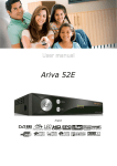
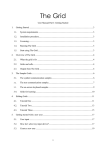
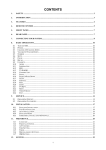
Tops - Series Installation / Operation Manual Digital Video Recorder Tops - Series -- 1 -- Copyright ⓒ 2002 by Woojin Digitech co., Ltd All rights reserved Any content in this operation manual is protected by copyrights. No content in this operation manual may be copied or reproduced without prior approval from copyright. The content in this operation manual may be changed for reasons such as improvement in product, faults in technology, or misprints. • Windows 98, Windows ME, Windows 2000 and Windows XP are Microsoft registered brands. REVISION HISTORY Manual Date Comments TOPS Series Manual 5/12 Program version 2.0 This operation manual was written for the 16 channel model. The This operation manual was written for the 16 channel model. The content in parts of the manual may be different from each other models. content in parts of the manual may be different from each other models. -- 2 -- Tops - Series Table of Contents 1. WARING & CAUTION ‥ ‥ ‥ ‥ ‥ ‥ ‥ ‥ 5 4. CONFIGURATION MODE ‥ ‥ ‥ ‥ ‥ ‥ 26 2. SYSTEM INSTALLATION ‥ ‥ ‥ ‥ ‥ ‥ 9 4.1 CAMERA ‥ ‥ ‥ ‥ ‥ ‥ ‥ ‥ ‥ 28 2.1 Product Content ‥ ‥ ‥ ‥ ‥ ‥ 9 4.2 SENSOR / D/O ‥ ‥ ‥ ‥ ‥ ‥ ‥ 30 2.2 System Front Layout ‥ ‥ ‥ ‥ ‥10 4.3 SCHEDULE ‥ ‥ ‥ ‥ ‥ ‥ ‥ ‥ 31 2.3 System Rear Layout ‥ ‥ ‥ ‥ ‥ 11 4.4 D/O SCHEDULE ‥ ‥ ‥ ‥ ‥ ‥ 33 2.4 System Connection ‥ ‥ ‥ ‥ ‥ 13 4.5 SPEED ‥ ‥ ‥ ‥ ‥ ‥ ‥ ‥ ‥ ‥34 2.5 PAN/TILT Camera Connection ‥ 14 4.6 MOTION / COLOR ‥ ‥ ‥ ‥ ‥ 36 2.6 Mounting ‥ ‥ ‥ ‥ ‥ ‥ ‥ ‥ ‥ 15 4.7 EXTERNAL MONITOR ‥ ‥ ‥ ‥ ‥38 2.7 Sensor & D/O Connection ‥ ‥ ‥ 16 4.8 AUDIO ‥ ‥ ‥ ‥ ‥ ‥ ‥ ‥ ‥ 39 3. SURVEILLANCE MODE ‥ ‥ ‥ ‥ ‥ ‥ 18 4.9 NETWORK / HDD ‥ ‥ ‥ ‥ ‥ ‥ 40 3.1 Surveillance Screen Layout ‥ ‥ 20 4.10 PASSWORD ‥ ‥ ‥ ‥ ‥ ‥ ‥ 41 3.2 Screen Division ‥ ‥ ‥ ‥ ‥ ‥ 21 4.11 SHELL ‥ ‥ ‥ ‥ ‥ ‥ ‥ ‥ ‥42 3.3 Select Audio Channel Buttons ‥ 23 5. PAN/TILT Control MODE ‥ ‥ ‥ ‥ ‥ ‥ 46 3.4 Select Camera Buttons ‥ ‥ ‥ ‥ 24 5.1 PAN/TILT Control ‥ ‥ ‥ ‥ ‥ ‥ 47 3.5 D/O Status Indication & Control ‥ 25 5.2 PRESET ‥ ‥ ‥ ‥ ‥ ‥ ‥ ‥ ‥48 3.6 HDD Storage Date Indicator ‥ ‥ 25 -- 3 -- Tops - Series Table of Contents 6. SEARCH MODE ‥ ‥ ‥ ‥ ‥ ‥ ‥ ‥ ‥ 50 7. BACKUP MODE ‥ ‥ ‥ ‥ ‥ ‥ ‥ ‥ ‥ 60 6.1 Search Screen Layout ‥ ‥ ‥ ‥ 51 8. CLIENT (Remote) ‥ ‥ ‥ ‥ ‥ ‥ ‥ ‥63 6.2 Search by Date and Time ‥ ‥ ‥ 52 8.1 Remote Connection ‥ ‥ ‥ ‥ ‥ 64 6.3 Playback Control Buttons ‥ ‥ ‥ 54 8.2 Finding DVR Server at Remote ‥ 65 6.4 Detail Search ‥ ‥ ‥ ‥ ‥ ‥ ‥ 55 8.3 Remote Surveillance Capability ‥67 6.5 Search Screen Zoom & Move ‥ ‥56 9. BACKUP VIEWER ‥ ‥ ‥ ‥ ‥ ‥ ‥ ‥ 68 6.6 Filtering ‥ ‥ ‥ ‥ ‥ ‥ ‥ ‥ ‥56 10. WATERMARK VIEWER (Option) ‥ ‥ ‥70 6.7 Print Preview and Print ‥ ‥ ‥ ‥ 57 11. PROGRAM INSTALLATION ‥ ‥ ‥ ‥ ‥73 6.8 Disk Save ‥ ‥ ‥ ‥ ‥ ‥ ‥ ‥ 58 12. SYSTEM SPECIFICATION ‥ ‥ ‥ ‥ ‥ 75 6.9 Save AVI File‥ ‥ ‥ ‥ ‥ ‥ ‥ ‥58 6.10 Smart Search ‥ ‥ ‥ ‥ ‥ ‥ 59 -- 4 -- Tops - Series 1. WARNING & CAUTION ! -- 5 -- Tops - Series 1. WARNING & CAUTION INSTALLATION INSTRUCTION 1) This device designed to operate under Max. 40℃. When you install this device in the rack, please consider the Max. ambient temperature. Please install this device proper ambient temperature of all part. 2) CAUTION : When you install this device in the rack, the operating ambient temperature may be greater than room ambient. Please consider this condition and simulate the Max. temperature and install in an environment compatible temperature. 3) Reduced Air Flow : Installation of this device in a rack should be such that the amount of air flow required for safe operation of this device is not compromised. Please provide enough space to get the proper air flow. 4) Mechanical Loading – Mounting of this device in the rack should be such that a hazardous condition is not achieved due to uneven mechanical loading. 5) Circuit Overloading : Please read the rating in the nameplate and consider appropriate power supply and supply wiring. 6) When you are using like a power strips except direct connections to the branch circuit, please make sure to connect reliable earthing maintained. NOTE: This equipment has been tested and found to comply with the limits for a Class A digital device, pursuant to part 15 of the FCC rules. These limits are designed to provide reasonable protection against harmful interference when the equipment is operated in a commercial environment. This equipment generates, uses, and can radiate radio frequency energy and, if not installed and used in accordance with the instruction manual, may cause harmful interference to radio communications. Operation of this equipment in a residential area is likely to cause harmful interference in which case the user will be required to correct the interference at his own expense. Connecting Power source to System Using 110V power source. Make sure power select switch set to 115V(110V use) Using 220V power source Make sure power select switch set to 230V(220V use) NOTICE: For U.S.A and Canada regions; use only UL listed CSA labeled detachable power cord, 3-conductor, 18 AWG, SVT or SJT type, plug rounding type parallel blade, cord connector body-IEC 320 style to mate with appliance inlet on product. IMPORTANT The only way to disconnect power completely is to unplug the power cord. Make sure at least one end of the power cord is within easy reach so that you can unplug the computer when you need to. CAUTION: DANGER OF EXPLOSION IF BATTERY IS INCORRECTLY REPLACED. REPLACE ONLY WITH THE SAME OR EQUIVALENT TYPE RECOMMENDED BY THE MANUFACTURER. DISCARD USED BATTERIES ACCORDING TO THE MANUFACTURER’S INSTRUCTIONS. WARNING This is a class A product. In a domestic environment this product may cause radio interference in which case the user may be required to take adequate measures. Changes or modifications not expressly approved by the manufacturer could void the user’s authority to operate the equipment. -- 6 -- Tops - Series 1. WARNING & CAUTION WARNING & CAUTION 1) Avoid direct sunlight, heating equipment and electric equipment. (Danger of fire) 2) Do not place any liquid filled objects on the product. (May cause fire, electric shock or other injuries) 3) Do not place or drop metallic objects (coins, hair pin, metal) or easily flammable products (matches, paper) in the ventilation of the product. (May cause fire or electric shock) 4) Do not place heavy objects on product. (May cause injury) 5) Make sure to properly insert the power plug. (May cause fire if the connection is unstable) 6) When cleaning the product, do not use water, but use a dry cloth to gently wipe the product. Please do not use chemicals or detergent as they cause the outer coating to damage. 7) When in notice of smoke or weird smell, please stop usage and pull out the power plug and contact the service center. (Continued usage may cause fire or electric shock) 8) Do not pull the power plug with wet hands. (Danger of electric shock) 9) Do not pull on the power cord. 10) Do not install product in areas of high humidity, dust or is soot-covered. (May cause fire or electric shock if cord is damaged) (May cause fire, electric shock or defects.) 11) Do not drop the product or cause sudden impacts. 12) Avoid areas of magnetic fields and severe vibration. (May cause defect in product.) 13) Avoid installation in cold areas. 14) Do not disassemble or reconstruct product. (May cause fire, electric shock or defects) 15) In case of DVR is return to operate after outage, please check the DVR operate normally. 16) We recommend to check and change CPU Cooling fan and Filter once a year. Contact to manufacture and distributor for change. 17) Back up the important data. To prevent loss of data. Any loss of data will not be covered under the warranty. This symbol indicates that dangerous voltage constituting a risk of electric shock is present within this unit. ! This symbol indicates that there are important operating and maintenance instruction in literature accompanying this unit. -- 7 -- CAUTION RISK OF ELECTRIC SHOCK. DO NOT OPEN. Tops - Series 2. SYSTEM INSTALLATION -- 8 -- Tops - Series 2. SYSTEM INSTALLATION 2.1 Product Content 2 1 4 3 6 5 7 Option RS-485 Converter 1 DVR System 2 Manual 3 Keyboard 4 Program CD & Windows CD 5 Rack Mount , Screw & Key 6 Mouse 7 Power Cable 8 485 Converter 8 -- 9 -- Tops - Series 2. SYSTEM INSTALLATION 2.2 System Front Layout POWER 2 HDD 1 4 POWER SW 3 1 Power LED The LED will turn on green when power is on. 2 Hard Disk LED Will blink red whenever video and audio is saved in HDD. 3 Power Switch Switch ON/OFF the DVR. 4 3.5 inch Floppy Disk Drive Used to install and back up on 3.5 inch floppy disks. -- 10 -- Tops - Series 2. SYSTEM INSTALLATION 2.3 System Rear Layout 13 12 14 15 1 1 2 3 10 6 4 9 17 16 7 5 AC Power Input 8 10 Power Voltage Selection Switch 11 12 Mouse/Keyboard Input 13 USB (Universal Serial Bus) Port Terminal used to connect USB devices or Hub. 5 14 COM1 Serial Port COM2 Serial Port PTZ, modem, other device connection. 8 9 16 Sensor Inputs 8 sensors inputs. Speaker & Microphone Connection Exterior speaker & MIC connector. TV Out2 (VIDEO OUT2) Analogue monitor connector (CCTV Monitor). [Division screen] Printer connector. 7 TV Out1 (VIDEO OUT1) Analogue monitor connector (CCTV Monitor). [Rotation screen] 15 LPT1 Printer Port Termination Switch 75Ω termination. PTZ, modem, other device connection. 6 Camera Inputs (VIDEO IN) CCD cameras connector. Mouse and Keyboard connector. 4 Audio (Microphone) Input Port Microphone connector. Voltage select switch 115V and 230V. 3 LAN Connection Terminal Ethernet Adapter Connector. Terminal providing power to DVR. 2 11 17 Digital Out 8 digital outputs. Video Output Port PC Monitor connector. -- 11 -- Tops - Series 2. SYSTEM INSTALLATION Point USB (Universal Serial Bus) port USB connection unit – CD-RW, DVD-RW, MODEM, Network HUB, Extension HDD. Termination Switch It helps to keep video signal, 75Ω standard impedance. “ON” - 75Ω, “OFF” – Over 10kΩ.(High Impedance) Termination Switch Use Make switch to “OFF” mode when one camera line is divided to 2 channel and the quality become low. Factory default is set to “ON” mode, 75Ω -- 12 -- Tops - Series 2. SYSTEM INSTALLATION 2. 4 System Connection Power Connection Connect power cable to power input terminal and electric socket. ! WARNING Verify that the voltage is set correctly for user location. Mouse Connection Connect to the mouse terminal in the system’s rear. PC Monitor Connection (Item not included) Keyboard Connection Connect to the keyboard terminal in the system’s rear. Connect to the VGA output terminal. TV OUT Connection (Item not included) Camera connection (Item not included) Connect to video output terminal. Connect to Camera Input Terminal. LAN Connection (Item not included) LPT/Printer Installation (Item not included) For connection to network, Hub or Router. Connect to printer. -- 13 -- Tops - Series 2. SYSTEM INSTALLATION 2. 5 PAN/TILT Camera Connection Close TX+ TX- PAN/TILT RX + RX - TX + PAN/TILT TX - RX + PAN/TILT RX + RX - TX + -- 14 -- RX - TX + TX - PAN/TILT TX - RX + RX - TX + TX - Tops - Series 2. SYSTEM INSTALLATION 2.6 Mounting The DVR may be placed on a flat surface, such as a shelf, or it can be installed in a 19-inch (48.26 cm) equipment rack. • FLAT SURFACE MOUNTING Before placing the unit on a flat surface, attach the rubber feet (supplied) to the bottom of the DVR. The unit may scratch the surface if the rubber feet are not installed. • EQUIPMENT RACK MOUNTING To install the unit in an equipment rack: 1. Attach the handles to the rack ears using four of the Phillips flat head screws (provided). Refer to Figure. 2. Remove the top screw and bottom screw from the left and right side of the DVR. Remove the side plates. Refer to Figure. 3. Use the screws removed from the sides of the DVR and attach the rack ears to the unit. Refer to Figure. 4. Use four of the supplied 10-32 x .75-inch black screws and finishing washers and mount the assembly to a 19-inch (48.26 cm) rack or console. Installation of the assembly may require two persons. We recommends 1RU spacing between units. IMPORTANT: Slots and openings in the cabinet provide ventilation and prevent it from overheating. Do not block these openings. Never place the DVR near or over a radiator or heat register. Do not place it in a built-in installation, such as a rack, unless proper ventilation is provided or distributor instructions have been followed. -- 15 -- Tops - Series 2. SYSTEM INSTALLATION 2.7 Sensor & D/O Connection • Sensor Connection Sensor 1 2 3 4 6 5 7 8 GND Connect one of the sensor leads to the GND terminal and the other lead to the required input terminal. NOTE “Normal Close & Normal Open” types can be used. The sensor type must be set in the SENSOR CONFIGURATION screen • D/O Connection D/O 1 2 3 4 5 6 7 (+) 8 COM (-) Alarm, siren and exterior devices Exterior Power provider( DC12V ) Use DC Adapter (Power Supply) to provide power to sensor and relays NOTE -- 16 -- Tops - Series 2. SYSTEM INSTALLATION • Filter Change The filter is the inside of left part of the front. It plays a role to strain dust not to enter the products in case of air inhalation. Please change the filter once a month or remove dust for reuse. Filter change procedure: 1. Separate the filter to an arrow as following picture. 2. Insert it to the opposite direction from an arrow if you have a new filter. 3. First, get ride of air attached in the separated filter if you do not have a new filter and insert the filter to the opposite direction from an arrow as the following picture. -- 17 -- Tops - Series 3. SURVEILLANCE MODE -- 18 -- Tops - Series 3. SURVEILLANCE MODE LOG IN Before access is allowed, user must log in by selecting one of six access level User ID and entering the password. Level of access may vary for each User ID. 1) 2) 3) 4) 5) 6) 1) User ID – Select User. Access level may vary for each User ID. 2) Password – Password entered is indicated with “*”. 3) Numbers – Virtual password key panel. 4) Reset – Reset entered password. 5) Cancel – Cancel log in. 6) OK – Confirm log in. Log in is allowed when the password is confirmed. NOTE If log in is denied, only default level access will be allowed. -- 19 -- Tops - Series 3. SURVEILLANCE MODE 3.1 Surveillance Screen Layout 2) 1) 3) 10) 11) 12) 13) 14) 15) 16) 4) 5) 6) 7) 8) 9) 1) Current mode indicator – Identifies the mode displayed on the screen. 2) Camera name indicator – Show camera name of current channel. 3) Storage status indicator – Show video storage modes such as normal, motion, sensor, and audio detection. 4) Screen division button 5) Select audio channel buttons – Monitor selected audio channel. 6) Volume control – Controls audio volume. 7) Select camera buttons 8) Digital output status indication and control buttons – Show and controls D/O status. 9) HDD storage data indicator – Show HDD storage status. 10) Current time and date indicator 11) Search mode button – Enter search mode. 12) Pan/tilt control mode button – Enter pan/tilt control mode. 13) Backup mode button – Enter back-up mode. 14) Configuration mode button – Enter configuration mode. 15) Login – 로그인 사용자에 따라 사용권한이 틀립니다. 16) EXIT – DVR program and shuts down. -- 20 -- Tops - Series 3. SURVEILLANCE MODE 3.2 Screen Division Screen Division Buttons Select single-camera or multiple-camera views. Equal division 1 screen division 4 screen division 9 screen division 16 screen division By clicking on the division screen, the screen will return to the original screen, and by clicking again the screen will return to the screen division. NOTE Video display (480FPS) model does not provide the unequal division function. Unequal division 1+5 screen division : 1 main screen and 5 surveillance sub-screens. 1+7 screen division : 1 main screen and 7 surveillance sub-screens. 1+9 screen division : 1 main screen and 9 surveillance sub-screens. 1+12 screen division : 1 main screen and 12 surveillance sub-screens. 1+16 screen division : 1 main screen and 16 surveillance sub-screens. -- 21 -- Tops - Series 3. SURVEILLANCE MODE NOTE By clicking on the sub-screen, it will convert into the full screen, and by clicking on the full screen, it will turn into sub-screen 1. By clicking on the converted screen, it will return to its original screen. The screen division function may be different from on the DVR model and activated number of cameras. Surveillance by sequence, full screen and pop-up Surveillance by sequence : Sequence through display modes for specified time. Specified time may be changed in configuration mode. Full screen : Displays full screen. Pop-up : Channel with motion detected is displayed on screen 1. If motion is simultaneously detected in different channels, each screen will show for a specified time. NOTE You can control the pop-up time through the configuration Æ speed Æ Layout switch interval slider control. -- 22 -- Tops - Series 3. SURVEILLANCE MODE 3.3 Select Audio Channel Buttons Audio channel selection button Select audio channel. The audio channel can be selected only when it is activated in configuration mode. Indicates the chosen audio channel. Indicates audio monitoring is off. Volume Control Controls volume. Use the mouse to increase and decrease volume. To properly listen to the audio, the input signals must be sufficient. NOTE If the installed microphone’s signal is too weak, use an amplifier to amplify the signal. -- 23 -- Tops - Series 3. SURVEILLANCE MODE 3.4 Select Camera Buttons Select camera buttons Under the surveillance mode the selected camera is shown, full screen. Select channel in detailed search mode. Previous Camera : Show cameras previous to current camera. Next Camera : Show next cameras after the current camera. Camera status indicator Number of displayed camera is highlighted. Indicates that camera is not displayed now on screen although the camera is on. Indicates that camera is disabled. -- 24 -- Tops - Series 3. SURVEILLANCE MODE 3.5 D/O Status Indication & Control D/O status indication Shows the D/O status linked to motion or sensor detection. Indicates that respective D/O channel is activated. Indicates that respective D/O channel is not activated. D/O Control Digital Outputs can be activated manually by selecting corresponding button. A D/O is activated only when a linked camera or sensor detects movement. Motion and sensor activated recordings must be scheduled. NOTE Digital Outputs can only be activated by sensor inputs or motion detection, and must be scheduled and associated to a camera. 3.6 HDD Storage Date Indicator 1) 2) 3) 1) Used capacity indicator – Indicates current used HDD capacity in %. 2) Used capacity Indicating bar – Visual Indicates of currently used HDD capacity. 3) Earliest image data indicator – Show the time and date of the first recorded image. -- 25 -- Tops - Series 4. CONFIGURATION MODE -- 26 -- Tops - Series 4. CONFIGURATION MODE 1) 2) 3) 4) 5) 6) 7) 8) 9) 10) 11) 1) CAMERA – Insert camera name, enable camera and camera type, resolution. 2) SENSOR / D/O – Set the Sensor inputs and Digital outputs. 3) SCHEDULE – Specify recording trigger, start time and end time. (FULL, MOTION, SENSOR or AUDIO). 4) D/O SCHEDULE – Digital outputs schedule. 5) SPEED – Set the FPS (frames per second) for continuous recording, motion detection, sensor detection, audio detection and pre-alarm recording. 6) MOTION / COLOR – Alter motion sensitive area (s), adjust color and camera alignment. 7) EXTERNAL MONITOR – Exterior analogue monitor. 8) AUDIO – Enable Audio and sensitivity. 9) NETWORK / HDD – Network connection method and connection name. 10) PASSWORD – Password levels include Administrator, Search User and Client User. 11) SHELL – Stops recording and starts shell mode. When pushing Exit button, changed setup is saved and returns to surveillance mode. The administrator password must be used to enter configuration mode. NOTE -- 27 -- Tops - Series 4. CONFIGURATION MODE 4.1 CAMERA 5) 6) 7) 1) 2) 3) 4) 1) CAMERA ENABLE/DISABLE – Name enable or disable camera. 2) CAMERA NAME – To name a camera drag the cursor over the text in the camera name box and type in the new name. Up to 19 characters can be entered in the box. 3) PAN/TILT – Sets the pan/tilt controller attached to the camera. 4) RESOLUTION – Select digital image size from 160x120,320x240,640x480. 5) CAMERA TYPE – Set the NTSC/PAL signal to the correct camera setting for your location. 6) RX PORT – Select direct communication port to be connected to pan/tilt controller. (COM1/COM2) 7) EXIT – Saves new setup and returns to surveillance mode. NTSC (National Television System Committee) Used in 44 countries. (Korea, Japan, US, Canada, Taiwan……) NOTE PAL (Phase Alternation Line) Used in 100 countries. (China, Australia, Germany, UK, Brazil……) -- 28 -- Tops - Series 4. CONFIGURATION MODE Types of pan/tilt controllers (RX Controller) that can be setup NOTE RX Type Manufacture Line Info Interface Type Remark PELCO-D Pelco 2400-8-N-1 RS-485 USA Ultrak FastScan Ultrak 9600 -8-N-1 RS-485 USA Protocol-P Pelco 9600 -8-N-1 RS-485 USA DynaColor V2.5 DynaColor 9600 -8-N-1 RS-485 Taiwan PIH-717 LI-LIN 9600 -8-N-1 RS-485 Taiwan Samsung SPD 1600 Samsung Electronics 9600 -8-N-1 RS-485 Korea -- 29 -- Tops - Series 4. CONFIGURATION MODE 4.2 SENSOR / D/O 5) 6) 7) 8) 1) 2) 3) 4) 1) Camera Numbers – Indicates camera numbers. 2) Linked Sensor – Sets the Sensor linked to camera. (Multi-channel capable) 3) Linked Digital Out – Sets the D/O channel to be activated when Sensor linked to camera is detected. 4) RESET – Erases all current setup. 5) SENSOR TYPE – Select from Normally open and Normally closed mode. 6) D/O TYPE – Select from Normally open and Normally closed mode. 7) DEFAULT – Sets camera, Sensor and D/O to same camera channel. 8) EXIT – Saves setup and returns to surveillance mode. The sensor is only activated when the recording starts due to sensor trigger. NOTE D/O is only activated according to the D/O activation schedule. -- 30 -- Tops - Series 4. CONFIGURATION MODE 4.3 SCHEDULE 3) 2) 1) 4) 5) 10) 11) 12) 6) 1) 2) 7) 8) 9) Camera selection – Selects camera to be schedule. HOLIDAY - It set a specific date at holiday and "Sunday" it video tapes with same schedule ◀ / ▶ - Previously month / Next Month Add – Date addition Monthly Add – One month addition Yearly Add – One year addition < / << - The item elimination which is added / Total the items elimination which is added OK – Saved Cancel – Holiday set cancellation -- 31 -- Tops - Series 4. CONFIGURATION MODE 3) ALL CAMERAS – Selects all cameras. 4) ALL DAYS – Selects all days. 5) RESET – Erases all current schedule. 6) AUTO REBOOT – Sets auto restart. ※ Auto restart mode must be selected in order for the following items to appear on screen. 7) Auto reboot days selection – Select auto restart day. (ALL DAYS, Sunday, Monday, Tuesday, Wednesday, Thursday, Friday, Saturday) 8) Auto reboot hour selection – Select auto restart hour. 9) Auto reboot minute selection – Select auto restart minute. 10) Recording method selection – Schedule recording trigger. 9-1) FULL - Sets schedule for continuous recording. 9-2) MOTION - Sets schedule for motion detection recording mode. 9-3) SENSOR – Sets schedule for sensor detection recording mode. 9-4) AUDIO – Sets schedule for audio detection recording mode. 9-5) ERASE – Erase previous recording schedule. 11) Recording schedule – Schedule box. Enter schedule with the mouse. 12) EXIT – Saves set-up and returns to surveillance mode. Continuous recording, motion detection, sensor detection and the audio detection recording schedule can be overlapped. NOTE When the continuous recording and triggered recording method are overlapped, the continuous recording mode will automatically convert to triggered recording mode when a trigger occurs and when the trigger stops, automatically returns to continuous recording mode. When the detection recording is overlapped, it will be recorded as overlapped and the number of frames will correspond to the one with the higher detected method. -- 32 -- Tops - Series 4. CONFIGURATION MODE 4.4 D/O SCHEDULE 1) 2) 3) 4) 5) 6) 7) 1) D/O selection – Select D/O to be schedule. 2) ALL D/O – Selects all D/O’s. 3) ALL DAYS – Selects all days. 4) RESET – Erases all current schedule. 5) Set-up method selection – Selects setup method. 5-1) MOTION : Setup motion schedule. 5-2) SENSOR : Setup sensor schedule. 5-3) ERASE : Erase schedule. 6) D/O schedule – D/O schedule is set using the mouse. 7) EXIT – Saves setup and returns to surveillance mode. -- 33 -- Tops - Series 4. CONFIGURATION MODE 4.5 SPEED 1) 2) 3) 4) 11) 12) 13) 5) 6) 7) 8) 9) 10) 1) RECORD GROUP – GROUP1 / GROUP2 / GROUP3 / GROUP4 2) Group Setting - -- 34 -- Tops - Series 4. CONFIGURATION MODE 3) RECORD MODE - Sets recording speed specific to recording mode. (per second) 3-1) Normal : Configures the capture rate for continuous recording. 3-2) Motion : Configures the capture rate for motion triggered recording. 3-3) Sensor : Configures the capture rate for sensor triggered recording. 3-4) Audio : Configures the capture rate for audio triggered recording. 4) LAYOUT SWITCH INTERVAL – Sets layout switch time in surveillance mode. 5) ALL CAMERA – Press this button to control the recording speed for all channels. 6) All channel recording speed setup – Slider to control recording rate for all channels. 7) Recording speed setup – Sets the recording speed for each channel. 8) ALL CAMERA (Pre-Alarm) – All cameras when Motion/Sensor/Audio is detected, images are recorded for the programmed duration (five seconds maximum per camera) before an event happens. 9) All cameras set bar (Pre-Alarm) – Setup All cameras, for Pre-Alarm function the duration (five seconds maximum per cameras) before an event happens. 10) Camera set bar (Pre-Alarm) – Setup camera, for Pre-Alarm function the duration (five seconds maximum per camera) before an event happens. 11) IMAGE QUALITY - Sets the quality of the recorded image. Image quality affects storage capacity and transmission rate. More bandwidth and storage capacity is required for high quality images. 12) COMPRESSION MODE – Select image compression method. 12-1) NORMAL - Compresses image into normal MJPEG mode. 12-2) ENHANCED - Compresses image into enhanced MJPEG mode. 13) EXIT – Saves setup and returns to surveillance mode. NOTE Duplex mode is automatically started when search mode or configuration mode is entered. When using 16 cameras, the maximum recording speed is 90fps is duplex mode. When search or configuration mode is exited, the unit returns to normal recording mode. When using a PAL type camera, the recording speed is reduced by approx. 17% compared to an NTSC type. For example, an NTSC type can record 15 frames per channel while the PAL type can only record 12 frames per channel. For 3009, Frame rate will be reduced to 40% when Camera image size is set to 640 x 480 mode using Audio channel. -- 35 -- Tops - Series 4. CONFIGURATION MODE 4.6 MOTION / COLOR 1) 2) 3) 4) 5) 6) 7) 8) 15) 16) 9) 10) 11) 12)13)14) 1) Camera selection – Select camera. 2) Brightness – Drag the cursor on the Brightness bar to change the brightness value of the viewed and recorded scene. Adjust the brightness of the scene to compensate for differences in lighting. 3) Contrast – Drag the cursor on the Contrast bar to change the contrast value of the viewed and recorded scene. Proper adjustment will allow maximum gradations between the darkest and lightest parts of a scene. 4) Default – Click the Default Color button to return all color settings to their default settings. 5) Hue – Controls hue. 6) Saturation – Controls saturation. 7) Image location control – Use the image alignment buttons. (up, down, left, right and center) to align the image within the camera frame.) 8) Capture B/D / Display B/D – Toggle between board type. -- 36 -- Tops - Series 4. CONFIGURATION MODE 9) Motion detect area setup method selection 9-1) Full Region : All areas 9-2) User Defined : User can set specific regions. 10) Sensitivity – Adjusts the sensitivity of the detect regions for the selected camera. 11) Apply to All Camera – The current motion setup is applied to all cameras. 12) Move/Size – Used when changing the size of the detection region. 13) Reset – Deletes previously set motion detection regions. 14) Motion detect status – Blinks when there is movement. 15) Motion detect area setup window – Set using the mouse. Motion status can be checked through this window. 16) EXIT – Saves setup and returns to surveillance mode. Motion detection sensitivity is affected by the camera’s performance and what it’s recording. NOTE There can be a big difference, especially between day and night. Therefore, motion detection sensitivity must be adjusted according to the time and environment in order to maximize performance. -- 37 -- Tops - Series 4. CONFIGURATION MODE 4.7 EXTERNAL MONITOR 2) 1) 3) 7) 4) 5) 6) 1) FIXED MODE : Display only the selected channels. 2) ROTATION MODE : Automatically display according to programmed order. 3) Spot Mode 3-1) Sensor : Display the sensor detection image to TV output. 3-2) Motion : Display the motion detection image to TV output 4) Sequence setup – Select the channel sequence for rotation mode. 5) DEFAULT – Return the spot monitor sequence for each camera to defaults. 6) RESET – Resets spot monitor status to default. (Spot monitor disabled) 7) EXIT – Saves setup and returns to surveillance mode. ※ Channel sequence setup 1) Reset conversion order by pressing reset button. 2) Enable channels in the order you wish to view them 3) Only select the channel that you want to display. -- 38 -- Tops - Series 4. CONFIGURATION MODE 4.8 AUDIO 5) 6) 1) 2) 3) 4) 1) AUDIO ENABLE/DISABLE – Activation/deactivation of the audio channel. 2) Audio detection status indicator – Blinks when detecting audio. 3) Camera – Associate the audio channel with a specific camera. 4) Gain Control – Controls the input gain of audio. 5) Audio Sensitivity – Controls sensitivity of audio detection. The status can be checked through the detection indicator. 6) EXIT – Saves setup and returns to surveillance mode. The audio data is automatically recorded when the linked video channel is recording. NOTE Audio puts a lot of overhead on the system. Mute is recorded if the audio channel is activated, even if the microphone is connected, Deactivate all channels not in use. -- 39 -- Tops - Series 4. CONFIGURATION MODE 4.9 NETWORK / HDD 3) 4) 5) 6) 7) 1) 2) 1) HDD – List of all installed HDDs. 2) HDD Information & Configuration - Shows information on selected HDD. 3) LOCAL NAME – Enter DVR network name as supplied by IT administrator. 4) CONNECTION TYPE – Selected a TCP/IP or MODEM. 5) PORT – Firewall open port. 6) SELECT BACKUP HDD – Click the button to exclusively use a drive as a hard disk backup drive. (Clicking button again reverses this action) (DVR cannot record to a HDD once it is setup as a HDD backup drive) 7) EXIT – Saves setup and returns to surveillance mode. DVR server can not allow simultaneous connections by the modem and TCP/IP. NOTE However, it is different when the modem user uses the TCP/IP. When the network setup is changed, the DVR program restarts automatically. -- 40 -- Tops - Series 4. CONFIGURATION MODE 4.10 PASSWORD 3) 4) 5) 6) 7) 1) 2) 1) Select User 1-1) Administrator : Allows access to all DVR functions. 1-2) User1~5 : Log in (Allows access to functions assigned by Administrator) 1-3) Default User : Log off (Allows access to functions assigned by Administrator.) 2) PASSWORD – OLD PASSWORD / NEW PASSWORD / CONFIRM 3) Number/Reset/Enter Buttons – Use number/reset/enter buttons to input password. 4) User Name – Enter user name. 5) Function Access – Enables/disables access to PTZ control /Search /Backup functions. 6) Camera Access – Enables/disables channel accessibility. 7) EXIT – Saves setup and returns to surveillance mode. The password must be a number maximum 12 digits. NOTE Factory default is set to “0”. -- 41 -- Tops - Series 4. CONFIGURATION MODE 4.11 SHELL 1) 2) 3) 4) 5) This mode enable the user to : restore and fix the DVR when windows launches, uninstall the DVR program, check network setting, check the HDD and shutdown. 1) Explorer - Run ‘Windows Explorer’. 2) DVR Doctor - Restore any corrupted data if any problems occur with DVR. 3) DVR - Enter DVR mode / Start recording. 4) Configuration Setting – Setup the system configuration. 5) System shutdown – Shut down the DVR system. Data problem caused by Power failure can not be 100% fixed. Use of UPS equipment is recommended. NOTE It is recommended that In the event of poor quality video verify the quality of the video source. -- 42 -- Tops - Series 4. CONFIGURATION MODE • DVR Doctor 1) 2) 3) 4) 1) Check Start – Check and restore the recorded image data files. 2) System File Initialize – Default the configuration. 3) Delete All Existing Data – Delete all recorded data files. 4) Close – Close the DVR Doctor. Exercise caution when using “System File Initialize” and “Delete All Existing Data”. NOTE -- 43 -- Tops - Series 4. CONFIGURATION MODE • Configuration Setting 7) 1) 8) 9) 2) 3) 10) 4) 11) 12) 5) 13) 6) 1) Shell icons 2) Run Doctor Program if Abnormal Closed – ON/OFF 3) Task Manager - Run task manager. 4) Power Off/Shutdown – Used the not POWER OFF. 5) Control Panel – Network, time and date and printer setting. 6) OK – Save and exit. 7) Text Color (Change Color) – Changed the icon name color 8) Selected Color (Change Color) – Changed the select icon name color 9) Register User App – Registry application program. (Auto created the ICON) 10) Program Version – DVR program version of view. 11) Uninstall DVR. 12) Save Configuration Files/Load Configuration Files – Save or Load the Recording schedule. 13) Cancel – Quit to shell mode. -- 44 -- Tops - Series 5. PAN/TILT CONTROL MODE -- 45 -- Tops - Series 5. PAN/TILT CONTROL MODE 5.1 PAN/TILT Control The screen converts to the pan/tilt screen when pressing the pan/tilt button on the surveillance screen. With the pan/tilt camera installed, based on the camera & control box type, one can use the up, down, left, right, zoom, focus and preset function. 1) 2) 3) 4) 5) 6) 7) 8) 9) 10) 1) Preset – Control the high-speed dome cameras preset function. 2) Camera – Power on/off the camera. 3) Light – Power on/off the lighting. 4) Wiper – Turn on/off the wiper located on the camera exterior. 5) Auto Run – Automatic tour of duty. 6) Mouse Control – PTZ speed and Mouse Control for PTZ 7) Focus – Controls cameras focus. 8) Zoom – Increase/reduce cameras image. 9) Control Key – Moves the camera up, down, left and right. 10) PTZ Protocol Name Ú The number in the center of the control panel shows the camera number being controlled. NOTE The pan/tilt control function can be limited according to the type of RX receiver and camera. When in notice of fault in movement, please check the camera and RX receiver type. -- 46 -- Tops - Series 5. PAN/TILT CONTROL MODE 5.2 PRESET Controls the high-speed dome camera’s preset capability. The Preset capability allows the user to automatically move the camera to a pre determined location. 1) 2) 3) 4) 5) 6) 7) 8) 9) 1) Duration – Sets the dwell time. 2) Preset position numbers – Each preset has a number assigned. 3) Set – Press this button to a preset location. 4) Clear – Deletes preset location. 5) Move – Moves to preset location. 6) Preset Tour – Automatically moves to preset location in sequence. -- 47 -- Tops - Series 5. PAN/TILT CONTROL MODE 7) Zoom – Increase/reduces camera’s image. 8) Control – Moves camera up, down, left and right. up Select camera left right down 9) PAN/TILT Type – Shows the currently selected high-speed dome camera model name. PRESET selection method ① Press the set button. ② Capture to image location using the canted and zoom button. ③ Press the preset button to memorize location. ④ Repeat steps ①-③. To move to PRESET location ① Press the move button. ② Press the preset number to move the camera to desired location. To delete PRESET location ① Press the Clear button. ② Press the preset number button to delete the preset location. -- 48 -- Tops - Series 6. SEARCH MODE -- 49 -- Tops - Series 6. SEARCH MODE 6.1 Search Screen Layout The search button to change from surveillance mode to search mode. 1) 2) 3) 8) 9) 10) 11) 12) 4) 5) 6) 7) 1) Camera name – Shows current channel camera name. 2) Recorded status – Shows mode in which video was recorded. 3) Recorded date – Shows time and date of recorded data. 4) Screen division – Selects screen division mode. 5) Volume control – Control audio volume. 6) Video channel select and convert – Selects video channel. 7) Playback control and time search (Hour and minute) 8) Detail search – Converts to detail search mode.(print and disk backup, zoom …) 9) Year and Month to Search – Displays year and month to search. 10) Day Search - Days with recordings are highlighted with a yellow circle. The day selected is highlighted with a green circle. 11) Daylight search. 12) EXIT – Exits search mode. -- 50 -- Tops - Series 6. SEARCH MODE 6. SEARCH MODE 6.2 Search by Date and Time 1) 2) 3) 4) 1) Year/Month – Selected year and month for search. 2) Day - Selected day for search. When the desired date, indicated with the green circle, is selected, the video map screen for the selected date will appear. 3) Fast recorded day 4) Daylight Search - ON – Daylight search on. OFF - Daylight search off. -- 51 -- Tops - Series 6. SEARCH MODE Video map Recording modes/times are displayed visually and can be selected with the mouse. 1) 2) 7) 3) 4) 5) 6) 1) Time – 0 ~ 24hours. The time scale will enlarged by clicking on the blue bar. 2) Displays date 3) Open – Open video at selected time. 4) Video search bar – Using can search for desired time using the mouse. 5) Cancel – Ends search process and closes video map window. 6) Time display slider bar – Changes period of time displayed on video map. 7) Video recorded status indicator – Shows mode in which video was recorded. DVR skips some frames when you playback in multi screen division search mode. Go to one channel detail to view all image. NOTE It playbacks audio with video when video is recorded with audio data. -- 52 -- Tops - Series 6. SEARCH MODE 6.3 Playback Control Buttons 1) 2) 3) 4) 9) 10) 11) 12) 13) 5) 6) 7) 8) 1) Search time selection slider 2) Enter search by hour 3) Enter search by minute 4) Enter search channel 5) Video recorded mode indicator – Shows selected channel’s recorded mode. 6) Playback 7) Fast playback 8) Backward 9) Go to the first image 10) Previous image – Selected the previous image in sequence. 11) Next image – Selected the next image in sequence. 12) Go to last image 13) Stop – Stops playing recorded images. -- 53 -- Tops - Series 6. SEARCH MODE 6.4 Detail Search Enter detailed search mode. 1) 2) 3) 5) 7) 9) 4) 6) 8) 10) 11) 13) 12) 1) Brightness – Controls brightness of viewed image. 2) Contrast – Controls contrast of viewed image. 3) Pan – Use mouse to move viewed image. 4) Zoom - Use mouse to enlarge viewed image. 5) Save image – Save selected image to disk. 6) Filtering – Sharpens image quality. 7) print - Print image. 8) Print preview - Print preview mode and print setup. 9) AVI Backup - Back up using standard AVI file.(Only FDD) 10) Show/Hide Thumbnail image. 11) Smart Search 12) Image preview. 13) EXIT – Ends detail search and returns to search mode. -- 54 -- Tops - Series 6. SEARCH MODE 6.5 Search Screen Zoom & Move Select the zoom button. Left click image, hold the mouse button and drag the mouse right to enlarge image. Left click image, hold the mouse button and drag the mouse left to reduce image. [Enlarge] [Reduce] Select the move button. Left click and hold the mouse button The screen will move according to the direction the screen is being dragged. [Left, right] [Up, down] 6.6 Filtering Image filter -- 55 -- Tops - Series 6. SEARCH MODE 6.7 Print Preview and Print The user can preview the image before it is printed by clicking on the ‘preview image’ button. 1) 2) 3) 4) 5) 6) 7) 8) 9) 10) 1) Print – Prints preview image. 2) Print setup – Configure printer. 3) Previous – When the previewed pages exceed one page, the previous page is displayed. 4) Next – When the previewed pages exceed one page, the next page is displayed. 5) Zoom In – Enlarges preview image. 6) Zoom Out – Reduces preview image. 7) 1 x 2 – Preview in 1 x 2 layout. 8) 2 x 4 – Preview in 2 x 4 layout. 9) 4 x 8 – Preview in 4 x 8 layout. 10) Close – Closes print preview window. When printing directly using the print button, images will be printed only in NOTE 1x2 layout. -- 56 -- Tops - Series 6. SEARCH MODE 6.8 Disk Save After selecting the image(s) from the thumbnail view the image(s) can be saved by clicking the save button. The images can be saved in either Bitmap or JPEG format. The file names are automatically saved as follows. NOTE CAM_0_Camera #1_2001-8-8_7-30-33.53 Camera No. Camera name Date Time If the file name is not entered, the files will be saved as default. If the file name is entered, the files will be saved as [entered file]01, [entered file]02 … bmp/jpg 6.9 Save AVI File Saves the FDD in AVI format. AVI file backup to FDD only. NOTE 1 frame per second. -- 57 -- Tops - Series 6. SEARCH MODE 6.10 SMART SEARCH 2) 4) 5) 6) 3) 7) 8) 9) 10) 11) 12) 1) 1) User Defined Areas 2) Sensitivity – Adjust sensitivity 3) Full – Entire area 4) Add – Add defined area (click and drag pointer on the area) 5) Move – Move defined area (drag to new area with pointer) 6) Reset – Clear defined area(s) 7) Key Image Set – Search in defined area(s) only 8) Next Play – Continue Play 9) Back Play – Reverse 10) Stop – Stop Play 11) OK - The SMART the search window it closes and it moves at the hour when it is searched 12) Cancel – Cancel Smart Search This feature allows users to search for activities in key area(s). ADD(define area) Æ Key Image Set Æ Next Play -- 58 -- Tops - Series 7. BACKUP MODE -- 59 -- Tops - Series 7. BACKUP MODE 7.1 DVR Data File Backup The back-up window will appear upon pressing the back-up button. 2) 3) 4) 5) 6) 7) 8) 9) 10) 11) 12) 13) 1) 1) Calendar 2) Recorded (BLUE) 3) Selected data for backup (Gray) 4) Selected data size 5) Reset 6) Free space / Total Space 7) Target – Selected target drive (Backup drive) 8) Format 9) Eject 10) Backup progress state 11) Close - Ends back-up and closes back-up window. 12) Hide - Hides back-up window. Back-up continues 13) Start / Stop -- 60 -- Tops - Series 7. BACKUP MODE A peripheral backup device must be installed to use this feature. * Recommended backup devices • • • • • CD-RW DVD-RW USB-Memory HDD USB-HDD Network Drive 9 Media Format Place the disk Æ Select target drive Æ Start Format 9 Backup Choose date from Calendar Æ Select time length by dragging the mouse) Æ select target drive Æ Start backup 9 Stop Stop backup while in process Æ Click on Stop 9 Hide backup window Hide while in process Æ Click on Hide -- 61 -- Tops - Series 8. CLIENT -- 62 -- Tops - Series 8. CLIENT (Remote) 8.1 Remote Connection Install the Client program and the remote DVR program will start. 1) 2) 3) 4) 5) 6) 7) 8) 1) NETWORK CONNECTION – Displayed the NETWORK CONNECTION Window 2) CONNECTION TYPE – Select the connection type. 3) CONNECTED DVR LIST 4) RETRY COUNT OF AUTO CONNECTION – Shows connection progress with DVR. 5) Find – Finds for connected DVR units. 6) Connection – Connect to selected DVR. 7) Cancel – Cancels connection and closes connection window. 8) Beep – Event (Motion & Sensor) the warning beep -- 63 -- Tops - Series 8. CLIENT (Remote) 8.2 Finding DVR server at remote 1) 2) 3) 4) 5) 6) 7) 8) 9) 1) Registry – Selected the server or connection site. (ALL – All connected DVR server will be displayed here.) 2) New – Click “New” enter detail in 5) & 6) and click OK. 3) Update – Click the “Update” button to Save. 4) Delete – Click the “Delete” button to clear the server or site. 5) SERVER NAME – Enter the server name or site name. 6) IP ADDRESS / PHONE NUMBER – Enter the IP address or phone numbers. 7) PORT NUMBER – Enter the Network port number. 8) OK – Click the OK button to connect. 9) Cancel. -- 64 -- Tops - Series 8. CLIENT (Remote) User password verification 1) 2) 3) 4) 5) 1) SELECT LEVEL - Use the left mouse button to select a password level.. (Administrator, Search user, Client User) 2) Password – Input area text box. 3) Number Buttons – Use number buttons to input password. 4) OK – Select to apply password to level. 5) Cancel – Connection Cancel. -- 65 -- Tops - Series 8. CLIENT (Remote) 8.3 Remote Surveillance Capability Remote DVR access The method in operating the DVR client is identical to that of the DVR server. The client has access to all capabilities including surveillance, search, pan/tilt and set-up. Limits in remote DVR access 1) The remote program compresses the image data, therefore the image may not be as clear, and can not provide real-time video due to bandwidth limitations. 2) With a modem, the user can view one frame every 3 seconds, therefore in order to minimize the delay, the user should convert to 1x1 layout. 3) With remote pan/tilt, because of the lag in time, the user would be better off using a faster connection. 4) The user can not remotely access the DVR server backup capability. 5) The user can not remotely reset any of the DVR server programs. (Changing of camera type, focus, activate/non-activate, and network name) The DVR server’s performance is affected when a client is connected. NOTE When not in use, please end the connection. -- 66 -- Tops - Series 9. BACKUP VIEWER -- 67 -- Tops - Series 9. BACKUP VIEWER Install the Backup Viewer program. The following screen will appear when the program is launched. Media search Daylight Search Press the media search button. Select the folder where the DVR files are saved. Select the files to be viewed Select backup folder The operation of searching and playing backup data is identical to the method used for the DVR server. The user has access to detailed search capability in Backup Viewer. -- 68 -- Tops - Series 10. WATERMARK VIEWER -- 69 -- Tops - Series 10. WATERMARK VIEWER (Option) Watermarking – Technology used in inserting specified data such as copyright information that is undetectable through the human eye or ear, in multimedia contents such as audio, video and images. Hence, watermarks are hidden data inserted in order to verify the originality of the contents. The watermark can be an image or text. Upon purchase, loading the included CD will allow for the following screen to appear. Clicking the watermark viewer on the installation screen will properly install the program. 1 2 3 4 1 Folder – Select folder with Water Viewer type files. 2 Address - Indicates currently selected folder. 3 List - Will show list of Water Viewer type files. 4 Shows image 1 Select Folder - Select folder with Water Viewer type files. 1 2 2 Display Modified Area - Select to show or hide transformed image. 3 3 Exit Shows Water Viewer version. -- 70 -- Tops - Series 10. WATERMARK VIEWER (Option) Original image Transformed image Current image related message ! Message - The image has not been altered. The image has been altered or has not been watermarked. If the file type is not compatible with the Watermark Viewer, the files can not be viewed By this program. NOTE -- 71 -- Tops - Series 11. PROGRAM INSTALL -- 72 -- Tops - Series 11. PROGRAM INSTALL 1 2 4 5 6 3 7 8 9 NOTE 1 DirectX 8.1 Install 2 Select camera type 3 Install appropriate DVR server program 4 Install Client 5 Install Backup Viewer 6 Install Watermark Viewer 7 Install VGA, LAN, Sound Card driver 8 Run Windows explorer 9 Exit The DVR server program is affected by the specifications of the hardware, therefore install only the model number as indicated on the chassis. -- 73 -- Tops - Series 12. SYSTEM SPECIFICATION -- 74 -- Tops - Series 12. SYSTEM SPECIFICATION Maximum image Display Maximum recording speed TOPS-7016 TOPS-6016 TOPS-5016 TOPS-4016 480 frame/sec 480 frame/sec 480 frame/sec 480 frame/sec 120 frame/sec 30 frame/sec 270 frame/sec (320x240) 240 frame/sec (320x240) Focus 160X120, 320X240, 640X480 160X120, 320X240, 640X480 160X120, 320X240, 640X480 160X120, 320X240, 640X480 Compressed Image SIZE 2 ~ 15 Kbytes / frame 2 ~ 15 Kbytes / frame 2 ~ 15 Kbytes / frame 2 ~ 15 Kbytes / frame Image compression Method MJPEG Enhanced MJPEG MJPEG Enhanced MJPEG MJPEG Enhanced MJPEG MJPEG Enhanced MJPEG Screen split mode “1, 4, 9, 16”, “1+5, 1+7,1+9, 1+12, 1+16” “1, 4, 9, 16”, “1+5, 1+7,1+9, 1+12, 1+16” “1, 4, 9, 16”, “1+5, 1+7,1+9, 1+12, 1+16” “1, 4, 9, 16”, “1+5, 1+7,1+9, 1+12, 1+16” Remote connection LAN, MODEM LAN, MODEM LAN, MODEM LAN, MODEM Detection method Motion, Sensor, Audio Detection Motion, Sensor, Audio Detection Motion, Sensor, Audio Detection Motion, Sensor, Audio Detection Camera input 16 CH 16 CH 16 CH 16 CH Sensor/control 8 CH 8 CH 8 CH 8 CH PAN/TILT capability Possible Possible Possible Possible Audio 8 CH 8 CH 4 CH 1 CH TOPS-3016 TOPS-3009 TOPS-2004 TOPS-2016 TOPS-1016 Maximum image Display 240 frame/sec 270 frame/sec 120 frame/sec 30 frame/sec Maximum recording speed 240 frame/sec 270 frame/sec 120 frame/sec 30 frame/sec Focus 160X120, 320X240, 640X480 160X120, 320X240, 640X480 160X120, 320X240, 640X480 160X120, 320X240, 640X480 Compressed image SIZE 2 ~ 15 Kbytes / frame 2 ~ 15 Kbytes / frame 2 ~ 15 Kbytes / frame 2 ~ 15 Kbytes / frame Image compression method MJPEG Enhanced MJPEG MJPEG Enhanced MJPEG MJPEG Enhanced MJPEG MJPEG Enhanced MJPEG Screen split mode “1, 4, 9, 16”, “1+5, 1+7,1+9, 1+12, 1+16” “1, 4, 9”, “1+5, 1+7,1+9” “1, 4”, “1+5” “1, 4, 9, 16”, “1+5, 1+7,1+9, 1+12, 1+16” Remote connection LAN, MODEM LAN, MODEM LAN, MODEM LAN, MODEM Detection method Motion, Sensor, Audio Detection Motion, Sensor, Audio Detection Motion, Sensor, Audio Detection Motion, Sensor, Audio Detection Camera input 16 CH 9 CH 4 CH 16 CH 16 CH Sensor/control 8 CH 8 CH 4 CH 8 CH 8 CH PAN/TILT capability Possible Possible Possible Possible Audio 8 CH 8 CH 4 CH 1 CH -- 75 -- Tops - Series