1
THE PROFESSIONAL AND EURO VENT HOOD
Installation
Guide
MODELS:
VS30
VS1236
VS36
ES30
VS48
ES36
0®®
A MESSAGE TO OUR CUSTOMERS
Thank you for selecting
developed
this DCB Professional
this lnstalfation
Guide. It contains
for years of safe and enjoyable
Vent Hood. Because of this appliance's
valuable
information
on how to properly
unique
features
we have
install your new appliance
cooking. Keep this guide handy, as it wift help answer questions
that may arise as
you use your new appliance.
For your convenience,
1-888-281-5698,
product
questions
can be answered
emaih support(_dcsappliances.com,
by a DCB Customer
Care Representative
by phone:
or by mail:
Fisher & Paykel Appliances, Inc.
Attention: DCS Customer Care
5900 Sky,JabRoad
Huntington Beach, CA 92647
www.dcsappliances.com
APPROVED FOR INDOOR
COOKING APPLIANCES AND RESIDENTIAL USE ONLY.
PLEASE READ ENTIRE iNSTRUCTIONS
Installation
must comply
BEFORE PROCEEDING.
with ali IocM codes.
WARNING
If the information
in this manual is not followed exactly, a fire or explosion
may result causing property damage, personal injury or death. Do not store or
use gasoline or other flammable vapors and liquids in the vicinity of this or any
other appliance.
WARNING
To reduce the risk of injury to persons in the event of a rangetop
observe the following:
grease fire,
Turn burner off first. Smother flames with a close-fitting
lid, cookie sheet, or metal tray. Be careful to prevent burns. If the flames do not
go out immediately
evacuate
and carl the fire department.
Never pick up a
flaming pan - You may be burned.
DO NOT USE WATER, including
wet
dishcloths or towels - a violent steam explosion will result. Use an extinguisher
ONLY if:
1) You know you have a Class ABC extinguisher,
how to operate it.
2) The fire is small and contained
3) The fire department
and you akeady
know
in the area where it started.
is being called.
4) You can fight the fire with your back to an exit.
Z_
SAFETY WARNING:
Turn off power circuit at service panel and lock out panel, before wiring
appliance.
Requirement: 120 V AC, 60 Hz. 15A (minimum) Branch Circuit
PLEASE RETAIN THIS MANUAL
FOR FUTURE REFERENCE.
this
A MESSAGE TO OUR CUSTOMERS
FOR YOUR SAFETY
If You Smell Gas:
t Do not try to light any appliance.
t Do not touch any electrical switch; do not use any phone in your building.
l Immediately
callyour gas supplier from a neighbor's
phone. Follow the
gas supplier's instructions.
I If you cannot reach your gas supplie_ call the fire department.
[] Installation
and service must be performed
by a qualified installer, service
agency or the gas supplier
TABLE OF CONTENTS
SAFETY PRACTICES......................................................................................................................................................
3-5
PRODUCT
DIMENSIONS
...............................................................................................................................................
d
PARTS ........................................................................................................................................................................................
7
BEFORE INSTALLING
HOOD .................................................................................................................................
8-9
INSTALLATION ............................................................................................................................................................
10q5
Wall[ Mount
HnstaHHation................................................................................................................................
10q2
Cabinet hsta[[ation
Integral Ventilator
HOW TO OBTAIN
WARRANTY
........................................................................................................................................
] 3q 4
Installation
..........................................................................................................................
15
SERVICE ........................................................................................................................................
1d
..........................................................................................................................................................................
17
SAFETY PRACTICES AND PRECAUTIONS
CAUTION:
For general
ventilating
explosive materials
Z_
use only.
DO NOT use to exhaust
hazardous
or
to persons, observe
the
or vapors.
WARNING:
To reduce the risk of fire, electrical
following
shock, or injury
:
A. Use this unit only in the manner intended
the manufacturer.
by the manufacturer,
if you have questions, contact
B. Before servicing or cHeaning the unit, switch power offat service paneH and Hockservice paneH
disconnecting
means to prevent power from being switched on acddentaHy. When the service
disconnecting
means cannot be Hocked,secureHy fasten a prominent warning device, such as a
tag, to the service panel
C. hstaHation work and eHectricaHwiring must be done by quaHified person(s) in accordance
all applicable codes & standards, including fire-rated construction.
with
D. Sufficient air is needed to maintain proper combustion
and safe exhausting of gases through
the flue (chimney) of fuel burning equipment
to prevent backdrafting.
Follow the heating
equipment
manufacturers
guideline and safety standards such as those published by the
National Fire Protection Association (NFPA),the American Society for Heating, Refrigeration and
Air Conditioning
Engineers (ASHRAE), and the local code authorities.
E. When cutting
utilities.
or drilling
into wall or ceiling, do not damage electrical
wiring
and other hidden
F. Ducted systems must always be vented to the outdoors.
CAUTION:
To reduce the risk of fire and to properly
outside. Do not vent exhaust
exhaust ai# be sure to duct air to
air into spaces within
walls or ceiling, nor into
attics, crawl spaces, or garages.
/_
WARNING:
To reduce the risk of fire, use only metal duct work.
Install this hood in accordance
Z_
with a[[ requirements
specified.
WARNING:
To reduce the risk of fire or electric shock, do not use this hood
external
solid state speed control device.
with any
SAFETY PRACTICES&
Z_
WARNING:
To reduce the risk of a range top grease
fire:
A. Never Heave surface units unattended
at high settings. BoHovers cause smoking
spHHovers that may ignite. Heat oiHshowily on How or medium settings.
B. AHways turn hood"ON'when
Cherries JubiHee, Peppercorn
C. CHeanventilating
cooking at high heat or when flambeing
Beef FHambe').
fans frequently.
food (i.e.Crepes Suzette,
Grease shouHd not be aHHowedto accumuHate on fan or fiHter.
D. Use proper pan size. AHways use cookware
Z_
and greasy
appropriate
for the size of the surface unit.
WARNING:
To reduce the risk of injury to persons, in the event of a range top grease fire,
observe the following:
A. SMOTHER FLAMES with a cHose-fitting Hid,cookie sheet, or other metal tray, then turn offthe
gas
burner or the electric element. BE CAREFUL TO PREVENT BURNS. If the flames do not go out
immediately, EVACUATE AND CALLTHE FIRE DEPARTMENT.
B. NEVER PICK UP A FLAMING PAN - you may be burned.
C. DO NOT USE WATER, including wet dishcloths or towels - a violent steam explosion
DO NOT use water on a grease fire. Burning grease and water will explode.
D. Use an extinguisher
may result.
ONLY if:
1)
You know you have a class ABC extinguisher,
and you already know how to operate
2)
The fire is small and contained
3)
The fire department
4)
You can fight the fire with your back to an exit.
it.
in the area where it started.
is being called.
NOTE: Unit MUST be vented to the outside of the building.
IMPORTANT: Refer to ducting
z_
information
suppfied
in this Manual
( Pg. 9)
WARNING:
To reduce
be installed
the risk of electrical
with ventilators
shock
or injury to persons,
that have been approved
all vent hoods
must
for use with the hood.
SAFETY PRACTICES & PRECAUTIONS
This Vent Hood system is designed to remove smoke, cooking
Z_
vapors and odors from the cooktop
area.
WARNING:
All wall and floor openings
where the vent hood is installed
must be sealed.
Consuff the cooktop or range installation instructions given by the manufacturer before making any
cutouts.
MOBHLE HOME INSTALLATION- The installation
of this Hood must conform
to the
Manufactured
Home Construction
and Safety Standards, TitHe 24 CFR, Part 3280 (formerly
Standard for Mobile Home Construction
must be used and the app[hnce
wiring
[] DO NOT use 4" hundry-type
[] F[exiMe-type
ductwork
[] DO NOT obstruct
available.
requirements
on page 1.
wall caps.
the flow of combustion
requirements
and ventilation
air. Be sure a fresh air supply
is
may result in a fire.
is required on this Hood.
[] ffco[d water pipe is interrupted
for grounding.
[] DO NOTground
must be revised. See electrical
is not recommended.
[] Failure to follow venting
[] Electrical ground
Federal
and Safety, TitHe 24, HUD, Part 280). Three wire power supply
by plastic, non-metallic
gaskets or other materials, DO NOT use
toa gas pipe.
[] DO NOT have a fuse in the neutral or grounding
circuit could result in electrical shock.
[] Check with a qualified
electrician
circuit.
A fuse in the neutral or grounding
if you are in doubt as to whether
the Hood is properly
grounded.
[] Failure to follow electrical
requirements
may result in a fire.
[] Be sure a[[ the range and/or cooktop controls are turned off and the appliance is coo[ before
using any type of aerosol cleaner on or around the appliance.The chemical that produces the
spraying action could, in the presence of heat, ignite or cause metal parts to corrode.
[] Clean the ventilator hood and filters above the range or cooktop
cooking vapors does not accumulate on them.
[] Service should only be done by authorized
supply before servicing this appliance.
,/_
technicians.Technicians
frequently
so grease from
must disconnect
the power
WARNING:
California
Proposition
by-products
reproductive
potential
65 - The burning
of gas cooking
fuel generates
some
which are known by the State of California to cause cancer or
harm. California law requires businesses to warn customers of
exposure
to such
substances.
To minimize
exposure
to these
substances, always operate this unit according to the instructions contained in
this booklet and provide good ventilation
to the room when cooking with gas.
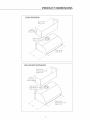
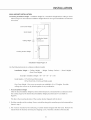
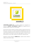
PRODUCT DIMENSIONS
EURO VENTHOOD
ES3O= 29-718"
/
ES36= 35-718"
/
8"or 12" _"
{Duc:t Cover
A(c:essory
Height)
<.
ES30= 29-7/8"
ES38= 35-7/8"
WALL MOUNT VENTHHOOD
VS30= 29-718"
VS38/VS'_236=
j_
35-7/8"
V548= 47-7/8"
J
6,,or12,,_
_"
{Duct Cover
Accessory
Height)
VS30= _4-_5116"
VS361VS_238=
17-15111
VS48= 23-15118"
VS3O= 29-7/8"
/
VS36/VS_238=
VS48= 47-7/8"
35-7/8"
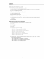
PARTS mNCLUDEDWmTHYOUR HOOD
n Hood Canopy Assembly with Light Bulbs installed.
m MetaH Transition
with Back draft dampers (aHready instaHHedon ES30, ES36,VS30,VS36 modeHs)
m Use & Care/HnstaHHation Hnstructions
m FHters (quantity
depending
on modeH and size)
n Screws and DrywaHHAnchors
n Wooden
Strip for Hood Support
m Drip Trays (quantity
depending
on modeH and size)
m FHterTdm Bracket (ES36 modeH onHy - HnstaHH
on unit after eHectricaHconnections
on page 15)
are compHeted
m HntegraHBHower
PARTS NOT INCLUDED
m Ducting
WITH YOUR HOOD
(See Page 9 for duct requirements:8"or
10"0 to be used.)
m Duct Tape
m 1/2" Conduit
m Wire Nuts
m Optiona[ duct cover,6"or
12" height
VDC1230
- 12" Duct cover kit for VS30/ES30
VDC1236
- 12" Duct cover kit for VS36/VS1236/ES36
VDC1248
- 12" Duct cover kit for VS48
VDC630 - 6" Duct cover
kit for VS30/ES30
VDC636 - 6" Duct cover
kit for VS36/VS1236/ES36
VDC648 - 6" Duct cover
kit for VS48
Optional HRKit + support bracket
175W maximum infrared buHbs).
(Hnfrared bulbs included.
HB30- Kit with singHe 175 W heat [amp for VS30/ES30
HR36- Kit with two 175 W heat [amp for VS36/VS1236/ES3d
HR48- Kit with two 175 W heat [amp for VS48
Use only
bulbs rood. 175R-PAR,
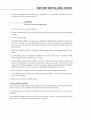
BEFORE INSTALLING HOOD
1. For the most efficient
air flow exhaust, use a straight
run or as few elbows
as possible. Maximum
duct [ength is 40 feet, incHuding eHbows.
CAUTION:
Vent unit to outside of building
on!yo
2. Two peopHe are necessary for instaHHafion.
3. The hood is fitted with Screws and Drywall Anchors suitable
installer.
for most surfaces.Consult
a qualified
4. Do not use flex ducfing.
5. COLDWEATHER installations
should have an additional
back flow of coHd air and nonmetaHHk therma[
atures as part of the ductwork.
thermal break.
The damper
backdraff
damper installed to minimize
break to minimize
should
conduction
of outside
be on the coHd air side (outside
the
temper-
wahl) of the
The break should be as choseas possible to where the ducting enters the heated portion of the
house,
6. Local building
professional
codes may require the installation
for specific requirements
7. Hood installation
improve
approved
height
the efficiency
above cooktop
of capturing
for installation
height is inconvenient.
heights
air system.
is the users preference.
cooking
Consult your HVAC
an installation
8. ES30 and ES36 hood models are not recommended
9. For installation over DCS Range and Cooktop
vent is recommended.
Lower installation
odors, grease, and smoke.
30" above the cooktop.
DCS recommends
10. Make sure your range or cooktop
of a make-up
in your area.
heights
This hood
wi[[
has been
Taller people may find a 30" installation
height between
30"and
36'.'
to be used over indoor range grills.
models
RGS-364GL or CS-364GL, the VS1236 mode[
is [eveN.
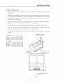
TYPICAL INSTALLATION
The hood can be installed
kitchen.
Ducting
If an infrared
installation.
using a wall mounting
can be configured
kit was purchased
system or suspended
for both vertical and horizontal
for installation
under existing cabinetry
in the
discharge.
with the hood, assemble the kit to the hood prior to
For waN[ mount inst[[ations, duct cover kits can be purchased
Duct covers are assembled to unit after the hood is installed.
as spacers between
hood and ceiling.
BEFORE INSTALLING HOOD
ELELCTRICAL
Hnsta[[a 1/2"conduit
from the service pane[ long enough
Branch circuit requirement
to reach the hood once it is installed.
is 120V, 60Hz, 15A(minimum).
INFRARED LAMP AND PANEL KiT
Optiona[
infrared
Models available:
[amp and pane[ kit can be ordered
separateHy and mounted
[R30, 1R36 and 1R48. See instructions
//_
supplied
into your vent hood.
with kit for assembly
to your hood.
WARNING
To avoid any electrical shock the installation
a qualified
electrician
and before starting
of the IR lamp should be done by
the instafladon
of the hood.
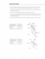
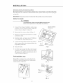
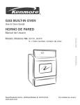
DUCTING
Hood models: ES30, ES36,VS30,VS36 are supplied
of the hood for connection
transition
with damper
Horizontal
and is assembled
Discharge
with a starting collar and backdraft
to 8" round duct. Models:VS1236
damper on top
with a 10" round
as shown in Fig. 3.
F/G. 1
Figure
canopy
and VS48 are supplied
FOR 900 ELBOW
A
10"
8"
16"
11"
is installed
plus 1-1/2 inch to
..__..-_
FIG, 2
install ducting long enough
connect ductwork.
to reach the transition
once the hood
ASSEMBLE TRANSITION
TO HOOD
and VS48 hoods
The transition
supplied
(VS1236
only)
with the hood mounts to the top of the
hood, Figure 3.
1. Place the transition piece over the hood exhaust
secure with 4 screws provided (Figure 3).
2. Duct tape connection
between
3. Remove tape holding
damper
transition
and
and hood.
FIG. 3
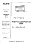
INSTALLATION
WALL MOUNT INSTALLATION
Calculating
Installation
Height - hsta[[ation
bellow in Figure X. The minimum
30"and 36'.'
height
for a standard 8 ft high kitchen ceiling
is shown
instaHHation height aHHowed is 30'.' Typica[ instaHHations are between
Duct Cover Height
12" or
Hood Height
Installation Height
Ceiling Height
8ft
(96")
Cooking Surface Height
30" to 36"
recommended
36"
installation Height Figure X
Use the following
formula
Installation
to calculate installation
Height
= (Ceiling
Height)
height:
-
(Height
Cooktop
Surface)
-
(Hood
Height)
-
(Duct Cover Height)
(Example:
installation
height = 9d"-
36"- 18"- 12"= 30")
Hood Height = 12"for ES30 and ES36 models
18" for VS30,VS36, VS1236 and VS48 models
Duct Cover Height - Duct cover accessories are available
ceilings duct covers can be joined
1. Hood Installation
in d" or 12" heights.
For taller
in any combination.
Height
After the hood installation
the cooktop
together
height has been determined,
equal to the desired hood installation
draw a horizontal
height plus dimension
line at a distance above
"E" (see Table on
Figure 4).
This line is the mounting
2. Find the centerline
location
of the wooden
of the cooktop.
bracket shipped with the hood.
Draw a vertical line along this centerline
up to the horizontal
line
drawn in step 1.
3. The
hood is mounted
to the wail using a wooden
bracket from the hood by removing
two shipping
bracket shipped
with the hood.
screws. Mark the centeriine
10
Remove the
of the bracket.
4. Findstudsbehindthedrywallbytappingthewallor usingastudfinder.Locate
onestudoneither
sideofthecooktopcentedine
touseformounting
thewoodenbracket
asshownin Figure
4.
5. Alignthetopofthewoodbracket
alongthehorizontal
linedrawnin step1.Alignthecenteriines
ofthebracket
andcooktop.
6. DrH[
a 3"deep1/8"hoHe
throughthewoodenbracket,
drywallandintothestud.
7. Use2 to4,1/4"x3"flatheadwoodscrews
toattachthebrackettothewallasshownin Figure
4.
Forsupportof[ongerhoods,
usethreeorfourstudsasavaHaMe.
Countersink
theheadsto prevent
interference
withthehood.
8. Onthewoodbracket,
markthelocations
usedto hangthehoodaccording
toFigure
5anditsTable.
DRYWALL
\\\
HOOD MODEL
DIM."E"
VS Series
15-1/2"
ES Series
10-3/8"
HEIGHT ABOVE
COOKTOP
COOKTOP
CENTERLINE
X_
STUDS
SCREWS
(2 ea. 1/4" x 3")
)ESIRED COOKTOP
HEIGHT + "E"
FIG_4
TO COOKTOP
SURFACE
DRYWALL
HOOD MODEL
DIM."F"
VS Series
7-5/8"
ESSeries
7-9/16"
SCREWS
(2 ea. #10 - 3/4")
FIG. 5
11
COOt<TOP
CENTERLINE
INSTALLATION
9.
DrHNa 1/8" hone through
the studs.
the wooden
bracket and drywaiL
These screws do not need to go into
10. Screw two #10 X 3/4" pan head wood screws into the wood
exposed for hanging
11. Hang the
hood
bracket, leaving
1/4" of the screw
the hood.
using
slots I in
Figure 6. Make sure the wood
bracket fits into the recess on the
back of the hood.
12. Level the hood and tighten
in slot I.
screws
13. From inside the hood, drive 4 or 6
#10 x 3/4" pan head wood
screws
K
(depending
on model) through
holes J into wooden bracket.
14. Fix duct to transition
and seal with
duct
with
screws
tape.
Screws
FIG. 6
must not hamper the damper.
15. Dnil a 3/8" hole through
holes. Tighten
the center of the holes K into the wail. insert two wail plugs into dniied
hood to wall anchors by installing
Go to page 14 to continue
2 screws with washers.
the instal/ation.
ASSEMBLY AND INSTALLATION
OF THE DUCT COVERS:
Opfionai
duct covers shown in Figure 7
may be used to fiNNthe space between
the
hood
and
installations.
are
ceiiing
in wall
6"and 12"high
available
and
may
mount
duct covers
be
ordered
separately.
if multiple
connect
duct
covers
are used,
the pieces together
sheet metal
screws
provided
_
using
with
chimneys.
2.
Attach the duct cover(s) to the hood
using sheet metal screws as shown
in Figure 7.
FiG. 7
12
Attaching
screws
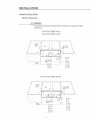
CABINET INSTALLATION
Cabinet Preparation
Z_
WARNING:
The cabinet must be structurMlyjoined
to the wall studs to support
of this hood.
ES30/ES36 SERIES HOOD
VS30/VS36
SERIES HOOD
Bottom of
Cabinetor
Soffit
1 I/2" Dia,Holes
Verticalconduit
option
Cabinet
'_
O
©
/
I
©
A
A) Min.12"
C/L
2"Dia.Holes _
zontalconduit
option
vertical
Discharge
C) 6"
B)
10"
D) 6-3/4"
E) I-7/8"
CutoutWidth
E530=30"
F)
G)
H)
I)
ES36=36"
VS1236/VS48
Bottom of
Cahinetor
Soffit \
SERIES HOOD
Cabinet
O
©
I
©
A
/L
/_11-1/2"
Dia.Holes
J
Horizontal
conduit
Vertical _
Discharge/_
option
CutoutWidth
V530=30"
%36=36"
V548=48"
%!236=36"
13
5-3/4"
5-718"
1-7/8"
S-l/8"
1 1/2" Dia,Holes
Verticalconduit
option
/
©
the weight
INSTALLATION
CABINET INSTALLATION
1.
Find the centeriine
the cabinet,
of the cabinet
bottom,
Draw a line along this centeriine
from rear to front of
Refer to the top of the hood and Fig.8. Draw two lines, one at distance 'K'from
one at distance 'Z'from
centeriine.
determine
3.
Mark 4 points, two along
the screw locations.
cabinet
bottom
Hang the hood on screws through
Dnll a 3/8" hole through
holes. Tighten
5.
each line at a distance
Fit four #10 pan head wood screws on cabinet
space of about 1/2"from
4.
Attach
duct
the wail, the other
the previous line. NOTE:These Hinesmust be perpendicular
Do not tighten
side slots provided
on hood top.Tighten
the center of the holes K into the wall.
with
completely
but leave a
surface and screw heads.
hood to wall anchors by installing
to transition
bottom.
to the cabinet
of half W from the center line, to
the four screws.
Insert two wall plugs into dnlled
2 screws with washers,
screws and sea[ with
duct tape. Screws must not hamper
the
damper.
Side slot for cabinet
bottom mounting
ES SERIES
ES30
K
2-11/16"
6-Z8
''7/
W
29-1/16"
ES36
2-11/16"
6-7/8
35-1/16"
Z
W
VS SERIES
K
Z
K
W
VS30
2-5/8"
7-1/16"
29-1/16"
VS36/VS1236
VS48
2-5/8"
2-5/8"
7-1/16"
7-1/16"
35-1/16"
47-1/16"
Transition with
gackdraft (Top outlet)
Knockouts
(}unction box)
iZ
/
/
Screw for cabinet
installation
FIG. 8
14
bottom
iNSTALLATiON
INTEGRAL VENTILATOR INSTALLATION
The Nntegra[ ventilator can be mounted to discharge air as shown in Figure 9. From the inside of the
hood, ship motor into the bracket on the Heft.Rotate motor upwards unti[ it snaps into the spring chip
on the right.
IMPORTANT:
Secure the motor
to the hood with the machine
screw and [ock washer.
WIRING THE HOOD:
Z_
WARNING:
Turn off electricity et the service panel before wiring the unit.
Branch circuit requirement is 120V, 60Hz, 15A (minimum).
Connect
the
connector
NntegraN Ventilator
to the connector
moNex
present
inside
Integral ventilator
fixing point
pNug
the
hood as shown in Figure 9 or Figure 10.
2.
Remove the j-box cover as shown in Figure 11.
3.
Remove 1 of 2 knockouts
connector
and install 1/2"conduit
/
in j-box.
//
Run Mack, white, and green wires (#18 AWG) in
1/2" conduit from power suppNyto j-box.
\/
Connect the bNack to bNack (hot Nine)wire, white to
Bracket
white
(common
to ground
Nine) wire and green/yeNNow wire
in j-box cover.
C Nose j- box cover.
7.
For ES36 onNy: mount
the
rifler
trim
bracket
on the right side of the hood.Check
all engage points
Motor
connector
Motor
support
/
Spring clip
FIG. 9
6.
supplied
/
/
perfectly
From Control
Pane_
that
match, then fix with 3
screws as shown in figure 12.
Final installation
steps
Replace filters and grease trays as described in the
Use & Care manual.Turn power on at service panel.
Check operation
Motor
of the hood.
FIG. 10
Power
supply
conduit
LOCATIONS
From
_
h
control
pane[ /
tSCREW
FIG, 12
FIG. 11
15
connector
HOW TO OBTAIN SERVICE
BEFORE YOU CALL FOR SERVICE
I Is the circuit
breaker tripped
or the fuse blown?
I Is there a power outage in the area?
For warranty
service,
at (888) 281-5698.
please
Before
contact
your
you ca[[, please
local service
provider
have the following
or DCS Customer
information
Care Representative
ready:
[] Mode[ Number
[] Serial Number
[] Date of installation
[] A brief description
of the probHem
[] Proof of purchase
Your satisfaction
is of the utmost importance
please ca[[,write
or emaH us at:
to us, ffa problem
Write:
Fisher & Payke[ Appliances, [nc,
Attention: DCS Customer Care
5900 Sky[ab Road
Huntington
Beach, CA 92647
emaH: support@dcsa
pp[ia nces,com
16
cannot be resolved to your satisfaction,
LENGTH OF WARRANTY
One (1) Year Fuji parts and Labor Covers the entire product
Five (5) Year Limited
warranty
covering
the switches and motor part only.
DCS WILL PAY FOR
AHHrepair Habor and parts found to be defective
HOME" warranty
other than
due to materhHs or workmanship
during the first year of ownership.
This does not appHy if the unit was subjected
normaH househoHd use. Service must be provided
normaH working
for one fuHHyear'HN
by Authorized
to
Factory Agent during
hours. No charges wHHbe made for repair or repHacement at the Hocation of initiaH
instaHHation or factory for parts returned
pre-paid, through
the deaHer and chimed
within
the warranty
period, and found by DCS to be defective.
Replacement
wH[ be EO.ELDCS, and DCS wH[ not be liable for any transportation
export duties.
This warranty
shah not apply, nor can we assume responsibility
result from failure to follow
tampered
with
negligence,
warranty.
or altered
or accident.
instructions
or which,
Hmp[ied warranty
This warranty
liability in connection
manufactures
in anyway
that might
or local codes, where the appliance
in our judgement,
shah not extend
is in lieu of a[[ warranties
costs, labor costs, or
for damage
expressed
has been
beyond
subjected
the duration
or implied
has been
to misuse,
of this written
and a[[ other obligations
or
with the sale of this appliance.
DCS WILL NOT PAY FOR
m Hnsta[[ation or start-up.
m Shipping damage.
m Service by an unauthorized
agency.
m Damage or repairs due to service by an unauthorized
m Service during other than norma[ working
m Hmproper instaHHation, such as improper
agency or the use of unauthorized
parts.
hours.
hook-up, etc.
m Service visits to teach you how to use the appHiance; correct
breakers, repHace home fuses, cHeaning or maintenance.
the instaHHation; reset circuit
m Repairs due to other than norma[ househoHd use.
m Damage caused from accident, abuse, aHteration, misuse, incorrect
in accordance with [oca[ codes.
instaHHation or instaHHation not
m Units instaHHed in non-residentia[
appHication such as day care centers,
centers, churches, nursing homes, restaurants, hoteHs, schooHs, etc.
This warranty
commercial
applies to appliances
situations.
U.S.A.,the District of Columbia
warranty
used in residential
This warranty
is for products
and Canada.This
period. Should the appliance
the new owner continues
applications;
purchased
warranty
it does not cover their
and retained
use in
in the 50 states of the
applies even if ),,ou should move during the
be sold b),,the original
to be protected
bed and breakfast
until the expiration
purchaser
during
date of the original
the warranty
period,
purchaser's warrant),,
period.
This warranty
including
is in fieu of aft other
warranties
the full extent permitted
duration
particular
of any implied
by law.
warranties,
purpose, are limited
spedfic legal rights.
warranties,
of merchantabifity
expressed
or implied,
and fitness for a particular
To the extent
including
to the duration
that implied
implied
and all implied
warranties
warranties
of this expressed
may not be disclaimed,
of merchantability
warranty.
to
the
and fitness for a
This warranty
You may also have other rights which vary from state to state.
17
warranties,
purpose, are hereby disclaimed
gives you
18
19
20
21
5900 Skylab Road, Huntington Beach, CA 92647
Tel: 714,372,7000 , Fax:714.372.7001
Customer Care: 888,281.5698
www,dcsappliances.com
As product
reserve the
notice.
improvement
is an ongoing
right to change specifications
DCS am#liore constamment
de modifier les sp#cifications
sans aUQUn preavis.
P/N 17797 Rev. B
Litho in USA 11/2004
process at DCS, we
or design without
ses produits et se r#serve le droit
ou la conception
de ses produJts