1
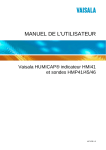
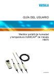
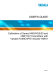
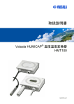
USER'S GUIDE
Calibration of Digital Transmitters with
Vaisala HUMICAP® Humidity Indicator
HMI41
Cables 19164ZZ and 25917ZZ
M210777EN-B
PUBLISHED BY
Vaisala Oyj
P.O. Box 26
FIN-00421 Helsinki
Finland
Phone (int.): +358 9 8949 1
Fax:
+358 9 8949 2227
Visit our Internet pages at http://www.vaisala.com/
© Vaisala 2007
No part of this manual may be reproduced in any form or by any means, electronic or
mechanical (including photocopying), nor may its contents be communicated to a third
party without prior written permission of the copyright holder.
The contents are subject to change without prior notice.
Please observe that this manual does not create any legally binding obligations for
Vaisala towards the customer or end user. All legally binding commitments and
agreements are included exclusively in the applicable supply contract or Conditions of
Sale.
________________________________________________________________________________
Table of Contents
CHAPTER 1
GENERAL INFORMATION............................................................................ 3
Safety......................................................................................... 3
Recycling .................................................................................. 4
Trademarks ............................................................................... 4
Warranty.................................................................................... 5
CHAPTER 2
PRODUCT OVERVIEW.................................................................................. 7
Introduction .............................................................................. 7
HMI41 with Calibration Option .............................................. 7
Selecting HMI41 Calibrator Function .................................... 8
CHAPTER 3
CALIBRATION ............................................................................................. 11
Getting Started ....................................................................... 11
One-Point Offset and Gain Calibrations.............................. 15
HMI41 as a Reference Meter .............................................. 15
HMI41 as a Terminal........................................................... 17
Two-Point Calibration ............................................................ 18
HMI41 as a Reference Meter .............................................. 19
HMI41 as a Terminal........................................................... 21
CHAPTER 4
TROUBLESHOOTING ................................................................................. 25
APPENDIX A
QUICK REFERENCE TO CALIBRATION ................................................... 27
Selecting the Calibrator Function......................................... 27
Offset and Gain Calibrations with HMI41 as a Reference
Meter ........................................................................................ 28
Offset and Gain Calibrations with HMI41 as a Terminal..... 29
Two-Point Calibration with HMI41 as a Reference Meter ... 30
Two-Point Calibration with HMI41 as a Terminal ................ 31
VAISALA_____________________________________________________________________ 1
User's Guide ______________________________________________________________________
This page intentionally left blank.
2 ________________________________________________________________ M210777EN-B
Chapter 1 ________________________________________________________ General Information
CHAPTER 1
GENERAL INFORMATION
This chapter provides general notes for the manual and the product.
Safety
Throughout the manual, important safety considerations are
highlighted as follows:
WARNING
Warning alerts you to a serious hazard. If you do not read and follow
instructions very carefully at this point, there is a risk of injury or
even death.
CAUTION
Caution warns you of a potential hazard. If you do not read and
follow instructions carefully at this point, the product could be
damaged or important data could be lost.
NOTE
Note highlights important information on using the product.
VAISALA_____________________________________________________________________ 3
User's Guide ______________________________________________________________________
Recycling
Recycle all applicable material.
Dispose of batteries and the unit according to statutory regulations.
Do not dispose of with regular household refuse.
Trademarks
HUMICAP® is a registered trademark of Vaisala.
4 ________________________________________________________________ M210777EN-B
Chapter 1 ________________________________________________________ General Information
Warranty
Vaisala hereby represents and warrants all Products
manufactured by Vaisala and sold hereunder to be
free from defects in workmanship or material
during a period of twelve (12) months from the date
of delivery save for products for which a special
warranty is given. If any Product proves however to
be defective in workmanship or material within the
period herein provided Vaisala undertakes to the
exclusion of any other remedy to repair or at its
own option replace the defective Product or part
thereof free of charge and otherwise on the same
conditions as for the original Product or part
without extension to original warranty time.
Defective parts replaced in accordance with this
clause shall be placed at the disposal of Vaisala.
Vaisala also warrants the quality of all repair and
service works performed by its employees to
products sold by it. In case the repair or service
works should appear inadequate or faulty and
should this cause malfunction or nonfunction of the
product to which the service was performed Vaisala
shall at its free option either repair or have repaired
or replace the product in question. The working
hours used by employees of Vaisala for such repair
or replacement shall be free of charge to the client.
This service warranty shall be valid for a period of
six (6) months from the date the service measures
were completed.
This warranty is however subject to following
conditions:
a) A substantiated written claim as to any alleged
defects shall have been received by Vaisala
within thirty (30) days after the defect or fault
became known or occurred, and
b) The allegedly defective Product or part shall,
should Vaisala so require, be sent to the works
of Vaisala or to such other place as Vaisala may
indicate in writing, freight and insurance
prepaid and properly packed and labelled,
unless Vaisala agrees to inspect and repair the
Product or replace it on site.
This warranty does not however apply when the
defect has been caused through
a) normal wear and tear or accident;
b) misuse or other unsuitable or unauthorized use
of the Product or negligence or error in storing,
maintaining or in handling the Product or any
equipment thereof;
c) wrong installation or assembly or failure to
service the Product or otherwise follow
Vaisala's service instructions including any
repairs or installation or assembly or service
made by unauthorized personnel not approved
by Vaisala or replacements with parts not
manufactured or supplied by Vaisala;
d) modifications or changes of the Product as well
as any adding to it without Vaisala's prior
authorization;
e) other factors depending on the Customer or a
third party.
Notwithstanding the aforesaid Vaisala's liability
under this clause shall not apply to any defects
arising out of materials, designs or instructions
provided by the Customer.
This warranty is expressly in lieu of and excludes
all other conditions, warranties and liabilities,
express or implied, whether under law, statute or
otherwise, including without limitation any implied
warranties of merchantability or fitness for a
particular purpose and all other obligations and
liabilities of Vaisala or its representatives with
respect to any defect or deficiency applicable to or
resulting directly or indirectly from the Products
supplied hereunder, which obligations and
liabilities are hereby expressly cancelled and
waived. Vaisala's liability shall under no
circumstances exceed the invoice price of any
Product for which a warranty claim is made, nor
shall Vaisala in any circumstances be liable for lost
profits or other consequential loss whether direct or
indirect or for special damages.
VAISALA_____________________________________________________________________ 5
User's Guide ______________________________________________________________________
This page intentionally left blank.
6 ___________________________________________________________________ M210777EN-B
Chapter 2 __________________________________________________________ Product Overview
CHAPTER 2
PRODUCT OVERVIEW
This chapter introduces the features, advantages, and the product
nomenclature.
Introduction
HMI41 with Calibration Option
Vaisala HUMICAP® Humidity Indicator HMI41 can be used as a field
calibrator for various Vaisala humidity transmitters. There are four
different calibration cables available:
- 19116ZZ for the calibration of HMD/W60/70 and HMP140 series
analogue transmitters
- 19164ZZ for the calibration of HMP230 series digital
transmitters
- 19165ZZ for the calibration of the HMD/W20/30 and HMP130
series analogue transmitters
- 25917ZZ for the calibration of HMT100/HMT330 series digital
transmitters
Note that HMI41 has to meet the same requirements as the transmitter
to be calibrated. There are three calibration modes available: offset
(dry point), gain (wet point) and two-point calibration. All of these
can be performed using HMI41 either as a reference meter (for
example when the transmitter is mounted in an air-conditioning
channel) or only as a terminal for visualizing and setting the
transmitter's RH reading (for example when the transmitter does not
have a local keypad and it is calibrated against salt solutions without a
personal computer).
VAISALA ________________________________________________________________________ 7
User's Guide ______________________________________________________________________
Calibration is quick and easy to perform. In calibration, HMI41
measures relative humidity with the reference probe and receives the
RH information from the transmitter. HMI41 sends the measured or
manually set reading to the transmitter which makes calculations and
necessary corrections. The data is then stored in the transmitter
memory.
Selecting HMI41 Calibrator
Function
The desired calibrator function is selected in the HMI41 setup menu.
To enter the setup mode, first press the ON/OFF button and the
following appears:
RH
%
Td
°C °F
T
°C °F
P
set min max
g/m hPa
hyst hold Lo bat Hi
Then release the ON/OFF button and within 1 ... 2 seconds press both
ENTER and MODE buttons until the following text appears on the
display:
After a few seconds, the text changes automatically to show the
following:
°C
set
If the basic settings of HMI41 (display units, automatic power off
function, display quantities and pressure) have to be changed, please
refer to the HMI41 User's Guide. Otherwise, press ENTER repeatedly
until the following text appears:
8 ___________________________________________________________________ M210777EN-B
Chapter 2 __________________________________________________________ Product Overview
set
The number on the first line of the display corresponds to the
following HMI41 functions:
1
2
=
=
3
=
4
=
HMI41 as a humidity and temperature indicator
HMI41 as a calibrator for HMD/W60/70 and HMP140 series
analogue transmitters
HMI41 as a calibrator for HMP230 and HMT100/HMT330
series digital transmitters
HMI41 as a calibrator for the HMD/W20/30 and HMP130
series analogue transmitters
To calibrate HMP230, HMT100 or HMT330 series digital
transmitters, select number 3 with buttons ▲ (number up) and ▼
(number down) and then press ENTER. The following text appears:
set
If the baud rate on the HMI41 display is not the same as that of the
transmitter, change it with buttons ▲ and ▼. Use baud rate 19200 (=
19.2 on the HMI41 display) with the HMT100 and HMT330 series.
When the baud rate is the same, press ENTER and the following
appears:
set
Letters and numbers correspond to the following:
E
7
1
=
=
=
even parity
data bits
stop bits
VAISALA ________________________________________________________________________ 9
User's Guide ______________________________________________________________________
These are also the factory settings of the HMP230 series. If the values
on the HMI41 display do not correspond to those of the HMP230
series transmitter, change them with buttons ▲ and ▼ until they are
correct, press ENTER and then ON/OFF. With the HMT100 and
HMT330, use N, 8, 1:
N
8
1
=
=
=
none parity
data bits
stop bits
These selections are stored in the HMI41 memory; when HMI41 is
turned on again, it will automatically wake up as a calibrator for
digital transmitters with these line settings. If you wish to calibrate
transmitters with different settings, or use HMI41 as an indicator or as
a calibrator for some other transmitter type, these selections have to be
made accordingly; refer to corresponding manuals for further details.
10 __________________________________________________________________ M210777EN-B
Chapter 3 _______________________________________________________________ Calibration
CHAPTER 3
CALIBRATION
There are four ways for calibrating the HMP230, HMT100 and
HMT330 series transmitters with HMI41. You can perform a onepoint offset or gain calibration using the HMI41 probe as a reference,
or you can use HMI41 only as a terminal. Alternatively, you can
perform a two-point calibration using the HMI41 probe as a reference,
or you can use HMI41 only as a terminal. Offset and gain calibrations
are performed in the same way and differ only for internal
calculations. Two-point calibration is more accurate, and includes
both offset and gain corrections. For performing a two-point
calibration, you need two separate measurement points with a
difference of at least 50 %RH between them.
NOTE
Two-point calibration is not supported for HMT100.
When the transmitter does not have a local keypad and it is calibrated
against salt solutions without a personal computer, HMI41 can be
used as a terminal for visualizing and setting the transmitter's RH
reading.
For a successful calibration, it is essential that the probe of HMI41
and that of the transmitter are at the same temperature, and that the
reference probe has been previously calibrated. Always allow enough
time for the readings to stabilize. Note that the stabilization time
depends on the ambient conditions and may vary from 10 minutes to a
couple of hours.
Getting Started
After having selected the desired function (Selecting HMI41
Calibrator Function on page 8) and checked the line settings, turn
VAISALA _______________________________________________________________________ 11
User's Guide ______________________________________________________________________
HMI41 off and connect the calibration cable to the EXT connector at
the bottom of HMI41 (Figure 1 below). Connect the other end of the
cable to the connector X5 in the HMP230 transmitter (Figure 2 on
page 13). The connector X5 is also used for mounting the RS485/422
serial port module or current loop module; if a module is mounted, it
must first be removed (for further details, see the HMP230 series
User's Guide).
When calibrating series HMT100 transmitters, connect the cable to
Service port RJ45 connector (RS232C) on the connector board, inside
the housing.
When calibrating series HMT330 transmitters, connect the cable to
Service Port RJ45 connector (RS232C) on the cover, inside the
housing.
0605-009
Figure 1
Location of HMI41 Calibration Connector
12 __________________________________________________________________ M210777EN-B
Chapter 3 _______________________________________________________________ Calibration
0605-010
Figure 2
Calibration Connector X5 in Series HMP230
Transmitters
0605-011
Figure 3
Service Port in Series HMT100 Transmitters
VAISALA _______________________________________________________________________ 13
User's Guide ______________________________________________________________________
0605-012
Figure 4
Service Port in Series HMT330 Transmitters
After having connected the cable, turn HMI41 on with the ON/OFF
button and wait until the following text appears on the display:
RH
If you press the HOLD button, you will go on to two-point calibration
mode, and if you press the MODE button, you will go on to gain
calibration mode. You can return to offset calibration mode from twopoint or gain calibration modes by pressing MODE or HOLD
repeatedly. As offset and gain calibrations are performed in the same
way, the following chapter is valid for both. For two-point calibration,
see Two-Point Calibration on page 18.
14 __________________________________________________________________ M210777EN-B
Chapter 3 _______________________________________________________________ Calibration
One-Point Offset and Gain
Calibrations
Select the desired calibration with buttons ▲ and ▼. Select offset
calibration if the humidity is < 65%RH and gain calibration if the
humidity is > 65%RH:
RH
RH
or
Press ENTER to acknowledge the selection. A text similar to the
following appears on the display:
RH
%
In following chapters, you will find instructions for performing offset
and gain calibrations in two different ways.
HMI41 as a Reference Meter
The HMI41 reference probe is used to show the correct humidity
value. Connect the cable and wait for the transmitter and reference
probe readings to stabilize; when both readings are stable, press
ENTER to conclude the calibration. When ENTER is pressed, the
transmitter reading is corrected to the HMI41 reference probe reading.
RH
%
Numbers on the first line indicate the RH measured by the transmitter,
and numbers on the second line indicate the RH measured by the
reference probe. Let the readings stabilize.
VAISALA _______________________________________________________________________ 15
User's Guide ______________________________________________________________________
If you prefer, you can change the display to show the difference in
readings. Press HOLD and a text similar to the following appears:
RH
%
Numbers on the first line indicate how much the transmitter reading
differs from that of the HMI41 reference probe. Numbers on the
second line indicate the RH measured by the reference probe. You can
return to the previous display by pressing HOLD again.
When the readings have stabilized, press ENTER in either of these
two display modes to conclude the calibration. If the calibration has
been successful, the following text appears:
RH
The data is now stored in the transmitter memory. If the calibration
has not been successful, the following appears:
RH
In this case, perform the calibration again. Whether the calibration
was successful or not, HMI41 always returns to show the selected
calibration mode:
RH
RH
or
After having successfully completed the calibration, turn HMI41 off
and disconnect the cable.
16 __________________________________________________________________ M210777EN-B
Chapter 3 _______________________________________________________________ Calibration
HMI41 as a Terminal
If the transmitter does not have a local keypad and it is calibrated
against salt solutions, HMI41 can be used for visualizing and setting
the transmitter's RH reading manually.
RH
%
Numbers on the first line indicate the RH measured by the transmitter,
and numbers on the second line indicate the RH measured by the
HMI41 probe. Let the readings stabilize and press MODE. The
following appears:
RH
%
set
HMI41 now works only as a terminal for setting the humidity reading.
Numbers on the first line are blinking, and numbers on the second line
indicate the RH measured by the transmitter.You can now set the
blinking reading to the correct value (for example to the equilibrium
RH of the salt solution) with buttons ▲ and ▼. Press ENTER to
conclude the calibration. If the calibration has been successful, the
following text appears:
RH
The data is now stored in the transmitter memory. If the calibration
has not been successful, the following appears:
RH
VAISALA _______________________________________________________________________ 17
User's Guide ______________________________________________________________________
In this case, perform the calibration again. Whether the calibration
was successful or not, HMI41 always returns to show the selected
calibration mode:
RH
RH
or
After having successfully completed the calibration, turn HMI41 off
and disconnect the cable.
Two-Point Calibration
In two-point calibration mode, both offset and gain corrections are
made. This calibration mode is more accurate than offset or gain
calibrations. For performing a two-point calibration you need two
reference points with a difference of at least 50 %RH between them.
NOTE
Two-point calibration is not supported for HMT100.
Select two-point calibration with buttons ▲ and ▼:
RH
Press ENTER and the following text appears on the display for about
1 ... 2 seconds:
RH
18 __________________________________________________________________ M210777EN-B
Chapter 3 _______________________________________________________________ Calibration
HMI41 as a Reference Meter
RH
Normally, the HMI41 reference is needed for calibration. Insert the
HMI41 probe and the transmitter probe to the lower humidity. Within
1 ... 2 seconds the display changes automatically to show a text similar
to the following:
RH
%
Numbers on the first line indicate the RH measured by the transmitter,
and numbers on the second line indicate the RH measured by the
reference probe. Let the readings stabilize. If you prefer, you can
change the display to show the difference in the readings. Press
HOLD and a text similar to the following appears:
RH
%
Numbers on the first line indicate how much the transmitter reading
differs from that of HMI41. Numbers on the second line indicate the
RH measured by the reference probe. You can return to the previous
display by pressing HOLD again. Let the readings stabilize. Press
ENTER, and the following appears:
RH
VAISALA _______________________________________________________________________ 19
User's Guide ______________________________________________________________________
Insert both probes to the higher humidity. Within 1 ... 2 seconds, the
display changes automatically to show a text similar to the following:
RH
%
Numbers on the first line indicate the RH measured by the transmitter,
and numbers on the second line indicate the RH measured by the
reference probe. Let the readings stabilize. If you prefer, you can
change the display to show the difference in the readings. Press
HOLD and a text similar to the following appears:
RH
%
Numbers on the first line indicate how much the transmitter reading
differs from that of the HMI41 reference probe. Numbers on the
second line indicate the RH measured by the reference probe. You can
return to the previous display by pressing HOLD again.
When the readings have stabilized, press ENTER in either of these
two display modes to conclude the calibration. If the calibration has
been successful, the following text appears:
RH
The data is now stored in the transmitter memory. If the calibration
has not been successful, the following appears:
RH
20 __________________________________________________________________ M210777EN-B
Chapter 3 _______________________________________________________________ Calibration
In this case, perform the calibration again. Whether the calibration
was successful or not, HMI41 always returns to show the selected
calibration mode:
RH
After having successfully completed the calibration, turn HMI41 off
and disconnect the cable.
HMI41 as a Terminal
HMI41 can also be used only as a terminal for visualizing and setting
the transmitter's RH reading (for example when the transmitter does
not have a local keypad and it is calibrated against salt solutions
without a personal computer).
RH
Insert the transmitter probe to the lower humidity. Within 1 ... 2
seconds the display will automatically change to show a text similar to
the following:
RH
%
Numbers on the first line indicate the RH measured by the transmitter,
and numbers on the second line indicate the RH measured by the
HMI41 probe.
VAISALA _______________________________________________________________________ 21
User's Guide ______________________________________________________________________
Let the readings stabilize. Press MODE and a text similar to the
following appears:
RH
%
set
Numbers on the first line are blinking, and numbers on the second line
indicate the RH measured by the transmitter. You can now set the
blinking reading to the correct value (for example to the equilibrium
RH of the salt solution) with buttons ▲ and ▼. Press ENTER, and
the following appears:
RH
Insert the transmitter probe to the higher humidity. Within 1 ... 2
seconds, the display will automatically change to show a text similar
to the following:
RH
%
Numbers on the first line indicate the RH measured by the transmitter,
and numbers on the second line indicate the RH measured by the
HMI41 probe. Let the readings stabilize. Press MODE, and a text
similar to the following appears:
RH
%
set
22 __________________________________________________________________ M210777EN-B
Chapter 3 _______________________________________________________________ Calibration
Numbers on the first line are blinking, and numbers on the second line
indicate the RH measured by the transmitter. You can now set the
blinking reading to the correct value (for example to the equilibrium
RH of the salt solution) with buttons ▲ and ▼. Press ENTER to
conclude the calibration. If the calibration has been successful, the
following text appears:
RH
The data is now stored in the transmitter memory. If the calibration
has not been successful, the following appears:
RH
In this case, perform the calibration again. Whether the calibration
was successful or not, HMI41 always returns to show the selected
calibration mode:
RH
After having successfully completed the calibration, turn HMI41 off
and disconnect the cable.
VAISALA _______________________________________________________________________ 23
User's Guide ______________________________________________________________________
This page intentionally left blank.
24 __________________________________________________________________ M210777EN-B
Chapter 4 ___________________________________________________________ Troubleshooting
CHAPTER 4
TROUBLESHOOTING
In the following table you will find a summary of the few error
messages that may appear during calibration:
Table 1
Display:
RH
Troubleshooting Table
What to Do:
What is the Reason?
This message may
appear for example if
Perform the calibration the difference between
the reference
again.
humidities in two-point
calibration is too small.
Wait.
This message may
appear during
calibration when
HMI41 is trying to
contact the transmitter.
Check the connection
of the calibration cable.
Check that the line
settings in the HMI41
memory correspond to
those of the
transmitter.
The calibration cable is
not correctly
connected.
The line settings of
HMI41 and the
transmitter do not
correspond.
VAISALA _______________________________________________________________________ 25
User's Guide ______________________________________________________________________
This page intentionally left blank.
26 __________________________________________________________________ M210777EN-B
Appendix A _______________________________________________Quick Reference to Calibration
APPENDIX A
QUICK REFERENCE TO CALIBRATION
It is recommended that this quick reference guide is used only as a
checking list for those who already know how to operate HMI41 as a
calibrator. For those who take it into use for the first time, the User's
Guide gives useful information that is not included in this quick
reference guide.
Selecting the Calibrator Function
For selecting the calibrator function, press ON/OFF until you can see
some text on the display. Then release the ON/OFF button and press
within 1 ... 2 seconds both ENTER and MODE buttons until the text
"setup" appears on the display. Then follow the instructions of the
table below.
Display:
What to Do
Press
Wait for a few seconds.
°C
set
set
If the basic settings have been
given, press ENTER.
Press ENTER repeatedly:
If they have not been given,
refer to the HMI41 User's Guide.
Select the HMI41 function:
1 = indicator
2 = calibrator for HMD/W60/70
and HMP140 series analogue
▲ (number up) or
transmitters
▼ (number down)
3 = calibrator for HMP230 or
ENTER
HMT100/330 transmitters
4 = calibrator for HMD/W20/30
and HMP130 series transmitters
VAISALA _______________________________________________________________________ 27
User's Guide ______________________________________________________________________
Display:
What to Do
Check that the baud rate
corresponds to that of the
HMP230 transmitter (4.8 - 4800
baud), or HMT100/330
transmitters (19.2 - 19200
baud).
Check that these line settings
correspond to those of the
HMP230 transmitter (E, 7, 1), or
the HMT100/330 transmitters
(N, 8, 1).
set
set
Press
▲ (number up) or
▼ (number down)
ENTER
▲ (number up) or
▼ (number down)
ENTER
ON/OFF
Offset and Gain Calibrations with HMI41 as a
Reference Meter
Display:
What to Do
RH
%
Td
°C°F
T
°C°F
Pabs
set min max
Press
HMI41 has been turned on.
g/m Pa
hyst hold Lo bat Hi
Indication of the software
version (if the version is 1.02 or
more)
Indication of the battery voltage.
bat Hi
RH
RH
%
RH
%
Select the desired calibration
mode:
offset : humidity < 65%RH
gain : humidity > 65%RH
▲ (number up) or
▼ (number down)
ENTER
Let the readings stabilize.
Conclude the calibration.
Alternatively, you can change
the display to show the
difference in the readings.
ENTER to conclude or HOLD to
have the difference on the
display
Let the readings stabilize.
Conclude the calibration or
return to the previous display
mode.
ENTER to conclude or HOLD to
return to the previous display
mode
28 __________________________________________________________________ M210777EN-B
Appendix A _______________________________________________Quick Reference to Calibration
Display:
What to Do
Press
Calibration has been successful.
ON/OFF
(disconnect the cable)
RH
Calibration has not been
successful. Perform the
calibration again.
RH
Offset and Gain Calibrations with HMI41 as a
Terminal
Display:
What to Do
RH
%
Td
°C°F
T
Pabs
set min max
°C°F
Press
HMI41 has been turned on.
g/m Pa
hyst hold Lo bat Hi
Indication of the software
version (if the version is 1.02 or
more).
Indication of the battery voltage.
bat Hi
RH
RH
RH
set
Select the desired calibration
mode:
offset : humidity < 65%RH
gain : humidity > 65%RH
▲ (number up) or
▼ (number down)
ENTER
Let the readings stabilize.
MODE
Set the blinking RH reading to
the correct value (e.g. to the
equilibrium RH of the salt
solution).
▲ (number up) or
▼ (number down)
ENTER to conclude
%
%
VAISALA _______________________________________________________________________ 29
User's Guide ______________________________________________________________________
Display:
What to Do
Press
Calibration has been successful.
ON/OFF
(disconnect the cable)
RH
Calibration has not been
successful. Perform the
calibration again.
RH
Two-Point Calibration with HMI41 as a
Reference Meter
Display:
What to Do
RH
%
Td
°C°F
T
°C°F
Pabs
set min max
Press
HMI41 has been turned on.
g/m Pa
hyst hold Lo bat Hi
Indication of the software version (if the
version is 1.02 or more).
Indication of the battery voltage.
bat Hi
RH
Select the desired calibration mode.
▲ (number up) or
▼ (number down)
ENTER
RH
Insert the HMI41 probe and the
transmitter probe to the lower humidity.
RH
%
RH
%
Let the readings stabilize. Alternatively,
you can change the display to show the
difference in readings.
ENTER to go on or
HOLD to have the
difference on the display
Let the readings stabilize. If you prefer,
you can return to the previous display.
ENTER to go on or
HOLD to return to the
previous display
30 __________________________________________________________________ M210777EN-B
Appendix A _______________________________________________Quick Reference to Calibration
RH
Insert the HMI41 probe and the
transmitter probe to the higher humidity.
RH
%
RH
%
Let the readings stabilize. Conclude the
calibration. Alternatively, you can change
the display to show the difference in
readings.
ENTER to conclude or
HOLD to have the
difference on the display
Let the readings stabilize. Conclude the
calibration or return to the previous
display.
ENTER to conclude or
HOLD to return to the
previous display
Calibration has been successful.
ON/OFF
(disconnect the cable)
RH
Calibration has not been successful.
Perform the calibration again.
RH
Two-Point Calibration with HMI41 as a Terminal
DISPLAY
DESCRIPTION
RH
%
Td
°C°F
T
Pabs
set min max
°C°F
PRESS
HMI41 has been turned on.
g/m Pa
hyst hold Lo bat Hi
Indication of the software version (if the
version is 1.02 or more).
Indication of the battery voltage.
bat Hi
RH
Select the desired calibration mode.
▲ (number up) or
▼ (number down)
ENTER
VAISALA _______________________________________________________________________ 31
User's Guide ______________________________________________________________________
RH
Insert the transmitter probe to the lower
humidity.
RH
%
Let the readings stabilize.
RH
%
set
Set the blinking RH reading to the correct
value (e.g. to the equilibrium RH of the
salt solution).
MODE
V (number up) or
W (number down)
ENTER
RH
Insert the transmitter probe to the higher
humidity.
RH
RH
set
%
%
Let the readings stabilize.
MODE
Set the blinking RH reading to the correct
value (e.g. to the equilibrium RH of the
salt solution).
▲ (number up) or
▼ (number down)
ENTER to conclude
Calibration has been successful.
ON/OFF
(disconnect the cable)
RH
RH
Calibration has not been successful.
Perform the calibration again.
32 __________________________________________________________________ M210777EN-B
Appendix A _______________________________________________Quick Reference to Calibration
This page intentionally left blank.
VAISALA _______________________________________________________________________ 33
www.vaisala.com
*M210777EN*