1
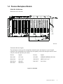
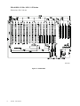
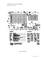
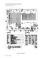
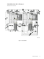
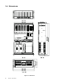
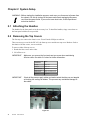
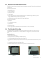
IPC-623 Series
20-slot 19" Rackmount
Industrial PC Chassis
User's Manual
Copyright Notice
This document is copyrighted, April 1999, by Advantech Co., Ltd. All rights are reserved.
Advantech Co., Ltd. reserves the right to make improvements to the products described in this manual
at any time without notice.
No part of this manual may be reproduced, copied, translated or transmitted in any form or by any
means without the prior written permission of Advantech Co., Ltd. Information provided in this manual
is intended to be accurate and reliable. However, Advantech Co., Ltd. assumes no responsibility for its
use, nor for any infringements of the rights of third parties which may result from its use.
Acknowledgments
The IPC-623, PCA-6120, PCA-6120P4, PCA-6119P7, PCA-6119P10, PCA-6119P17, PCA-6120D,
PCA-6120DP4, PCA-6118DP7, PCA-6120Q and PCA-6116QP2 are trademarks of Advantech Co., Ltd.
Note:
The information in this document is provided for reference only. Advantech Co.,
Ltd. does not assume any liability arising out of the application or use of the
information or products described herein. This manual is subject to change
without notice.
Part No. 2002062300
1st Edition Printed in Taiwan April 1999
ii
IPC-610 User's Manual
Contents
Chapter 1 General Information .................................................. 1
1.1 Introduction .............................................................................................................. 1
1.2 Specifications .......................................................................................................... 1
General ................................................................................................................................................................ 1
Environmental Specifications .............................................................................................................................. 2
1.3 Passive Backplane Options ..................................................................................... 2
1.4 Passive Backplane Models ...................................................................................... 3
PCA-6120: 20 ISA slots ...................................................................................................................................... 3
PCA-6120P4: 15 ISA / 4 PCI / 1 CPU slots ........................................................................................................ 4
PCA-6119P7: 11 ISA / 7 PCI / 1 CPU slots ........................................................................................................ 5
PCA-6119P10: 8 ISA / 10 PCI / 1 CPU slots ...................................................................................................... 6
PCA-6119P17: 1 ISA / 17 PCI / 1 CPU slots ...................................................................................................... 7
PCA-6120D: 10 ISA slots x 2 ............................................................................................................................. 8
PCA-6120DP4: 5 ISA / 4 PCI / 1 CPU slots x 2 ................................................................................................. 9
PCA-6118DP7: 5 ISA slots x 4 ......................................................................................................................... 10
PCA6120Q: 5 ISA slots x 4 ............................................................................................................................... 11
PCA-6116QP2: 1 ISA / 2 PCI / 1 CPU slots x 4 ............................................................................................... 12
1.5 Power Supply ........................................................................................................ 13
300 watt redundant power supply ...................................................................................................................... 13
400 watt single power supply ............................................................................................................................ 13
1.6 Dimensions ............................................................................................................ 14
1.7 Exploded diagram .................................................................................................. 15
Chapter 2 System Setup ......................................................... 16
2.1 Attaching the Handles ........................................................................................... 16
2.2 Removing the Top Covers ..................................................................................... 16
2.3 Chassis Front and Rear Sections .......................................................................... 17
2.4 The Standard Drive Bay ........................................................................................ 17
2.5 Four Models of the IPC-623 .................................................................................. 18
2.5.1 The redundant power supply model ......................................................................................................... 18
2.5.2 The single power supply model ................................................................................................................ 19
2.5.3 The 14-slot system model ......................................................................................................................... 20
2.5.4 The ATX motherboard system model ....................................................................................................... 20
2.6 LED Indicators ....................................................................................................... 21
2.7 Front Panel Switches ............................................................................................. 22
2.8 Cooling Fans ......................................................................................................... 22
2.9 Alarm Board........................................................................................................... 22
IPC-610 User's Manual
iii
2.10 Temperature Sensors ............................................................................................ 23
2.11 Filters ..................................................................................................................... 24
2.12 CPU Cards and Add-on Cards .............................................................................. 24
2.13 Hold-down Clamp .................................................................................................. 24
Appendix A Jumper and Connector Settings .................................. 25
A.1 Alarm Board Jumper Settings ................................................................................ 25
A.2 Connectors ............................................................................................................ 25
iv
IPC-610 User's Manual
Chapter 1 General Information
1.1 Introduction
The IPC-623 is a 4U 19" rackmount chassis that is ideal for CTI applications, as well as industrial
automation systems.
The IPC-623 can hold either a single IPC system or multi-systems, and can be configured with a 300 W
redundant power supply or a 400 W single power supply. A 20-slot PCI/ISA backplane fits easily, as
well as a wide variety of multi-segment PCI/ISA or ISA backplanes. Outstanding features include a
drive bay that holds three half-height drives and one 3.5" floppy drive, with space for another 3.5" hard
drive inside the chassis.
In addition, the IPC-623 also features advanced fault resilient capabilities. Power failure, fan failure or
overheating activates an audible alarm to notify that immediate maintenance is necessary.
1.2 Specifications
General
• Construction: Heavy-duty steel chassis
• Drive bay: Three front accessible half-height drives. One hard drive, one 3.5" floppy drive, and an
additional internal 3.5" hard drive. Shock and vibration damped by four mounted cushions
• Cooling system: Three 85 CFM, hot-swappable cooling fans (inward flow), 120 x 120 x 25 mm each
• Controls: Power on/off switch, alarm reset switch, and system reset switch
• Indicators: Bi-color LED (green/red) for power failure
Bi-color LED (green/red) for any type of fan failure
Bi-color LED (green/red) for overheating
Single-color LED (green) for HDD activity
Single-color LEDs (green) for power source (+5 V, -5 V, +12 V, and -12 V)
• Two top covers: a) front top cover for drive bay & cooling fan maintenance
b) rear top cover for CPU add-on card maintenance
• Ventilation: Behind front panel on both sides
• Slide rails: General Device C-300 series supported
• Chassis color: Black 2U 2X, 2C 2X or PANTONE 414U
• Dimensions (W x H x D): 482 x 177 x 660 mm (19" x 7" x 26")
• Weight: 26 kg (57 lbs)
IPC-623 User's Manual
1
Environmental Specifications
• Operating temperature: 0 ~ 45° C (32 ~ 113° F)
• Relative humidity: 10 ~ 95% @ 40° C, non-condensing
• Shock resistance: 30 G acceleration, peak to peak, 11 ms (non-operating)
10 G acceleration peak to peak, 11 ms acceleration peak to peak (operating)
• Vibration: 5 ~ 500 Hz, 0.5 G sine wave, and 5 ~ 500 Hz, 1 G (rms.) random
• Safety: CE compliant, C-UL approved
1.3 Passive Backplane Options
Single segment backplane models
• PCA-6120:
20 ISA slots
• PCA-6120P4: 15 ISA / 4 PCI / 1 CPU slots
• PCA-6119P7: 11 ISA / 7 PCI / 1 CPU slots
• PCA-6119P10: 8 ISA / 10 PCI / 1 CPU slots
• PCA-6119P17: 1 ISA / 17 PCI / 1 CPU slots
Multi-segment backplane models
Two segments
• PCA-6120D:
10 ISA slots x 2
• PCA-6120DP4: 5 ISA / 4 PCI / 1 CPU slots x 2
• PCA-6118DP7: 1 ISA / 7 PCI / 1 CPU slots x 2
Four segments
• PCA-6120Q:
5 ISA slots x 4
• PCA-6116QP2: 1 ISA / 2 PCI / 1 CPU slots x 4
2
IPC-623 User's Manual
1.4 Passive Backplane Models
PCA-6120: 20 ISA slots
Dimensions: 420 x 200 mm
Unit: mm
Termination Resistor Signals
The termination resistors provide an impedance mismatch at the end of the bus to prevent signal
reflections. This mismatch has to be balanced by the capability of the CPU and option cards to electrically drive the load imposed by the resistor.
Resistor
Signals
Resistor
Signals
RN1, RN8
SA7-SA0
RP1, RP2
SMEMW, SMEMR, IOW, IOR
RN4, RN11
SA15-SA8
RN2, RN12
SBHE, LA23-LA17
RN5, RN10
SD0-SD7
RN6, RN7
SA19-SA16
RN3, RN9
SD8-SD15
Figure 1-1: PCA-6120
IPC-623 User's Manual
3
PCA-6120P4: 15 ISA / 4 PCI / 1 CPU slots
Dimensions: 420 x 260 mm
Unit: mm
Figure 1-2: PCA-6120P4
4
IPC-623 User's Manual
PCA-6119P7: 11 ISA / 7 PCI / 1 CPU slots
Dimensions: 260 x 417 mm
Unit: mm
Figure 1-3: PCA-6119P7
IPC-623 User's Manual
5
PCA-6119P10: 8 ISA / 10 PCI / 1 CPU slots
Dimensions: 260 x 417 mm
Unit: mm
Figure 1-4: PCA-6119P10
6
IPC-623 User's Manual
PCA-6119P17: 1 ISA / 17 PCI / 1 CPU slots
Dimensions: 260 x 417 mm
Unit: mm
Figure 1-5: PCA-6119P17
IPC-623 User's Manual
7
PCA-6120D: 10 ISA slots x 2
Dimensions: 420 x 200 mm
Unit: mm
Termination Resistor Signals
The termination resistors provide an impedance mismatch at the end of the bus to prevent signal
reflections. This mismatch has to be balanced by the capability of the CPU and option cards to electrically drive the load imposed by the resistor.
Resistor
Signals
Resistor
Signals
RN1, RN8
SA7-SA0
RP1, RP2
SMEMW, SMEMR, IOW, IOR
RN4, RN11
SA15-SA8
RN2, RN12
SBHE, LA23-LA17
RN5, RN10
SD0-SD7
RN6, RN7
SA19-SA16
RN3, RN10
SD8-SD15
Figure 1-6: PCA-6120D
8
IPC-623 User's Manual
PCA-6120DP4: 5 ISA / 4 PCI / 1 CPU slots x 2
Dimensions: 420 x 200 mm
Unit: mm
Figure 1-7: PCA-6120DP4
IPC-623 User's Manual
9
PCA-6118DP7: 5 ISA slots x 4
Dimensions: 260 x 417 mm
Unit: mm
Figure 1-8: PCA-6118DP7
10
IPC-623 User's Manual
PCA6120Q: 5 ISA slots x 4
Dimensions: 420 x 200 mm
Unit: mm
Figure 1-9: PCA-6120Q
IPC-623 User's Manual
11
PCA-6116QP2: 1 ISA / 2 PCI / 1 CPU slots x 4
Dimensions: 260 x 417 mm
Unit: mm
Figure 1-10: PCA-6116QP2
12
IPC-623 User's Manual
1.5 Power Supply
300 watt redundant power supply
Output rating: 300 W maximum
Input voltage: 90/180 ~ 132/264 VAC @ 47 ~ 63 Hz
Output voltage: +5 V @ 30 A, +12 V @ 12 A, -5 V @ 0.5 A, -12 V @ 1 A
Min. load: +5 V @2 A, +12 V @ 1 A
MTBF: 100 K hours
Safety: UL/CSA/TUV/CE
EMI: FCC part 15 class B, CISPR 22 class B, VCCI class 2
400 watt single power supply
Output rating: 400 W maximum
Input voltage: 100/200 ~ 130/260 VAC @ 47 ~ 63 Hz
Output voltage: +5 V @ 40 A, +12 V @ 20 A, -5 V @ 0.5 A, -12 V @ 1 A
Min. load: +5 V @ 3 A, +12 V @ 0.5 A
MTBF: 150 K hours
Safety: UL 1950, CSA E.B. 1420C
EMI: FCC part 15, CISPR 22 class A
IPC-623 User's Manual
13
1.6 Dimensions
Figure 1-11: Dimensions
14
IPC-623 User's Manual
1.7 Exploded diagram
UPPER COVER 2
UPPER COVER 1
HOLD-DOWN CLAMP
REDUNDANT POWER SUPPLY ASSEMBLY
RUBBER HOLDER
I/O SPRING PLATE
BACKPLANE
FAN ASSEMBLY
DISK DRIVE ASSEMBLY
BACKPLANE BRACKET
FAN
TEMPERATURE SENSOR PCB
TEMPERATURE SENSOR PCB
I/O BRACKET
ALARM PCB
ALARM PCB
CHASSIS
ROCKET SWITCH
EMI FILTER BRACKET
FILTER
POWER MOUNTING
FILTER COVER
REDUNDANT POWER SUPPLY
CUSHIONING BRACKET
FILTER COVER
DISK DRIVE
POWER BRACKET
LED COVER
LED BRACKET
RACK MOUNTING EAR
PANEL BRACKET
LED PCB
DOOR
FILTER COVER
FILTER
LED LABEL
Figure 1-12: Exploded diagram
IPC-623 User's Manual
15
Chapter 2 System Setup
WARNING: Before starting the installation process, make sure you disconnect all power from
the chassis. Do this by turning off the power switch and unplugging the power
cord from the power outlet. If you are not sure what to do, let an experienced
technician handle it.
2.1 Attaching the Handles
The handles for the front panel are in the accessory box. To install the handles, simpy secure them to
the front panel with the screws provided.
2.2 Removing the Top Covers
The first step is to remove the chassis cover. You will need a Philips screwdriver.
There are two top covers for the IPC-623: the front top cover and the rear top cover. Both are fixed to
the chassis with four screws, two on each side.
To remove either of the top covers:
1. Detach the four screws on the sides.
2. Lift off the cover.
IMPORTANT:
Make sure you remove the front and rear top covers when maintaining
full-size cards. See table 2-1 below for further information:
Component in need
of maintenance
IMPORTANT:
Remove
Drive bay
front top cover
Cooling fan
front top cover
Half-size CPU card
rear top cover
Full-size CPU card
front top cover & rear top cover
Full-size I/O card
front top cover & rear top cover
Alarm board
rear top cover
Check all the power supply cables and make certain that they are not tangled
or blocking the cooling fan blades. This prevents any accidental damage to
the cables.
Figure 2-1
16
IPC-623 User's Manual
2.3 Chassis Front and Rear Sections
The IPC-623 comes in two sections: the front section and the rear section. Each of these sections has its
own top cover.
The front section includes:
1. Standard drive bay.
2. Three cooling fans.
3. Front chassis door.
4. Control panel.
5. Power supply (two power supply modules for the Power Redundant Supply Model; one power
supply module for the Single Power Supply Model).
6. Additional drive bay (for the Single Power Supply Model only).
The rear section includes:
1. Backplane.
2. Two temperature sensors.
3. Alarm board.
4. Hold-down clamp.
5. Power supply (for the ATX Motherboard System and the 14-slot System Model).
2.4 The Standard Drive Bay
The standard drive bay of the IPC-623 can hold up to three front accessible 5.25" drives, such as a
CD-ROM unit, a removable drive, a vertically mounted 3.5" floppy drive, or an internal 3.5" hard
drive.
Installing disk drives
1. Remove the top front cover.
2. Detach the four screws holding the standard drive bay.
3. Lift off the standard drive bay (please refer to figure 2-3).
4. Insert the drives into their proper locations in the drive bay and secure them with the screws provided.
5. Connect the disk drive power and signal cables.
6. Install the standard drive bay and secure the top front cover with the four screws.
Figure 2-2
Figure 2-3
IPC-623 User's Manual
17
2.5 Four Models of the IPC-623
Advantech supplies four IPC-623 models.
2.5.1 The redundant power supply model
In this configuration, the power supply is installed in the front section of the chassis. The 300 W
redundant power supply comes in two modules, which are located at the left side of the front section.
Figure 2-3-a
Figure 2-3-b
Both modules are hot-swappable and are accessible from the front. Please refer to figures 2-3-a and
2-3-b.
The standard drive bay is at the right side of the front section. Please see section 2.4 for further details.
The backplane is installed at the rear.
Replacing the power supply module
To remove a redundant power supply module:
1. First check that the chassis door is open wide - either to the horizontal or inclined downward.
2. Unlock the power supply module.
3. Flip the power supply module toward yourself.
4. Grab the handle and gently pull out the power supply module (see figure 2-5).
Figure 2-4
18
IPC-623 User's Manual
Figure 2-5
WARNING: Do not remove the power supply module if the front chassis door is not opened
completely. Removing the power supply module in such a way might result in
damage of your chassis. See figure 2-6.
Figure 2-6: Do not do this!
Replacing the redundant power supply module:
1. Make sure that the power supply module is the same rating as the one currently installed.
2. Open the front chassis door as wide as you can. See figures 2-4 and 2-5.
3. Slide the power supply module inward until it locks into place.
4. Flip back the power supply module handle toward the chassis.
2.5.2 The single power supply model
Figure 2-6-a
Figure 2-6-b
With this configuration, there is only one single 400 W AT power supply. It is hidden inside the front
section of the chassis, at the left. With only one power supply module installed, an additional drive bay
can be installed next to that power supply. Six 3.5" hard drives can be installed in this internal drive
bay. Please see figures 2-6-a and 2-6-b.
At the right is the standard drive bay. Refer to section 2.4 for a more detailed description. Installed at
the rear section is the backplane.
IPC-623 User's Manual
19
Installing an HDD into the drive bay:
1. Undo the four screws of the drive bay.
2. Align the hard drive with its proper position.
3. Fix the screws into the screw holes on the sides of the drive bay.
4. Connect the disk drive power and signal cables.
2.5.3 The 14-slot system model
Figure 2-6-c
Figure 2-6-d
This model features a 14-slot backplane and a power supply module fitted at the rear section of the
chassis.
The front section has two standard drive bays, which allows installation of up to six 5.25" drives
(CD-ROM, removable drive), two 3.5" floppy drives, and two internal 3.5" hard drives. See figures
2-6-c and 2-6-d.
Please refer to section 2.4 for installing the drives in the standard drive bay.
2.5.4 The ATX motherboard system model
Figure 2-6-e
20
IPC-623 User's Manual
Figure 2-6-f
This model allows an ATX motherboard with ATX power supply alongside, both of which are fitted at
the rear section. Refer to figure 2-6-e.
The front section is equipped with two standard bays, which enables installation of up to six 5.25"
drives (CD-ROM, removable drive), two 3.5" floppy drives, and two internal 3.5" hard drives. See
figure 2-6-f.
For installing the drives in the standard drive bay, refer to section 2.4.
2.6 LED Indicators
The front chassis door contains a series of LED indicators, which are grouped into two categories.
System Status LEDs
These LEDs show the current status of critical elements and parameters within the chassis.
LED
Description
Red light
(blinking)
Green light
(constant)
PWR
system power
not normal
normal
HDD
hard drive activity
no light
data access
FAN
cooling fan status
not normal
normal
TEMP
chassis
temperature
not normal
normal
A failed cooling fan triggers a blinking red FAN LED, and also an alarm. In order to stop the alarm,
you have to press the alarm reset button. Then replace the fan immediately. Please see section 2.7 for
further information.
If the TEMP LED is blinking red, the system has detected excessive temperature inside the chassis. An
audible alarm is triggered, which can be switched off by pressing the alarm reset button. Refer to
section 2.7. Inspect the rear section immediately and make sure that airflow inside the chassis is smooth
and free from dust or other particles.
Power Status LEDs
These LEDs indicated the status of the backplane voltage signals.
LED
Description LED on
LED off
+5 V
+5 V signal
normal
abnormal
+12 V
+12 V signal normal
abnormal
-5 V
-5 V signal
normal
abnormal
-12 V
- 12 V signal normal
abnormal
When an LED fails to light up, it means there is a problem with one of the voltage signals. When this
happens, an audible alarm sounds. Check if the power supply connector is properly attached to the
backplane. If the problem persists, consult an experienced technician.
IPC-623 User's Manual
21
2.7 Front Panel Switches
The front panel switches are used for system power, system reset and alarm reset.
Power On/Off Switch
Used for switching the system power on or off.
System Reset Switch
Reinitializes the system. This switch is similar to the hardware reset button.
Alarm Reset Switch
For suppressing or stopping an audible alarm. Whenever a fault in the system
occurs (e.g. fan failure, overtemperature, improper backplane voltage), an
audible alarm is activated. Pressing this button will cause the alarm to stop.
2.8 Cooling Fans
Three cooling fans are located within the chassis. All of them are hot-swappable and provide the
system with ample cooling by blowing air inward. When a cooling fan shuts down, the system will
sound a continuous alarm. To turn the alarm off, press the alarm reset switch on the front panel. However, you will have to replace the failed fan immediately.
Replacing the cooling fan
1. Loosen the fixed screw located on top of the fan unit.
2. Use the screw to pull out the fan unit.
3. Replace the cooling fan.
4. Tighten the screw in order to secure the cooling fan unit.
Figure 2-8
Figure 2-9
2.9 Alarm Board
The alarm board is located in the rear section, between the cooling fan and the backplane. It gives an
audible alarm when:
a. One of the cooling fans fails
b. Temperature inside the chassis rises to an excessive level
c. A problem occurs in one of the backplane voltage levels
To stop this continuous alarm, press the alarm reset switch at the front panel. Please see the appendix
for further details.
22
IPC-623 User's Manual
2.10 Temperature Sensors
There are two temperature sensors inside the chassis. They are located at the rear section, attached to
the left and right upper corner of the chassis backplate. Refer to figure 2-10.
When the temperature rises, the sensors send a signal to the alarm board, and a continuous alarm is
sounded. To stop the alarm, press the alarm reset switch at the front panel.
Figure 2-10
Adjusting the temperature sensors
The temperature sensors can only be adjusted during installation of the CPU cards and add-on cards. If
you encounter difficulties when installing the cards because of the location of the temperature sensors,
you should do the following:
1. Remove the screw which secures the temperature sensor to the chassis.
2. Move the sensor away from its location. See figure 2-11.
3. Insert the card into the slot.
4. Return the temperature sensor back to its original location.
5. Re-attach the screw.
Figure 2-11
IPC-623 User's Manual
23
2.11 Filters
There are four filtered ventilation holes, two on each side of the chassis. In addition, the fan filter is
protected with a metal bracket.
Replacing the fan filters:
1. Loosen the two screws that hold the metal bracket in place.
2. Remove the metal bracket.
3. Remove the filter, which you should either rinse with water or dispose of properly.
4. Use a new filter to replace the old one, or put the clean filter back. Make sure the filter is dry.
5. Return the metal bracket back to its original position.
6. Secure the bracket with the two screws.
2.12 CPU Cards and Add-on Cards
Installing slot-board computers and other add-on boards:
1. Remove the chassis cover. Please refer to section 2-2.
2. Remove the slot cover.
3. If the temperature sensor becomes an obstacle for installing the card, see section 2.10 on adjusting
the sensor location.
4. Insert the CPU card or add-on card vertically into the vacant slot. See figure 2-11-a.
5. Align and tighten the screws to secure the card in a fixed position. Refer to figure 2-11-b.
Figure 2-11a
Figure 2-11b
2.13 Hold-down Clamp
The IPC-623 uses a hold-down clamp to secure the cards. This protects the cards against vibration and
shocks. After inserting the CPU card and add-on cards, remember to install the hold-down clamp.
Installing the clamp:
1. After plugging in the add-on cards, insert the provided rubber buffers into the hold-down clamp so
that their positions correspond with the locations of the cards. These buffers offer the plug-in cards
two levels of protection against shocks and vibration.
2. Place the hold-down clamp in its original position.
3. Secure the screws.
24
IPC-623 User's Manual
Appendix A Jumper and Connector Settings
A.1 Alarm Board Jumper Settings
J1, J2, J3: MB and B/P Selection
Function
B/P version
Jumper Settings
J1, J2: 2-3 closed; J3: open (Default)
MB version
J1, J2: 1-2 closed; J3: closed
J4: +3.3 V Detection
Function
Disabled
Jumper Setting
J4: open (Default)
Enabled
J4: closed
J5, J6: Fan Alarm Selection
Function
FAN1 ~ FAN3 All Enabled
Jumper Settings
J5: open; J6:open (Default)
FAN1 and FAN3 Enabled
J5: closed; J6:open
One FAN Enabled
J5: closed; J6:closed
J7: Temperature Alarm Selection
Function
TEMP1 and TEMP2 Enabled
Jumper Setting
J7: open (Default)
TEMP1 or TEMP2 Enabled
J7: closed
A.2 Connectors
Number Function
CN1
Main power connector
CN2
External speaker pin header
CN3
FAN3 connector
CN4
FAN2 connector
CN5
FAN1 connector
CN6
Front panel LED connector
CN7
14-slots B/P connector
CN8
20-slots B/P connector
CN9
TEMP2 connector
CN10
TEMP1 connector
CN11
Alarm buzzer reset pin header
CN12
Power fail signal connector
CN13
HDD1/HDD2 LED pin header
IPC-623 User's Manual
25