1
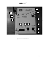
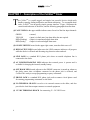
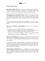
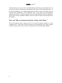
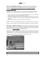
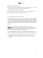
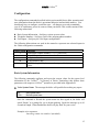
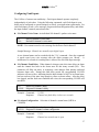
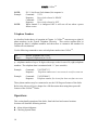
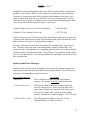
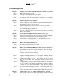
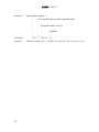
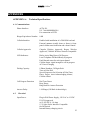
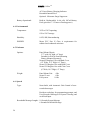
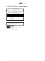
MICROTEL CellStat
TM
Microtel CellStatTM
Operating Manual
28 December 2006
Rev. -
Proprietary Notice: This document and the subject matter hereto are the
property of MICROTEL, Inc. and shall not be reproduced or copied or used for the
purpose of manufacturing or sale of apparatus, except by written permission of
MICROTEL.
MICROTEL
11725 Sunbelt Court
Suite C
Baton Rouge, LA 70809
225-303-0436
Fax: 225-303-0568
www.microtel-inc.com
MICROTEL CellStat
TM
Record of Changes
Rev.
-
ii
Date
12/28/06
Description of Changes
Original Release
By
Art Felgate
MICROTEL CellStat
TM
TABLE OF CONTENTS
INTRODUCTION
2
CHAPTER 1 -
DESCRIPTION OF THE CELLSTATTM DIALER
4
CHAPTER 2 -
INSTALLATION
9
Quick Start Procedure
CHAPTER 3 -
OPERATION
12
14
Configuration
Basic System Information
Configuring Fault Inputs
Telephone Numbers
15
15
17
18
Operations
Alarm Acknowledgment
Checking System Status
18
19
19
CHAPTER 4 -
MAINTENANCE/TROUBLESHOOTING
Spoken Fault/Error Messages
CHAPTER 5 -
ADVANCED TOPICS
Advanced Configuration Options
APPENDICES
20
21
23
23
25
APPENDIX A:
Technical Specifications
25
APPENDIX B:
Glossary of Dialer Terminology
28
APPENDIX C:
FCC Requirements
29
APPENDIX D: CellStatTM Command Summary
30
LIST OF ILLUSTRATIONS
Figure 1:
Figure 2:
Figure 3.
Figure 4:
Figure 5:
Controls and Indicators................................................................................2
Power Supply Connection ...........................................................................8
External Cellular Antenna Connector…………………………………….. 10
I/O Terminal Connections ...........................................................................11
Mounting dimensions ..................................................................................31
1
MICROTEL CellStat
TM
INTRODUCTION
hank you for choosing the Microtel CellStatTM Dialer to implement your remote
alarm monitoring solution. You have chosen a product that is simple to set up and
easy to use. CellStatTM has been designed and manufactured to operate with
minimal operator intervention.
T
The Microtel CellStatTM features a single level, interactive command structure--there are
no multi-level menu structures to navigate. Commands are sent to the dialer through your
telephone either locally or during a call to or from the dialer, by pressing a sequence of
touch-tones on your telephone. Each command entered is acknowledged with a spoken
response from CellStatTM, providing verification that the command was entered correctly
and understood by the dialer.
About this Manual: This manual is organized with the most crucial information in
the front; more advanced topics are saved for last or included in the appendices.
Who Should Read this Manual: Anyone involved with use of the dialer should
read the General Description and Operation chapters of the manual. The Operation
chapter in particular should be read by any personnel who may be required to respond to
alarm calls from the dialer. The additional chapters can be read at a later time, or when
necessary by authorized personnel to maintain the dialer or troubleshoot any problems
you might encounter. System administrators should read the Advanced Topics chapter
for information on the use of the dialer’s remote software configuration capabilities.
In a Hurry to Setup? Read the Quick Start section of the Installation chapter.
If you encounter a difficulty that cannot be resolved using the information in the manual,
call MICROTEL at (225) 303-0436.
Again, thank you for choosing MICROTEL.
2
MICROTEL CellStat
TM
11
2
12
10
9
1
8
6
7
5
3
4
Figure 1: Controls and Indicators
3
MICROTEL CellStat
TM
CHAPTER 1 - Description of the CellStatTM Dialer
he CellStatTM is a small, rugged, and simple, but powerful, device which easily
handles complex dialing notification and alarm monitoring. To accomplish these
tasks, CellStatTM has an equally simple operator interface. Figure 1 illustrates the
controls and indicators of the dialer, and the following paragraphs describe them.
T
(1) FAULT LEDS in the upper middle indicate status for each of the four input channels:
GREEN
YELLOW
RED (Flashing)
RED (Steady)
= normal,
= input is in fault state, but alarm delay has not expired.
= Input is in unacknowledged alarm state
= Input is in acknowledged alarm state
(2) ON/OFF SWITCH located in the upper right corner, turns the dialer on or off.
(3) RING/ACTIVE LED located adjacent to the LINE connector indicates call progress
while the dialer is off-hook and incoming ring detection when on-hook.
(4) LINE JACK is a standard RJ11 phone jack where an outside telephone line is
connected to the dialer.
(5) AC POWER/CHARGING LED indicates that external power is present and is
available for charging the internal, standby battery.
(6) OFF HOOK LED located adjacent to the PHONE connector is turned on whenever
the dialer senses that a telephone connected to the phone jack is off-hook, and
CellStatTM is ready to accept programming or query commands.
(7) PHONE JACK is a standard RJ11 phone jack used to connect a local phone--used
for entering programming commands--to the dialer.
(8) I/O TERMINAL BLOCK is used to wire external sensors to the dialer, and also
provides the local alarm output contacts to external equipment.
(9) 12 VDC TERMINAL BLOCK for connecting 12 – 20 VDC Power.
4
MICROTEL CellStat
TM
(10) CELLULAR STATUS LED indicates cellular signal strength or call in-progress:
BLINK (Rapid)
= Cellular initialization in progress
1 BLINK (Very brief) = Cellular signal strength unknown or not detectable
1 BLINK (Long)
= Weak cellular signal strength
2-3 BLINK
= Normal cellular signal strength
3-5 BLINK
= Strong cellular signal strength
ON STEADY
= Cellular call in progress
The Cellular Status indication LED will repeat its pattern after 5 seconds of OFF
time.
(11) CELLULAR VOLUME CONTROL for adjusting volume of speech heard via the
cellular connection. Turn clockwise to increase volume while listening to the dialer
over the cellular connection. (NOTE: This control has NO effect on the volume of
speech heard via the PHONE or LINE telephone connections)
(12) CELLULAR ANTENNA/CONNECTION for attaching either a cellular antenna,
or an extension cable to a remote antenna.
5
MICROTEL CellStat
TM
Theory of Operation
How Does the Dialer Work? This section provides a simple theory of operation by
asking a few questions about typical use of the dialer. The following paragraphs assume
the dialer is hooked up and running as described in the Installation chapter. The
Operation chapter provides the details that are missing from the discussion below.
What Happens when an Alarm Occurs? CellStatTM has a telephone directory of
up to eight people, answering machines, or pagers to call in the event of an alarm. When
an alarm occurs, the dialer begins to place a series of telephone calls over the telephone
line or built-in cellular module, or both, in an attempt to have someone acknowledge the
alarm.
The dialer reports the current alarm status when an outgoing call is answered. It repeats
the message several times while listening for a touch-tone being entered on the remote
phone.
How does an Alarm get Acknowledged? An alarm can be acknowledged in
three ways:
1) Entering the '*' key on your touch-tone phone during message playback.
2) Calling back the dialer immediately after it calls you (callback acknowledge). This
feature is necessary if the called party does not have a touch-tone phone.
3) The dialer will automatically acknowledge a successful call to a pager, answering
machine, or P.A. system if the telephone number is embedded with an auto
acknowledge code. (See chapter 5, Advanced Topics).
What if I’m not Home? The Call Progress Decoding features of the dialer allow it
to determine if the called telephone number is busy or did not answer. In either case, the
dialer will wait 10 seconds before going off-hook and placing a call to the next number
on the calling list.
When the dialer is off-hook, it has the capability to detect dial tone, busy, ringback, and
voice signals. This allows it to detect if a called party answered or not, thus reducing the
time to alert authorized personnel of existing alarm conditions. If a call is not answered,
or the called number is busy, the dialer will abort the call and begin calling the next
number on the system telephone list.
Will the Dialer Call Me Back? Maybe. The dialer has a snooze timer. When an
alarm is acknowledged, the snooze timer is started, and alarm calls for all acknowledged
faults are suspended. If a channel is still in alarm after the snooze period ends, then the
dialer will begin a new alarm dialing sequence (starting with the first number on the
telephone list).
6
MICROTEL CellStat
TM
How does the Dialer Know Who to Call? The dialer has a System Telephone
Directory composed of up to 8 user-programmed telephone numbers. Each telephone
number in the System Telephone Directory can be up to 30 digits long, and can specify
tha the call is placed over the hardwired telephone line or via the built-in cellular module.
Special ‘*’ control sequences may be embedded within a user-programmed telephone
number. These include tone/pulse selection dialing, pauses, auto acknowledgment of an
alarm call-out, dial '*' or '#' for interfacing to telephone equipment, or to select the builtin cellular capability to make the call. These special sequences allow a tremendous
amount of flexibility on a telephone number by number basis. For example, one number
may use the hard-wired telephone connection, while another may use the built-in cellular
module.
How does the Dialer Prioritize its Calls?
When the dialer detects a new alarm condition, it will search the telephone directory,
beginning with the first number on the list, for the first valid telephone number. The
dialer will then go off-hook (or use the built-in cellular communications if the phone
number has *7 code indicating the dialer should dial out using the cellular interface) and
begin to dial the telephone number if the following conditions are true:
1. The Call Spacing Timer = 0, and the dialer has been on-hook for at least
the network recovery time (10 seconds).
2. The local telephone is on-hook (OFF HOOK LED is OFF).
3. The telephone line is operational (dial tone is detected), OR, if a cellular call,
there is sufficient minutes balance in the cellular prepaid account to make a call.
During the dial out sequence, the dialer will implement all special control sequences
and/or call progress features embedded within the current telephone number. If the dialer
successfully connects with the called number, it will report the verbal alarm message for
each fault condition which exists.
The dialer will repeat the alarm message five times after a call is answered. While
speaking the alarm message, the dialer simultaneously listens for a touch-tone entered by
the user at the remote phone. If it receives a valid tone, it will terminate alarm reporting,
and examine the tone received. If the user entered a ‘*’ key, the dialer will accept it as an
acknowledgment of the alarm condition. Any other keys received will not acknowledge
the alarm condition. The dialer will then indicate the acknowledge status and prompt the
user to enter a 2-digit access code.
If the user enters the correct code, access will be granted and the user may review or
program the dialer’s configuration using the touch-tone commands described in this
manual. If at any time during remote menu access the user does not enter a command
within 30 seconds, the dialer will speak a disconnect warning and hang up.
7
MICROTEL CellStat
TM
If an incorrect or no access code is entered during a timed access code entry time (10
seconds), the dialer will disconnect and initialize the system Call Spacing delay timer. If
the alarm condition(s) were acknowledged, then the snooze timer(s) associated with the
reported alarm condition(s) will be initialized with a value equal to the programmed
system Snooze Delay. If alarm conditions were not acknowledged, calls will continue to
be placed to the next telephone numbers on the list after the system Call Spacing delay
has expired.
How can I Make an Alarm Sound in the Vicinity of the Dialer?
The local summary alarm contacts will be de-energized (opened) whenever a fault
condition exists. This output could be connected to an interposing relay whose contacts
would be used to switch a siren or bell to warn the local area of the alarm condition.
8
MICROTEL CellStat
TM
CHAPTER 2 - Installation
I
nstallation of the CellStatTM involves several, simple steps. This chapter outlines the
physical connections to the dialer. At the end of this chapter is a Quick Start
procedure which summarizes the configuration procedure of the dialer.
Step One - Connect the Power Supply Connect the supplied external
transformer to the 12 VDC terminals as shown in Figure 2 below. Plug the transformer
into a MicroMax Surge Suppressor (Recommended by Microtel).
Figure 2. Power Supply Connection
NOTE: Alternatively, you may connect any 12 to 20 Volt DC power (such as a solar
panel) to the dialer. Connect the positive side of the voltage source to 12VDC+, and the
COMMON lead to 12VDC- of the power supply terminal block of the dialer.
NOTE: Although the dialer will operate and place telephone calls when operating on its
standby battery, external power must be present whenever you wish to configure/query
the dialer from the local phone PHONE jack.
9
MICROTEL CellStat
TM
Step Two - Telephone Connections (Optional) include the external phone line
for call-outs and the optional local telephone connection for local programming and
monitoring. If only the built-in cellular interface is to be used, then no telephone
connections are necessary.
CAUTION: This equipment cannot report an alarm when other equipment (telephone,
answering system, computer modem, etc.) connected to the same phone line is in use.
1. Connect the dialer’s LINE jack to the EQUIPMENT Phone jack of the MicroMax
Surge Suppressor using the cable supplied with your dialer.
2. Connect the Telephone LINE jack on the MicroMax Surge Suppressor to the RJ11
jack of your outside line using the cable supplied with the MicroMax Surge
Suppressor.
3. Connect a local telephone (optional) to the dialer’s PHONE jack.
NOTE: Telephone line transients and surges can damage the dialer or disrupt its
operation. We recommend use of the MicroMax Surge Suppressor for normal operations.
Step Three - Cellular Connection If using the built-in cellular interface to place
calls to/from the dialer wirelessly, then ensure the antenna is screwed onto the bulk-head
mounted female SMA connector on the upper left-hand-side of the enclosure, shown in
Figure 3 below. Do not over tighten--finger-tighten only!
Alternatively, a remote antenna can be mounted on the external surface of an enclosure
(Required if the dialer is mounted within a metal cabinet), and a female-to-male SMA
extension cable can be screwed to the bulk-head mounted SMA connector, then routed to
the remote antenna. Again, only finger tighten the SMA connections.
Figure 3. External Cellular Antenna Connector
10
MICROTEL CellStat
TM
Step Four - Connect External Input/Output to the Dialer Each Fault input
has a corresponding terminal (1 - 4), and there are two COM terminals. See Figure 4
below. The terminals are large enough to accept two 14 AWG wires, so if more than two
faults are wired, the COM terminals must be shared. The fault sensing circuitry is
transformer and optically isolated from the dialer circuitry, but all faults share the same
COM. Use 22 AWG shielded twisted pair wire when wiring external sensors to the I/O
terminals. Whenever possible, ground the shield at the sensor end only. Sensor control
wires should never share conduit with AC power wiring.
The local alarm contacts are normally energized, and closed. When a user-defined alarm
condition exists these contacts are opened (de-energized). These contacts may be used to
drive a low power (10 volt-amps Max.) resistive load, or as a signal to another piece of
process-monitoring equipment. High power and/or inductive loads must be driven from
an external power relay. The local alarm contacts are suitable for driving a 12 – 48 volt
DC relay coil.
NOTE: Keep I/O runs to a maximum length of 150 ft.
Figure 4. I/O Terminal Connections
11
MICROTEL CellStat
TM
Quick Start Procedure
This procedure outlines the steps to get the CellStatTM dialer operating in a typical
manner with a minimum of programming.
1. Plug the touch-tone telephone into the Dialer PHONE jack.
2. Connect external 12 VDC transformer to dialer power supply terminal block.
NOTE: External power is required in order to configure the dialer from a local
phone.
3. Verify that the AC POWER/CHARGING LED illuminates (green).
4. Turn ON the dialer switch. Wait about 30 seconds for the dialer to complete its power
on initialization sequence. Take the telephone off-hook. The OFF HOOK light
should be illuminated (yellow) indicating the unit is ready to accept touch-tone
commands from the local telephone.
5. Press the # key of your telephone. The Dialer will respond “Ready.”
NOTE: To start over, press the # key and listen for CellStatTM to speak, “Ready.”
6. Enter Telephone Numbers to Call upon Alarm.
z Enter **6np**, where n = 1,2,3,...8, is the dialer’s directory index of telephone
numbers, and p is the actual telephone number (including optional escape codes
of up to 60 digits). Example: The second phone number of the directory is 5551212. Enter **62 5551212**.
z The Dialer will respond, “Telephone number two is 5551212.”
z To cause the dialer to use its built-in cellular communications, enter a *7 at the
beginning of the telephone number.
7. Configure Input Normal States
z Enter **c3n, where c is the I/O channel (numbered 1 to 4 from left to right) and n
= 1 for NORMALLY OPEN, or 0 for NORMALLY CLOSED.
8. Record System and Alarm Voice Messages
System ID Voice Message:
z Enter **01 to record up to a 10 second system voice message. The dialer will
respond “Ready”.
z Speak your message clearly into the handset.
z The dialer will speak back the message after the 10-second recording interval.
z Repeat as necessary until you are satisfied with the recording.
12
MICROTEL CellStat
TM
Individual Channel Alarm Messages:
z Enter **c1 to record an alarm message for a specific I/O channel. (c = 1 to 4 for
the I/O channel of interest). The dialer will respond “Ready”.
z Speak your message clearly into the handset.
z The dialer will speak back the message after the 6-second recording interval
z Repeat procedure for the next I/O channel and message.
9. Verify Configuration Data is saved in the Dialer.
Turn OFF the Dialer’s power switch, wait a few seconds, then turn it ON again.
Verify configuration data has not changed. Enter *00 and listen to the spoken status
report. If you are using the built-in cellular communications of the dialer, ensure that
the spoken status report indicates there is sufficient signal power and prepaid balance.
If the cellular prepaid balance falls below $5, the dialer will place calls to report this
condition.
10. Important: Test the dialer by causing an alarm condition. Verify ALL the
programmed telephone numbers are successfully called in order to ensure the dialer is
operating properly and can successfully report an alarm condition. Periodically,
retest to continue to ensure the dialer is operating correctly.
WHEN PROGRAMMING EMERGENCY NUMBERS AND(OR) MAKING TEST
CALLS TO EMERGENCY NUMBERS OVER THE PUBLIC TELEPHONE LINE:
1) Remain on the line and briefly explain to the dispatcher the reason for the call.
2) Perform such activities in the off-peak hours, such as early morning or late
evenings.
13
MICROTEL CellStat
TM
CHAPTER 3 - Operation
T
his chapter, divided into Configuration and Operation sections, will explain how
to configure the CellStatTM to react to I/O events and how an operator can make
the dialer respond to remote commands. The Microtel CellStatTM features a single
level, interactive command structure--there are no multi-level menu structures to
navigate. Commands are sent to CellStatTM through your telephone either locally or
during a call to or from the dialer, by pressing a sequence of touch-tones on your
telephone. Each command entered is acknowledged with a spoken response from the
dialer, providing verification that the command was entered correctly and understood by
the dialer.
All programming commands (commands that modify dialer configuration or cause an
action to occur) begin with ‘**’ (two stars). All review (report) commands begin with a
‘*’ (single star). After each command is entered, the dialer will respond with a voice
message. Most commands require exactly the same number of keys every time, but some
commands have a variable data length. The end of variable length data commands is
performed with the ‘**’ (two stars).
NOTE: An unwanted command can be terminated at any time by pressing the ‘#’ key.
The dialer will respond, “Ready”, indicating it is ready to accept a new
command.
Throughout this manual, all commands are highlighted for quick reference as follows:
*nn
**nndd
Review item
Configure item
If your telephone line is not yet installed, you can still configure your dialer:
1.
2.
3.
4.
With power to the dialer off, connect the telephone to dialer’s PHONE jack.
Take the telephone off-hook.
Turn ON power to the dialer (external 12 VDC power required)
The telephone should now be connected to the dialer (indicated by the OFF HOOK
LED being ON ).
5. You may now enter any of the touch-tone commands to query/configure the dialer.
6. When you are finished, hang-up. The OFF HOOK LED should turn OFF indicating
that you hung-up.
14
MICROTEL CellStat
TM
Configuration
The configuration commands described in this section modify basic dialer operation and
store information about the dialer’s operational behavior in nonvolatile memory. You
should only have to configure your dialer once -- all changes are saved permanently,
even if AC and battery power are removed from your dialer. This section consists of the
following subsections:
z Basic System Information - Set/Query various system values
z Telephone Numbers - Set/Query each of the outgoing phone numbers
z Fault Inputs - Set/Query the Faul Input configurations
The following abbreviations are used in the manual to represent user-selected inputs in
the Dialer configuration commands:
Abbreviation
c
~
n
nn
p
Meaning
Fault Input Channel Number, 1-5 (5 = power-fail)
Recorded speech
1 digit numeric data
2 digit numeric data
Variable length Telephone number (up to 30 digits) with escape
codes
Basic System Information
The following commands configure and report the current values for the system level
information of the CellStatTM. A Glossary of Dialer Terminology that defines these
parameters with respect to CellStatTM operation is provided in the Appendix B.
z Voice System Name The message the dialer will speak before making any report.
*01
**01~
Play system name
Record system name
Once the command to Record the system name has been typed in, the dialer will
speak “Ready” as a prompt for you to begin speaking. Speak the message up to 10
seconds in length. When finished the dialer will play back for your review.
Example voice responsesJonesburg remote site number 6 (recorded)
15
MICROTEL CellStat
TM
z Answer Delay The number of rings the dialer will see before answering an incoming
call on the telephone line.
*02
**02nn
Review answer delay
Program answer delay
Example- Command:
Response:
**0205
The telephone answer delay is zero five rings.
z Access Code This 2 digit access code is required to access configuration commands
during a telephone call to or from the dialer.
*03
**03nn
Review value of access code
Program access code
NOTE: The factory set default code is ‘12’. Use a 00 access code value to disable
access code requirement. Access code is not required to configure the dialer through
the local PHONE jack.
Example- Command:
Response:
**0313
The access code is one three.
z Snooze Delay The snooze delay is the time, in hours, after which the dialer will rearm an acknowledged alarm and begin calling again as a reminder that the alarm
condition still exists.
*04
**04HH
Review snooze delay time interval
Program snooze delay time interval
Example- Command:
Response:
**0412
The snooze delay is one two hours.
z Firmware Version
*05
Report Firmware Version
Response will play back all resident vocabulary, then speak “Cell Stat number one zero”,
where “one zero” is the current Firmware version (e.g. 1.0).
16
MICROTEL CellStat
TM
Configuring Fault Inputs
The CellStatTM features true modularity—Fault input channels operate completely
independently of each other. Using the following commands, each Fault Input in your
dialer can be configured to operate uniquely to satisfy your application requirements. For
each Fault Input, record a voice message, program an alarm integration delay, and define
the input channel’s normal (non-alarm) state.
z I/O Channel Voice Name An individual I/O channel’s spoken voice name.
*c1
**c1~
Play I/O channel c voice name
Record I/O channel c voice name
NOTE: User cannot record a voice message for the Power Fault channel 5
Sample Message- Channel one normally open digital input.
A new channel name can be recorded with the '**c1' command. Once the command
is typed record your voice message after the dialer prompts you “Ready”. A
maximum of 6 seconds of recording time is allowed for each fault input message.
z I/O Channel Fault Delay When channel c changes state, this timer delays an alarm
until the channel has been in the alarm state for this many seconds (SS). This
parameter will filter out noisy, or temporary, state changes from placing undesired
nuisance alarm calls. During this fault delay period, the corresponding CH LED
indicator will turn yellow, indicating that the input channel is NOT in its normal state,
but has not been in the state long enough to cause an alarm callout. After the delay
has elapsed, and the fault state condition still exists, the corresponding CH LED will
turn RED.
*c2
**c2SS
Report I/O channel c delay
Program I/O channel c delay
Example- Command:
Response:
**1230
Channel one fault delay is three zero seconds.
z I/O Alarm Configuration Selection of channel c normal state (OPEN or
CLOSED)
*c3
**c31/0
Review I/O channel c alarm configuration
Program I/O channel c alarm configuration
Example- Command:
Response:
**131
Channel one normal state is open
17
MICROTEL CellStat
NOTE:
Example
NOTE:
TM
If C=5, the Power Fault channel, the response is:
Command:
**531
Response:
Power fault channel is READY
Command:
**530
Response:
Power fault channel is OFF
When channel 5 is configured OFF it will not call out when a power
failure occurs
Telephone Numbers
As described in the theory of operation in Chapter 1, CellStatTM can store up to eight (8)
phone numbers in the System Telephone Directory. This section explains how to
program the dialer’s telephone numbers and shows how to customize the numbers for
certain call-out situations.
Use the following command to enter each telephone number into CellStatTM:
*6n
**6np**
Review Telephone n (n=1 to 8)
Program Telephone n (n=1 to 8)
p = telephone number of up to 30 digits with escape codes for one of 8 (eight) telephone
numbers. The telephone data is terminated with ‘**’ (two asterisks).
Example-
Command:
Response:
**612760571**
Telephone number one is two seven six zero five seven one
Example-
Command:
Response:
**652432400**
Telephone number five is two four three two four zero zero
These phone numbers may be customized to use the Call Progress features of the dialer.
Refer to the Advanced Topics chapter for a full discussion about using these powerful
features of the CellStatTM Dialer.
Operations
This section details operation of the dialer, from both local and remote locations.
Sections will detail the following actions:
z Alarm Acknowledgment
z Checking System Status
18
MICROTEL CellStat
TM
Alarm Acknowledgment
When CellStatTM calls you, you may wish to respond to the call differently depending on
what type of alarm has occurred, who is on duty, the time of day, severity of the alarm,
etc.
If you wish the dialer to go to the next phone number on its calling list, hang up the
phone. The dialer will continue on after the call spacing delay to the next phone number
on the list until it receives an acknowledgment or the unlatched alarm goes away by
itself.
If you wish to acknowledge the call from your touch-tone phone, press the ‘*’ key on
your telephone while the alarm message is being spoken. The dialer will respond by
reporting that the alarms are acknowledged. If you then need access to the remote
programming commands, enter the 2 digit access code when CellStatTM prompts you.
After gaining access to the dialer, you may review or modify any of the dialer’s
configuration data.
NOTE: If you don’t have a touch-tone phone, you can acknowledge the alarm call by
hanging up the phone and calling the dialer back within the call-spacing
period(One minute). When the dialer answers the telephone call, all fault
conditions will be acknowledged.
Checking System Status
CellStatTM allows for easy checking of system status and capability. Spoken reports of
your entire dialer-monitored system can easily be generated.
A spoken system status report can be received from the dialer by entering the following
command from a touch-tone telephone either locally, or remotely after answering or
calling the dialer: The dialer will speak a voice message of system name and current
alarms or normal status. It will also report the current cellular signal strength and
remaining balance in the prepaid cellular account.
z System Status Gives a complete status of all points monitored by the dialer
*00
Report system status
Example- Command:
Response:
*00
MICROTEL CELLSTAT Channel one normally closed
digital input in alarm. Cellular power is normal. Cellular
balance is one two point two seven dollars ($12.27)
19
MICROTEL CellStat
TM
CHAPTER 4 - Maintenance/Troubleshooting
he CellStatTM Dialer is built to require minimal maintenance. Only the system
battery requires your attention from time to time for your dialer to continue
performing with no problems.
T
INTERNAL RECHARGEABLE BATTERY: A battery in typical standby use
will last approximately 2 to 4 years. Battery life is mostly dependent upon the number of
power outages sustained, the age of the battery, and temperature. A new battery should
take no longer than 72 hours to gain full charge, capable of powering the system through
a power outage of 8 - 12 hours. Battery backup time may vary depending upon the age of
the battery and the frequency and duration of alarm callouts which occur while the dialer
is operating on the standby battery..
FUSE: CellStatTM features an internal, resettable fuse which never requires service. If
you can measure 12 – 20 VDC at the external power input terminal block, but the AC
POWER/CHARGING LED is OFF, the fuse may have blown. Remove power from
CellStatTM by turning OFF the Power switch and unplugging the removable External
Power Terminal Block. Wait for about a minute for the fuse internal to the dialer to cool
down, then plug the power back in. If the AC POWER/CHARGING LED comes ON
briefly then goes OFF, the fuse is blowing. Blown fuses can be indicative of other
problems. Measure the input power supply, and verify that it is 12 – 20 VDC. A high
external voltage may cause the fuse to blow. If the fuse continues to blow and the
external power is within specifications call the factory.
CELLULAR PREPAID ACCOUNT: CellStatTM uses prepaid cellular service
from either Cingular or T-Mobile. The remaining balance in the prepaid account can be
determined by querying the dialer with the *00 Report System Status command. The
dialer will speak the current cellular signal power level as weak, normal, strong, or none;
as well as the remaining balance, in dollars, in the cellular prepaid account.
If the prepaid balance ever falls below $5, the dialer will begin placing calls to all the
telephone numbers to report this as an alarm condition. On the upper left-hand side of
the dialer enclosure, near the cellular antenna, is a label that indicates the cellular carrier
and phone number of the dialer (See Figure 3 in CHAPTER 2 -- Installation). When it is
time to replenish/top-up the prepaid cellular account, these two pieces of information are
all that is necessary. There are several options for adding minutes to the account: you
can purchase Prepaid Wireless Phone cards at retail stores, from some ATM machines
(e.g. US Bank), or from the carrier’s web site. You will need to know the phone number
and the carrier that is printed on the label.
20
MICROTEL CellStat
TM
In addition to minutes being depleted from your dialer’s prepaid cellular account due to
the dialer’s usage of the cellular account, minutes also expire after fixed time periods.
The dialer is commissioned with $100 of prepaid cellular minutes at the factory; this
initial account expires after one year. Therefore, check the expiration date by calling
either the toll-free Cingular or T-Mobile service center numbers (depending upon which
carrier is printed on the label shown in Figure 3), given here:
Cingular GoPhone Pay As You Go Service Number:
1-800-901-9878
T-Mobile To Go Customer Service Line:
1-877-778-2106
Again, in both cases you will need to know the cellular phone number of your dialer; this
is printed on the label located near the cellular antenna on the upper left-hand side of the
dialer enclosure (See Figure 3 in the Installation chapter).
When you refill your account, you will be told the new expiration date. Keep track of
this. The dialer only keeps track of the dollar balance, not the expiration date. The
reason is that the expiration dates vary depending upon the carrier, the number of minutes
already purchased, and often promotions. With Cingular, if you add more minutes before
your current expiration date, your remaining minutes/account balance will roll over to the
new expiration date.
Spoken Fault/Error Messages
During an alarm callout or when checking the system status the dialer may annunciate
error messages other than those recorded for the four input channels. The following is a
description of their meanings and actions to take:
Dialer Spoken Message
“Data Error”
User Action
Review all dialer configuration data and telephone
numbers. Re-entering at least one will clear the fault.
“Cellular Status Error”
The internal cellular modem may not have initialized
correctly upon power on. Power cycle the dialer, then
check status with the *00 command. If the fault persists
there may be a faulty cable connection to the cellular
modem. Call Microtel Technical Support: 1-225-303-0436
“Cellular Balance Fault”
The cellular prepaid balance is below $5. See the
instructions above to refill the account.
21
MICROTEL CellStat
TM
Troubleshooting Guide
Symptom:
Cause:
Cause:
Cause:
Cause
Symptom:
Cause:
Cause:
Cause:
Cause:
Cause:
Cause:
Unable to program with local telephone.
External 12 VDC power required. (Green AC power/charging LED must be on)
Incorrect command format (all commands begin with * or **). To clear out the
message buffer at any time, press the ‘#’ key.
Touch-tone phone must be used (listen for tones when keys are pressed).
Phone not plugged in correctly (local telephone must be plugged into PHONE
jack, and OFF HOOK LED should be on).
Dialer off-hook placing call (RING/ACTIVE LED is on).
Very loud or noisy environment -- program from remote phone or use a mute
button on the local phone.
Symptom:
Cause:
Cause:
Cause:
Cause:
Cause:
Not placing alarm call (RING/ACTIVE LED does not come on).
Fault input not really in alarm or is not a new alarm. FAULT LED should blink.
Alarm delay is too long. Try setting a shorter Fault Delay period.
Local telephone is off-hook. Is OFF HOOK LED ON? This Halts the dialer.
Intercall (Snooze or Call-spacing) delay set. Dialer waits before next call.
No telephone numbers to call. Review telephone numbers.
Symptom:
Cause:
Cause:
Dialer is dead (AC POWER LED is off).
Check power to dialer. Make sure it is wired properly.
No external power and internal battery is dead.
Symptom:
Cause:
Dialer is dead (AC POWER/CHARGING LED is ON, Power switch is ON)
Review all System and Fault Input configuration, and Telephone Numbers.
Nonvolatile data may have been corrupted, not entered, or incorrectly entered.
Enter *00- The dialer will recite the status of the dialer then “Data Error”
indicating corrupted nonvolitale parameters.
Symptom:
Cause:
Not placing cellular alarm call(s).
Telephone number does not have a *7 at the beginning to indicate the dialer
should call out via the cellular connection. Review telephone number(s).
Cellular prepaid balance is too low. Check remaining balance by querying
dialer with *00 command. Follow instructions earlier in this manual to refill
account.
Cellular prepaid service expired. Check remaining balance by querying dialer
with *00 command, or call Cingular or T-Mobile service number to check the
expiration date of the dialer’s prepaid minutes. Follow instructions earlier in
this manual to refill the account.
Poor or nonexistent cellular signal at location. Check cellular power level by
querying dialer with *00 command. Check cellular signal strength by observing
CELLULAR STATUS indicator number of blinks: 1 blink=weak or no service.
Cause:
Cause:
Cause:
Symptom:
Cause:
22
Unable to place telephone calls (Line LED comes on but no ring at called
telephone number).
Phone number not entered correctly.
Call being placed to different number than expected.
Phone line not plugged-in, phone line broken or in use.
No touch-tone service, use pulse method by pre-pending *1 to each phone
number
Volume of dialer speech over cellular connection is too low / too loud.
While listening to dialer over a cellular connection, adjust volume by inserting a
small screwdriver into the CELLULAR VOLUME adjustment hole in the front
MICROTEL CellStat
TM
cover and turning clockwise to increase loudness, counter-clockwise to
decrease.
CHAPTER 5 - Advanced Topics
T
his chapter details more advanced topics concerning the setup, configuration, and
operation of the CellStatTM dialer.
Advanced Configuration Options
z Call Progress Decoding Features CellStatTM has very powerful call progress
decoding features which allow great flexibility in making phone calls to pagers,
answering machines, voice mail, or regular or cellular telephones. The following
table lists the different codes which can be used to customize how the dialer will
make a call-out.
Telephone Number Escape Codes
Code
*0
*1
*2
*3
*4
*5
*6
*7
Example 1-
Command
Response:
Command
Tone Dial (Default)
Pulse Dial(all digits until entering *0 for a particular number)
2-Second Pause
Dial Numeric Pager (suppress voice message in dialer)wait for answer.
The dialer waits 180 seconds after an answered call by a pager before
calling the next number on the list
Auto Acknowledge this call (if answered)
Dial ‘*’
Dial ‘#’
Dial the number using the built-in cellular communications
Program phone number 3
|
Dial a pager system at 5551212
|
|
Suppress voice message for numeric pager
and wait for answer at this point
|
|
|
Pause 6 seconds,
|
|
|
|
Dial ‘123’
|
|
|
|
|
Terminate
|
|
|
|
|
|
**63 5551212
*3
*2*2 *2
123
**
Telephone number three is five five five one two one two STAR three STAR
two STAR two STAR two one two three.
23
MICROTEL CellStat
Example 2-
Program phone number 4
|
Call using the built-in cellular communications
|
|
|
|
Command
Response:
24
TM
|
|
|
|
|
|
|
**64 *7
Dial phone number 5551212
|
Terminate
|
|
|
|
5551212 **
Telephone number four is STAR seven five five five one two one two
MICROTEL CellStat
TM
APPENDICES
APPENDIX A:
Technical Specifications
A.1 Communications
A.2
Phone Interface:
ACTA ID:
US: 7AAAD00BDS65616
For connection to PSTN
Ringer Equivalence Number:
0.0B
Cellular Interface:
Enabled with installation of a GSM SIM card and
External antenna (usually done at factory); frontpanel cellular status indication and volume control.
Cellular Approvals:
Cingular Wireless Approved; Rogers Wireless
Approved; T-Mobile Wireless Network Compatible
LED Indicators:
Dialer Active/Ring Detect/Call Progress
Local Telephone Off-hook/Ready to program
Fault/Normal status for each input channel
Cellular Status: signal strength or call in-progress
AC Power/Charging
Dialing Capacity:
8 Phone Numbers, 30 Digits Each
Tone or Pulse Dial
Special Sequences for Selection of Pulse/Tone,
Pause, Pagers, Auto-Acknowledging Alarms,
Cellular callout.
Call Progress Detection
Dial Tone Detect
Busy Detect
Ring Back/No Answer Detection
Answer Delay:
1-99 Rings (Call Back Acknowledge)
Electrical
Input Power:
Plug in Wall Power Supply, 120 VAC to 12 VDC
UL/CSA approved.
or 12-20VDC @ 1.0 Amp
12 V Solar Power Interface Compatible
On/Off Switch
Internal Battery-charging circuit
25
MICROTEL CellStat
TM
AC Power/Battery Charging Indicator
Resettable Internal Fuse
Optional: Micromax Surge Suppressor
Battery Operational:
Built-in, Rechargeable 6-AA cells NiCad Battery
Pack (provides 8 – 12 hours of backup power)
A.4 Environmental
Temperature:
20°F to 130°F operating
0°F to 130°F storage
Humidity:
0-95% RH, Noncondensing
EMI/RFI:
Meets FCC Part 15 Class A requirements for
radiated and conducted emissions
A.5 Enclosure
Options:
Panel Mount Chassis
(7.7" wide 8.8" high x 4" deep)
Suitable for Wall or Panel Mounting
Battery Mounted Separately
Nema 4 Fiberglass Case with Hard Cover
(12” Wide, 15.5” High, 6.6” Deep)
Nema 12 Fiberglass Case with Hard Cover
Nema 12 Fiberglass Case with Clear Cover
(9” Wide, 10.5”High, 6.5” Deep)
Weight:
Panel Mount Unit
Nema 12 case:
Full system:
4 lbs
6 lbs
10 lbs
A.6 Speech
Type:
Nonvolatile, with Automatic Gain Control of userrecorded messages.
Resident vocabulary for programming prompts, and
User-Recorded Messages for System Greeting and
each Fault Input.
Recordable Message Lengths: 10 Seconds System Message
6 Seconds Each Fault Message
26
MICROTEL CellStat
TM
A.7 Fault Inputs
Type:
Isolated Dry Contact, Normal Open or Normal
Closed, Non-Latched.
Sensing frequency:
1 Hz
Sensing current:
Closed circuit sees a 10 mA (nominal),
10 millisecond-duration pulse, once every second.
Sensing voltage:
Open circuit sees 5 Volts (nominal)
Max. Loop Resistance:
10 killiohms
Max. Loop Capacitance:
100,000 picofarads
Isolation:
1500 Volts, transformer and optical isolation.
Fault Integration Delay:
00 – 99 seconds
AC Power Fail Detect:
Internal circuit, configurable enable and alarm delay
Cellular Fault Detection:
Alert generated when cellular prepaid balance < $5
A.8 Local Summary Alarm Contacts
Type:
Relay, Type 1A Contacts
Operation:
Normally energized (contacts closed),
De-energized (contacts open) when a Fault
condition is present.
Contact Rating:
10 VA, Resistive Load
Max. Switch Current:
0.5 Amp D.C
Max Switch Voltage:
48 Volts D.C.
Max. Carry Current:
1.25 Amps D.C.
Isolation:
1500 Volts
27
MICROTEL CellStat
APPENDIX B:
28
TM
Glossary of Dialer Terminology
Acknowledge
Stops the dialer from placing additional calls concerning an
alarm condition. Acknowledgment can be made by entering
the '*' during alarm playback, with call-back acknowledge, or
by an auto acknowledge phone escape sequence (*4)
embedded within the telephone number.
Alarm condition
An event detected by the dialer usually causing a phone call.
Call-spacing
The time delay between successive answered, but
unacknowledged telephone calls.
I/O channel
A dialer to outside world connection.
New alarm
Any alarm that has not yet initiated a call out sequence or an
alarm still present after the snooze delay.
Phone number
A sequence of up to 30 digits used to dial a phone number
and/or perform a dial escape sequence function.
Snooze delay
The time between when an alarm is acknowledged and when it
begins to cause calls again.
Unlatched type
A fault which self-clears if the alarm-causing condition goes
away.
MICROTEL CellStat
APPENDIX C:
TM
FCC Requirements
This equipment complies with Part 68 of the FCC rules and the requirements adopted by
the ACTA. On the side of the CellStatTM metal case is a label that contains, among
other information, a product identifier in the format US:AAAEQ##TXXXX. If
requested, this information must be provided to the telephone company.
A plug and jack used to connect this equipment to the premises wiring and telephone
network must comply with the applicable FCC Part 68 rules and requirements adopted by
the ACTA. A compliant telephone cord and modular plug is provided with this product.
It is designed to be connected to a compatible modular jack that is also compliant. See
installation instructions for details.
The REN is useful to determine the number of devices that may be connected to a
telephone line. Excessive RENs on a telephone line may result in the devices not ringing
in response to an incoming call. In most but not all areas, the sum of RENs should not
exceed five (5.0). To be certain of the number of devices that may be connected to a line,
as determined by the total RENs, contact the local telephone company. The REN for this
product is part of the product identifier that has the format US:AAAEQ##TXXXX. The
digits represented by ## are the REN without a decimal point (e.g., 03 is a REN of 0.3).
If the CellStatTM causes harm to the telephone network, the telephone company will
notify you in advance that temporary discontinuance of service may be required. But if
advance notice isn’t practical, the telephone company will notify the customer as soon as
possible. Also, you will be advised of your right to file a complaint with the FCC if you
believe it is necessary.
The telephone company may make changes in its facilities, equipment, operations or
procedures that could affect the operation of the equipment. If this happens the telephone
company will provide advance notice in order for you to make necessary modifications to
maintain uninterrupted service.
If trouble is experienced with the CellStatTM, please contact MICROTEL service at 1-225303-0436 for information on obtaining service or repairs. If the equipment is causing
harm to the telephone network, the telephone company may request that you disconnect
the equipment until the problem is resolved.
Refer to Chapter 4 - Maintenance/Troubleshooting, for user-serviceable procedures.
Connection to party line service is subject to state tariffs. (Contact your state public
utility commission or corporation commission for information.)
29
MICROTEL CellStat
TM
APPENDIX D: CellStatTM Command Summary
*00
*01
*02
*03
*04
*05
*c1
*c2
*c3
**01~
**02nn
**03nn
**04HH
**c1~
**c2SS
**c31/0
*6n **6np**
Report system status
Voice system name (10 seconds)
Answer Delay (00 – 99 rings)
Access Code (00 = Disabled)
Snooze Delay (HH = 00 – 99 Hours)
Recites vocabulary&firmware version
Fault c voice name
Fault c delay (00 – 99 Seconds)
Fault c alarm configuration
Telephone n (n = 1 to 8)
Phone Number Escape Codes
*0
Tone dial (default)
*1
Pulse dial
*2
2 second pause
*3
Dial numeric pager, wait for answer
*4
Auto acknowledge this call if answered
*5
Dial ‘*’
*6
Dial ‘#’
*7
Use built-in cellular to dial number
......................................................
~
nn
SS
c
p
speech (# while recording - mic cut off)
two digit numeric value (00-99)
time value in Seconds format
fault input channel number 1-5 (5=pf)
0-30 digit phone number, with escape codes
MICROTEL
Technical Support &
Service
225/303-0436
30
MICROTEL CellStat
TM
Figure 5 Mounting Dimensions
31