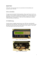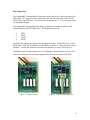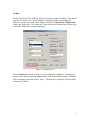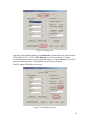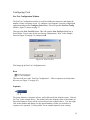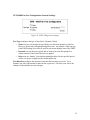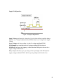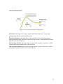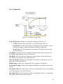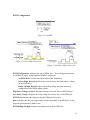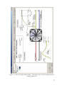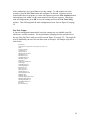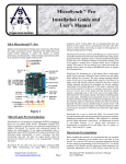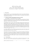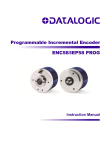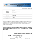
1
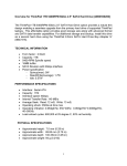
CFM-1000
FAN TEST PLATFORM
User's Manual
Revision 1.0
February 2007
© 2006 Evermore Innovations, LLC
8140 N Mopac Hwy, Building 1, Suite 135, Austin, Texas 78759 USA
Telephone: 512.502.9551
Web Site: www.evermore-innovations.com
E-mail: [email protected]
1
Table of Contents
Table of Contents............................................................................................................ 2
Shipping Box Contents ................................................................................................... 3
Important Safety Instructions .......................................................................................... 4
CFM-1000 Fan Test Platform Users Manual................................................................... 5
About the Platform...................................................................................................... 5
Quick Start.................................................................................................................. 7
Software Installation ............................................................................................... 7
CFM-1000 Hookup................................................................................................. 7
Fan Connection....................................................................................................... 8
Testing.................................................................................................................... 9
Reconfiguration .................................................................................................... 11
Installation of Configuration and Reporting Software................................................ 16
Overview .................................................................................................................. 17
Configuration........................................................................................................ 17
Testing.................................................................................................................. 17
Results .................................................................................................................. 17
Fan Connection......................................................................................................... 18
Configuring Tests ..................................................................................................... 19
Fan Test Configuration Window ........................................................................... 19
Root ...................................................................................................................... 19
Sequence............................................................................................................... 19
CFM-1000 Fan Test Configuration General Settings ............................................. 21
Supply Configuration............................................................................................ 22
Current Measurement............................................................................................ 23
Tach Configuration ............................................................................................... 24
PWM Configuration.............................................................................................. 25
Fan Test Scripts .................................................................................................... 28
Running Tests........................................................................................................... 29
Test Reports.......................................................................................................... 30
Test Data Definitions ............................................................................................ 31
Specifications........................................................................................................ 31
Connector Pinouts..................................................................................................... 32
Connector 1 Pinout ............................................................................................... 32
Connector 2 Pinout ............................................................................................... 32
Product Warranty.......................................................................................................... 33
Customer Service.......................................................................................................... 34
Warranty Service ...................................................................................................... 34
Calibration Service ................................................................................................... 34
Customer Service Contact Information...................................................................... 35
2
Shipping Box Contents
Each CFM-1000 Fan Test Platform includes:
o CFM-1000
o Configurable Termination Block
o CD containing:
§
The Configuration and Reporting Software
§
A USB driver
§
A soft copy of the User’s Manual
o Power Cable
o USB Cable
o Sample fan
o User’s Manual
o Certificate of Calibration
o Warranty Registration Form
3
Important Safety Instructions
The following safety instructions apply to the CFM-1000:
1. Read and follow all warning notices included in this manual.
2. The CFM-1000 should not be operated in environments where the ambient
temperature exceeds 50° C (122° F). Care should also be given to ensure that
adequate air circulation is available for the CFM-1000.
3. The CFM-1000 is designed for indoor use only. Extreme temperature or other
outdoor conditions (rain and moisture) can damage the system.
4. Input AC power to the CFM-1000 must be within 100 Vac to 250 Vac, and 50 Hz
to 60 Hz. Higher voltages will damage the unit.
5. Equipment grounding is vital to ensure safe operation of the CFM-1000. Do not
connect the power cord to an AC receptacle that is not properly grounded.
6. The case should not be opened for any reason. The CFM-1000 contains no
customer serviceable parts. Refer all servicing to Evermore Innovations or an
Authorized Evermore Distributor, Dealer, or Agent.
4
CFM-1000 Fan Test Platform Users Manual
About the Platform
The CFM-1000 is a comprehensive fan test platform designed to characterize the
electrical properties of a fan by running it through a suite of tests and building a datasheet
of the results. Up to four fans can be connected and tested at the same time.
The platform tests the following fan characteristics:
1.
2.
3.
4.
5.
6.
Spinup Time (sec)
Spin Rate (RPM)
Average Current (A)
Maximum Inrush Current (A)
Inrush Duration (ms)
PWM Leakage (•A, static test only)
In testing, the user configures operating parameters and pass/fail criteria. The types of
settings that can be configured on the platform are:
1.
2.
3.
4.
5.
General settings
Supply voltage
Current measurement
Tach
PWM
Configuration settings are described in more detail in the section Configuring Tests.
The platform can be used during product development for fan evaluation, regression
testing, failure analysis, and factory acceptance testing.
Supported fan types include simple two wire fans, fans with tachometers, PWM inputs,
and Fan ID pins.
The platform consists of two major components:
1. PC-based software for configuring the tests and reporting the results
2. The tester box
The configuration and reporting software is a PC-based application which allows the user
to configure specific test sequences for each fan connected to one of the four input
channels of the tester box and then to report the results of each test. It communicates with
the tester box via USB cable.
5
The fans to be tested are plugged into the back of the tester box. A Configurable
Terminal Block is provided to allow easy connection of individual fans and is designed to
fit most extant fans.
6
Quick Start
Follow these quick start instructions to become familiar with the installation and
operation of your CFM-1000.
Software Installation
To begin, insert the included CFM-1000 installation CD into the CD drive of the PC you
would like to use in conjunction with the fan testing platform. The software setup screen
should open. If Autorun is not enabled on your computer, navigate to the CD drive via
Windows Explorer and run setup.exe. Follow the on-screen instructions to install the
CFM-1000 software and USB drivers.
CFM-1000 Hookup
Once the software is installed, connect the power cord, USB cord, and configurable
terminal block to the CFM-1000. Plug the other end of the power cord into an outlet and
the other end of the USB cable into an open USB port on your computer. Power up the
CFM-1000 using the switch on the back of the unit.
Figure 1. CFM-1000 front panel
Figure 2. CFM-1000 back plate
7
Fan Connection
The Configurable Terminal Block is designed to match the pins of a fan to the pins of the
CFM-1000. The vertical rows are connected to the test unit and consist of the TACH,
PWM, PWR, and GND pins. The horizontal rows numbered 1, 2, 3, and 4 connect to the
corresponding fan pins.
The Configurable Terminal Block has been preconfigured to match the pinout of the
included Dynaeon DF129238BA-P fan. The Dynaeon fan pins are:
1.
2.
3.
4.
GND
PWR
TACH
PWM
Verify that the jumpers are placed at the intersections of Row 1 with GND, Row 2 with
PWR, Row 3 with TACH, and Row 4 with PWM (see Figure 3). Then plug in the fan on
Channel 1. On the fan connector, the black wire should be over pin 1 (see Figure 4).
In addition to the four pin connector on the Configurable Terminal Block, there are four
connectors that allow you to connect stripped wires from the fan to the CFM-1000.
Figure 3. Jumper settings
Figure 4. Dynaeon fan plugged in
8
Testing
Double-click on the CFM-1000 Fan Tester icon on your computer’s desktop. This should
open the GUI main screen. On the Channel 1 drop-down menu, select Sample.test.
Make sure that the tester status reads “Ready” and click on Upload Test Configuration.
If the tester status reads “Not Connected”, check to make sure that the unit is powered up
and that the USB cable is connected properly.
Figure 5. Uploading tests
Click on Run Test to run the sequence of tests configured in Sample.test. Alternatively,
the test can be run by pressing the Select button on the CFM-1000 front panel. While the
tests are running, tester status will be “Busy”. When the test is complete, the tester status
will return to “Ready”.
9
Figure 6. Running tests
Once the test has finished running, press Download to download the test report from the
CFM-1000 to the PC. Click on View Reports to view the test results. From the
View/Print Reports screen, you may export the report to a comma-delimited (.csv) file or
print to a connected printer. Exported files are saved to the [Program
Files]\Evermore\CFM1000\res\ directory.
Figure 7. Downloading reports
10
Figure 8. Viewing reports
Reconfiguration
Click on Configure Tests and choose Sample.test from the drop down menu in the Fan
Test Config screen. Double click on Default Test. You will see five tests listed in this
sequence. The first of these is a static test, whereas the other four are dynamic.
Figure 9. Selecting a test to configure
Figure 10. Test sequence in Sample.test
11
1. Select Test 1. This is the static test. Change the PWM Max Leakage value from
3 •A to 10 •A.
2. Now select Test 2. This is a dynamic test run without pulse-width modulation.
Change the Peak Max current from 1.5 A to 2.0 A and change the Max Average
Current from 0.5 A to 0.75 A.
3. Select Test 3. This is a dynamic test run with Driven High, Driven Low PWM.
Change the PWM duty cycle from 50% to 75%.
4. Select Test 4. This is a dynamic test run with Pulled Up High, Driven Low
PWM. Change the PWM pullup resistor strength from 10 k• to 1 k•.
5. Finally, select Test 5. This is a dynamic test run with voltage modulated PWM.
Change the PWM frequency from 1 kHz to 0.7 kHz.
Figure 11. Test 1
12
Figure 12. Test 2
Figure 13. Test 3
13
Figure 14. Test 4
Figure 15. Test 5
14
Click OK to save the configuration changes and return to the GUI main screen. Upload
the test configuration to the CFM-1000 as you did before and run the tests. Download
and view the results report to see the test results.
Now that you are familiar with the basic operation of the CFM-1000, you are ready to
create and configure your own test files for use in fan testing.
15
Installation of Configuration and Reporting Software
The PC based configuration and reporting software must be installed on a system running
Windows 2000 SP4 or Windows XP SP1 or 2.
The software communicates with the tester box via USB, so a USB cable and driver are
provided with the platform in case one is not already present. The enclosed CD contains a
Setup.exe file which will install the application and USB driver.
If you have any installation issues, you may email [email protected].
16
Overview
A fan is characterized by running it through a suite of tests and building a datasheet of the
results. Each test is configured by a set of user-defined parameters that determine how
the test is to be run.
Configuration
Before testing, the user must create a single test or a sequence of tests to be applied to a
fan. This is done through the configuration process. In configuration, the user inputs
specifications on how a test is to be run. These specifications include details about the
PWM drive, tachometer readings, test duration, maximum and minimum values for
pass/fail criteria, etc. A single test file contains one or more “sequences”, each of which
is configured to run a specified number of times and contains one or more “tests”.
Testing
After configuration of a test sequence, the test file can be uploaded to any or all of the
four channels of the CFM-1000. Once the configuration has been uploaded, the test(s)
can be run on fans connected to the appropriate channels. During dynamic tests, average
current, maximum inrush current, and inrush duration are measured and compared
against the pass/fail criteria specified by the user. If tachometer readings are enabled,
spinup time and spin rate are also measured. During static tests, PWM leakage current is
measured and compared against the maximum permissible leakage.
Results
Once testing is complete, the results can be downloaded from the CFM-1000 to the
connected PC and viewed within the CFM-1000 software. Results can also be exported
to a comma-delimited (.csv) file for importation into a spreadsheet software package.
Each result report lists the operating parameters configured by the user, measured
parameters (spinup time, average current, etc.), and whether the fan passed or failed
parameter tests according to the max/min set by the user.
17
Fan Connection
How you connect fans to the CFM-1000 will depends on the fan and your testing needs.
A Configurable Terminal Block is provided for easy connection of fans to the CFM-1000
for testing. Jumpers must be configured according to the pinout of the fan be tested. For
example, a fan with power through pin 1 and ground through pin 2 should have jumpers
at the intersections of row 1 with the PWR column and row 2 with the GND column.
Each row and column should contain only one jumper. Jumpers must be configured for
each channel to be used in testing.
Users can create custom fan harnesses to be used in conjunction with the CFM-1000 for
proprietary fan clusters or other fans for which the Configurable Terminal Block alone is
not appropriate. [put connector specs here]
18
Configuring Tests
Fan Test Configuration Window
The Fan Test Configuration window is used for building test sequences and setting the
number of times a sequence is run. To configure a test sequence, open the configuration
application and press the Configure Tests button. This will open the Fan Test Config
window, Figure 25 shown on page 27.
Then press the New Test File button. This will open the New Fan Test dialog box as
shown below. Type a name for the new fan test configuration (“First” in the example
shown in Figure 16 on page 19), and press OK.
Figure 16. New Fan Test
This brings up the Fan Test Configuration tree.
Root
The root of the tree is the “Fan Test Configuration”. All test sequences are listed under
this root (see Figure 17 on page 20).
Sequence
The arrow indicates a Sequence of tests, and is followed by the Sequence name, “General
QA Test” in the example above. The number below the Sequence name is the number of
times this Sequence of tests will be executed (two in the example above). You may right
click on the number and change it to the desired number of times you wish the test
sequence to be repeated. You may add a Test or another Sequence to an existing
19
Sequence by highlighting the test Sequence and pressing the New Test button for a new
test, or the New Test Sequence button for a new Sequence. In Figure 17 on page 20, for
example, a delay test will run once, followed by Sequence 1 running 5 times, then
Sequence 2 will run three times.
Figure 17. Nested sequences
Double click on Fan Test Configuration then double click on Default Test. Click on
Test 1 to bring up the test configuration screen.
The Fan Test Configuration window consists of five sections: CFM-1000 Fan Test
Configuration General Settings, Supply Configuration, Current Measurement, Tach
Configuration, and PWM Configuration. All desired test conditions will be set in the
fields of these five sections, as explained in the following pages.
20
CFM-1000 Fan Test Configuration General Settings
Figure 18. CFM-1000 general settings
Test Type configures the type of test (Static, Dynamic, Delay).
o Static tests are tests that do not specifically care about the dynamics of the fan.
However, the fan may still spinup during these tests. An example of this test type
is the PWM leakage test, which is used for pin current leakage tests of the PWM.
o Dynamic tests are the most typical and are used to have the fan spinup for a
certain amount of time before the tests are applied.
o Delay tests are “dummy” tests that do nothing but delay for the specified period
of time. No power is applied to the fan during the test.
Test Duration configures the amount of time that the test takes to execute. For a
Dynamic test, this is the amount of time the fan is powered. For Delay tests, this is the
amount of time until the next test is begun.
21
Supply Configuration
Figure 19. Supply configuration
Supply Voltage configures the voltage level, in volts, that the fan is supplied during a
Dynamic test. Voltage modulated fans will PWM from Lower Voltage to the Supply
Voltage.
Lower Voltage is the lower voltage, in volts, for voltage modulated PWM.
PWM Supply box should be checked if voltage modulated PWM is desired.
PWM Freq configures the frequency, in Hertz, that the PWM pin is driven at for a
supply voltage modulated fan.
Duty configures the duty cycle (percentage of time spent high) of the PWM pin for
supply voltage modulated PWM. 100% keeps the pin high and 0% holds it low.
22
Current Measurement
Figure 20. Current measurement configuration
Peak Max is the upper limit, in amps, on the Max Inrush current test. Actual peak
currents larger than this value will Fail the test.
Peak Max Duration is the upper limit, in microseconds, on the Inrush Duration test,
which measures the time spent above the max average current. Actual inrush times larger
than this value will Fail the test.
Max Average Current is the upper limit, in amps, on the Average Current test. Actual
current values larger than this value will Fail the test.
Min Average Current is the lower limit, in amps, on the Average Current test. Actual
current values smaller than this value will Fail the test.
23
Tach Configuration
Figure 21. Tachometer configuration
Tach Configuration configures the tachometer reading type from the fan.
o No Tach should be chosen when there is no tachometer pin on the fan.
o Locked Rotor provides measurement of a simple locked rotor indicator, to know
if the fan has stopped, without measurement of RPMs or spinup time.
o Normal Tach is for full tachometer measurements with pass/fail criteria on spin
rate and spinup time.
Max RPMs is the upper limit on revolutions per minute allowed for the Spin Rate test.
Actual RPMs higher than this value will Fail the test.
Min RPMs is the lower limit on revolutions per minute allowed for the Spin Rate test.
Actual RPMs lower than this value will Fail the test.
Ticks Per Rotation configures the tachometer pin to read one revolution per one or two
rising edges of the tach output pin.
PullupVoltage configures the voltage that the fan’s tach pins are pulled up to.
Tach Pullup Strength configures the strength, in killiohms, of the pullup resistor on the
tach pin.
Max Spinup Time is the upper limit, in seconds, on the Spinup Time test. Actual spinup
times longer than this value will Fail the test.
Min Spinup Time is the lower limit, in seconds, on the Spinup Time test. Actual spinup
times shorter than this value will Fail the test.
24
PWM Configuration
Figure 22. No PWM
Figure 23. Driven High, Driven Low
Figure 24. Pulled Up High, Driven Low
PWM Configuration configures the type of PWM drive. These configuration options
are disabled if supply voltage modulated PWM is configured.
o No PWM Drive runs the fan without pulse width modulation.
o Driven High, Driven Low allows the tester to choose the high and low voltages
for the PWM drive.
o Pulled Up High, Driven Low uses the pullup voltage specified in the tach
configuration with a PWM pullup resistor.
High Drive Voltage configures the upper voltage level on the drive of the PWM pin.
Low Drive Voltage configures the lower voltage level on the drive of the PWM pin.
PWM Freq configures the frequency that the PWM pin is driven at.
Duty configures the duty cycle (percentage of time spent high) of the PWM pin. 100%
keeps the pin high and 0% holds it low.
PWM Pullup Strength configures the pullup resistor on the PWM pin.
25
PWM Max Leakage is the upper limit on the amount of current the PWM input sinks
when driven to 5V. Actual PWM currents larger than this value will Fail the PWM
leakage static test.
26
Figure 25. Fan test configuration window. This display shows the full configuration for
a single sample test.
27
After configuring a test, press Save to save the settings. To add another test to the
sequence, press the New Test button and configure it as desired. Sequences may be
nested within the root sequence; to create sub-sequences press the New Sequence button
and configure tests within it in the same manner as for the root sequence. Once done
with all configurations, press OK to save the settings and close the Fan Test Config
window. This will bring back the main configuration screen, show in Figure 26 on page
29.
Fan Test Scripts
A fan test configuration automatically saves the settings in a user editable script file,
which has a .test file extension. The script filename is displayed in the selection box at
the top of the Fan Test Config screen (First.test in Figure 25 on page 27). This script file
may be modified by the user in a text editor such as Notepad. An example script file is
show below.
[Default.test]
[TestSequence sequencename="General QA Test" repeat="2"]
[Test]
TestType=Dynamic
TestDuration=10
SupplyVoltage=12
PWMType=Driven PWM
PWMfrequency=57
PWMdutyCycle=50
PWMhighVoltage=5.0
PWMlowVoltage=0
NumTachs=1
TachPinType=PWM Tach
TachConfig=1
TachPullupVoltage=5
TachPullupStrength=1
IDpinPresent=No
MinAvgCurrent=1
MaxAvgCurrent=4
MaxInrushCurrent=4
MaxInrushDuration=500
MinRPM=1000
MaxRPM=10000
MaxAllowedSpinupTime=500.0
MinAllowedSpinupTime=0
PWMupperThreshold=2.5
PWMleakageMaxLimit=3
[End Test]
[End TestSequence]
28
Running Tests
From the main screen, each test channel may be configured to use one of the previously
defined test sequences using drop-down menus. After selecting tests for any or all of the
channels, pressing the Upload Test Configuration button will upload the tests to the
CFM-1000, allowing them to be run.
Figure 26. CFM-1000 main screen
Figure 27. CFM-1000 front control panel
After the CFM-1000 has been configured via the PC for a particular test, the test may be
run either by pressing the Run Test button in the GUI (see Figure 26 on page 29) or by
29
pressing the Select button on the front panel of the unit (Figure 27, page 29). While the
test is underway, the display shows a message indicating the test is running. Pressing
Cancel Test in the GUI or the Cancel button on the CFM-1000 will stop any test that is
currently in progress.
Test Reports
Test reports are downloaded from the CFM-1000 via the configuration software.
Pressing the “Download” button downloads the reports from the unit into the PC. After
downloading, the reports may be viewed by pressing the “View Reports” button.
Test Reports may be printed by pressing the Print button on the View / Print Reports
screen. Test Reports may also be saved to a comma delimited (.csv) file, which may be
imported into a spreadsheet software package.
Figure 28 on page 30 shows a sample test report with one test result.
Figure 28. Test results
30
Test Data Definitions
The tests are capable of determining the following characteristics about the fan being
tested:
1. Spinup Time. This is the actual duration of time, in seconds, between the
beginning of the test and time the fan achieved an RPM value within 10 percent
of the final steady state RPM.
2. Spin Rate. This is the rotation rate of the fan, in RPM, as measured at the end of
the test duration.
3. Average Current. The average current value, in amps, sunk by the fan, measured
over a 10ms window at the end of the test duration.
4. Maximum Inrush Current. This is the peak current, in amps, sunk by the fan
during the test.
5. Inrush Duration – The period of time, in milliseconds, during which the fan sunk
more current than the test’s specified Max Average Current.
6. PWM Leakage – The amount of current sunk, in microamperes, by the PWM pin
when the fan is powered up and the PWM pin is pulled high. This is only
measured during a static test.
7. Locked Rotor – Indicates the state of the locked rotor pin, high or low.
Specifications
Test Datum
Average Current
Spinup Time
RPM
Max Inrush Current
Inrush Duration
PWM Leakage Current
Range
0-5.7
0-6553
0-20000
0-5.7
0-500
0-255
Accuracy
+/- 0.1
+/- 0.05
+/- 1
+/- 0.1
+-10
Units
Amps
Seconds
RPM
Amps
Milliseconds
Microamps
31
Connector Pinouts
The CFM-1000 supports up to eight fans with up to six wires per fan. Below are the
connector descriptions and pinouts for each of the 24 pin connectors on the back of the
unit.
Figure 29. Connector pinouts
Connector 1 Pinout
Pin
1
2
3
4
5
6
7
8
9
10
11
12
Function
Fan 1 VCC
Fan 1 Ground
Fan 1 PWM
Fan 1 Tach A
Reserved
Reserved
Fan 2 VCC
Fan 2 Ground
Fan 2 PWM
Fan 2 Tach A
Reserved
Reserved
Pin
13
14
15
16
17
18
19
20
21
22
23
24
Function
Fan 1 VCC
Fan 1 Ground
Fan 1 PWM
Fan 1 Tach A
Reserved
Reserved
Fan 2 VCC
Fan 2 Ground
Fan 2 PWM
Fan 2 Tach A
Reserved
Reserved
Pin
13
14
15
16
17
18
19
20
21
22
23
24
Function
Fan 3 VCC
Fan 3 Ground
Fan 3 PWM
Fan 3 Tach A
Reserved
Reserved
Fan 4 VCC
Fan 4 Ground
Fan 4 PWM
Fan 4 Tach A
Reserved
Reserved
Connector 2 Pinout
Pin
1
2
3
4
5
6
7
8
9
10
11
12
Function
Fan 3 VCC
Fan 3 Ground
Fan 3 PWM
Fan 3 Tach A
Reserved
Reserved
Fan 4 VCC
Fan 4 Ground
Fan 4 PWM
Fan 4 Tach A
Reserved
Reserved
32
Product Warranty
•
•
•
•
•
Evermore Innovations, LLC warrants that the CFM-1000 Fan Test
Platform will be free from defects in material and workmanship under
normal installation for a period of one year from the original date of
purchase.
The obligation of Evermore Innovations under this warranty shall be
limited to repair or replacement (at our option) during the warranty period.
Any part, which proves to be defective in material workmanship under
normal installation, use, or service, is covered under the warranty,
provided the product is returned to an Authorized Evermore Innovations
Distributor, Dealer, or Agent. Note: Transportation or Shipping
Charges are not the responsibility of Evermore Innovations, LLC.
The above warranty shall not apply to defects resulting from misuse,
neglect, accident, destruction, alteration of the serial number, operation
outside of the product environmental specifications, improper electrical
voltages or currents, unauthorized modifications, or repair, alteration, or
maintenance by any person other than Evermore Innovations or an
Authorized Evermore Distributor, Dealer, or Agent.
This warranty is in lieu of all other expressed warranties, obligations, or
liabilities. Evermore Innovations makes no expressed or implied
warranties regarding the quality, merchantability, or fitness for a particular
purpose beyond those that appear in this manual.
In no event will Evermore Innovations be liable for any special, incidental,
consequential or punitive damages for breach of this warranty, expressed
or implied, including, but not limited to, loss of profits or damages to
business or business relations.
33
Customer Service
When contacting the Product Service Department, make sure that you give a full
description of the model and the problem.
Warranty Service
•
•
•
•
•
•
•
The CFM-1000 must be returned to Evermore Innovations or to an
Authorized Evermore Distributor, Dealer, or Agent for warranty service.
A Return Material Authorization (RMA) number must be obtained from
our Product Service Department at [email protected]
before returning the CFM-1000.
Customer shall prepay shipping charges for products returned to Evermore
Innovations for warranty service. Evermore Innovations shall pay
shipping charges for the return of the serviced products to the customer.
However, Evermore Innovations cannot assume liability for duties and
taxes for products returned to customers located outside the USA.
Ship all product returns to:
Evermore Innovations, LLC
Attn: Product Service Department
8140 N Mopac Hwy, Building 1, Suite 135
Austin, Texas 78759 USA
Out-of-Warranty repair rates are available from our Product Service
Department. Repair charges are based on the repair rate at the time of the
return.
Evermore Innovations will either repair or replace (at its option) a
defective product not covered under warranty.
The warranty on a serviced product is 90 days, starting at the date of
service.
Calibration Service
•
•
Evermore Innovations, LLC recommends that the CFM-1000 be calibrated
on a regular interval of one year. Please refer to the Certificate of
Calibration to determine the recommended date of the next calibration.
When the CFM-1000 is due for calibration, please contact Evermore
Innovations or an Authorized Evermore Distributor, Dealer, or Agent.
Calibration charges are available upon request from the Product Service
Department.
34
Customer Service Contact Information
Telephone +1 512.502.9551 (8:30AM to 5:30PM CST Monday - Friday)
Fax
+1 512.346.5675
E-mail
[email protected]
35