1
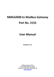
12. Troubleshooting Check the basic items first to judge if the problem was caused by breakdown or misuse. If none of the basic items are related to the problem, please scrutinize the machine according to the ‘Breakdown Diagnosis by Symptoms’ method. 12-1 Basic Breakdown Diagnosis Items 1. The input voltage should be rating voltage ±10% range. The airconditioner may not operate properly if the voltage is out of this range. 2. Is the link cable linking the indoor unit and the outdoor unit linked properly? Check the terminals if the indoor unit and outdoor unit are properly linked by the same number of cables. Otherwise the airconditioner may not operate properly. 3. When a problem occurs due to the contents illustrated in the table below it is a symptom not related to the malfunction of the airconditioner. No Operation of air conditioner Explanation 1 The OPERATION indication LED(GREEN) blinks when a power plug of the indoor unit is plugged in for the first time. It indicates power is on. The LED stops blinking if the operation ON/OFF button on the remote control unit is pushed. 2 In a COOL operation mode, the compressor does not operate at a room temperature higher than the setting temperature that the INDOOR FAN should operate. In a HEAT operation mode, the compressor does not operate at a room temperature lower than the setting temperature that indoor fan should operate. In happens after a delay of 3 minutes when the compressor is reoperated. The same phenomenon occurs when a power is on. As a phenomenon that the compressor is reoperated after a delay of 3 minutes, the indoor fan is adjusted automatically with reference to a temperature of the air blew. 3 Fan speed setting is not allowed in DRY( 4 Compressor stops operation intermittently in DRY( 5 Compressor of the outdoor unit is operating although it is turned off in a HEAT mode. When the unit is turned off while de-ice is activated, the compressor continues operation for up to 9 minutes (maximum) until the deice is completed. 6 Timer LED(GREEN) of the indoor unit lights up and the air conditioner does not operate. Timer is being activated and the unit is in ready mode. The unit operates normally if the timer operation is cancelled. 7 The compressor and indoor fan stop intermittently in HEAT mode. The compressor and indoor fan stop intermittently if room temperature exceeds a setting temperature in order to protect the compressor from overheated air in a HEAT mode. 8 Indoor fan and outdoor fan stop operation intermittently in a HEAT mode. The compressor operates in a reverse cycle to remove exterior ice in a HEAT mode, and indoor fan and outdoor fan do not operate intermittently for within 20% of the total heater operation 9 The compressor stops intermittently in a COOL mode or DRY mode, and fan speed of the indoor unit decreases. The compressor stops intermittently or the fan speed of the indoor unit decreases to prevent inside/outside air frozen depending on the inside/outside air temperature. Samsung Electronics The speed of the indoor fan is set to LL in DRY mode. Fan speed is selected automatically in AUTO mode. ) mode. ) mode. Compressor operation is controlled automatically in DRY mode depending on the room temperature and humidity. 12-1 12-2 Trouble check in the initial status 12-2-1 Diagnosis and marking of the part in trouble. MC24F3A(B)NXAX(XAP)/MC12F3A(B)NXAX(XAP)/MC18F2A(B)NXAX(XAP)/MC12F2NXAX(XAP)/ MC09F3ANXSS/MC06F3ANXSS/MC09F2ANXSS LAMP Description OPERATION TIMER TURBO Indoor unit room temperature sensor error (open or short) Indoor unit heat exchanger temperature sensor error (open or short) Indoor fan motor mal function EEPROM error Option error (option wasn’t set up or option data error) Outdoor error(sensor) Communication error Simultanious operation error(cool, heat) : Lamp on : Lamp off : Lamp flickering MH24F3A(B)NHAC/MH12F3A(B)NHAC/MH12F2A(B)NHAC/MH16F2A(B)NXAX/MH12F2ANXAX LAMP Description OPERATION TIMER TURBO Indoor unit room temperature sensor error (open or short) Indoor unit heat exchanger temperature sensor error (open or short) Indoor fan motor mal function EEPROM error Option error (option wasn’t set up or option data error) Outdoor error(sensor) Communication error Cooling/Heating Confusion Error (MH12F3ANHAC ONLY) : Lamp on 12-2 : Lamp off : Lamp flickering Samsung Electronics Troubleshooting 12-2-2 Operation with abnormal motion No 1 2 Abnormal condition No response from the remote control operation signal. Unable to operate the outdoor unit (MCmodel only) Samsung Electronics Inspection • Plug out and plug in 5 seconds later. • Press the TURBO button with the remote control. • In 3 minutes, check the voltage between the indoor unit terminal block N1 and 1. Initial Diagnosis Able to operate the remote control. OK Unable to operate the remote control. Press the button in the indoor unit. • If it operates, the remote control and indoor unit receiver are in trouble. • If not, the indoor unit is in trouble. AC200V ~ AC240V Problem with the outdoor unit or PCB No power source displayed. Problem with the relay (RY71) or PCB 12-3 12-3 Fault Diagnosis by Symptom 12-3-1 No Power (completely dead)-Initial diagnosis 1. Checklist : 1) Is input voltage normal? 2) Is AC power linked correctly? 3) Is input voltage of DC regulator IC KA7805 of indoor unit PCB normal? (11.8Vdc~12.2Vdc) 4) Is output voltage of DC regulator IC KA780 of indoor unit PCB normal? (4.5Vdc-5.5Vdc) 2. Troubleshooting procedure Unplug the power cord and plug it after 5 seconds Press the Power Button on the remote control unit to operate the air conditioner operate Check the display board does not operate Check the indoor unit control board Yes Check whether 2 wires of power cord are connected correctly to the terminal block and control board. No Reconnect wires correctly Yes Check whether the fuse on the control board is normal. F701 : 3.15(2.5)[A]/250[V] No Replace fuse Yes Check the output of SMPS on the control board. Input power: AC230±15%[V] KA7805 IC Input: DC12[V] KA7805 IC output: DC5[V] No Replace the control board Yes Check the setting temperature 12-4 Samsung Electronics Troubleshooting 12-3-2 When the Indoor Unit Fan Does Not Operate. (Initial Diagnosis) 1. Checklist : 1) Is the indoor unit fan motor properly connected with the connector (CN72)? 2) Is the AC voltage correct? 3) Is HALL IC in indoor fan motor properly connected with the connector (CN44)? 4) Is the running capacitor (CR71) properly connected with PCB board? 2. Troubleshooting procedure After unplugging out the power cord should be reconnected within 5 seconds. Yes No Does the OPERATION lamp blink? Check as in the procedure "No power parts" Yes Does the Solid State Relay(SS71) work properly? Test rod location + - SS71- SS71- No Micom is out of order. Micom should be replaced No PCB is out of order. PCB should be replaced. Normal Voltage 12V Yes Is the supply voltage of the fan motor sufficient? Test rod location PCB CN72 Condition pin #3 and #5 Fan operate Normal Voltage About AC 180V Motor Fan-Capacitor is out of order Yes Fan motor is out of order. Samsung Electronics Replace Motor Fan-Capacitor Fan motor should be replaced. 12-5 Troubleshooting 12-3-3 When the Outdoor Unit Does Not Operate. (Initial Diagnosis) : MC model only 1. Checklist : 1) Is input voltage normal? 2) Is the set temperature of the remote control higher than room temperature in COOL mode? 3) Is the POWER IN wire-power(N) linked correctly? 4) Is the outdoor unit properly connected with the TERMINAL BLOCK connecto? 2. Troubleshooting procedure After unplugging out the power cord should be reconnected within 5 seconds. No Check as in the procedure "No Power parts" Does the OPERATION lamp blink Yes Does the timer lamp blink during operation? No Room temperature sensor is out of order Yes ① ② ③ No Is the power relay RY71 operated by adjusting the room temperature? Test rod location + - Condition IC04 Pin No.38 GND RY71 ON PCB should be checked. Micom is out of order. Normal Voltage PCB should be checked. DC4.8V Yes Is rating voltage ±10% range applied relay between Terminal block No. N(1) and No. 1 No Power relay is out of order Power relay should be replaced. Yes Outdoor unit is out of order. ① No Yes ② Is the room sensor normal register? 10°C 20°C 30°C 17.96kΩ 12.09kΩ 8.3kΩ ③ 12-6 Samsung Electronics Troubleshooting 12-3-4 When the UP/DOWN Louver Motor Does Not Operate. (Initial Diagnosis) 1. Checklist : 1) Is input voltage normal? 2) Is the UP/DOWN louver motor properly connected with the connector (CN61)? 2. Troubleshooting procedure Remove power cord and plug in again in approx. 5 seconds. Does the OPERATION lamp blink? No Check as in the procedure "No Power parts". Yes Does operation start when swing button of the remote control unit pushed? Yes Normal No Voltage at pin #57~#60 of micom (IC04) change? (Squarewave) No Micom (IC04) is faulty. Yes Voltage at pin #14~#16 of IC06(ULN2003A) and pin #15 of IC05 change? (Squarewave) No Driver IC05/IC06 (ULN2003A) is faulty. Yes UP/DOWN louver motor is faulty. Samsung Electronics 12-7 Troubleshooting 12-3-5 In the HEAT mode, When there is no warm air current. Check this first : MH model only 1) Is the set temperature of Remote Control lower than room temperature in Heat mode? 2) Is the Outdoor PCB properly conneted with 4 way V/V connector? Is the Thermo off? Yes Change the setting temperature of remote control. Yes Operate it with a heating mode as soon as the defrosting is finished. Yes After 3 minutes, cooling and heating start automatically. No Is the unit in the defrosting operation? No Is the compressor in 3 minutes off? No No Indoor operation SW is on. Turn the SW On. Yes Is much frost in the heat exchanger? Yes Is the outdoor air sensor and outdoor heat exchanger attached correctly? No Yes Attach the sensor correctly. Over shortage of the refrigerant No Does the 4 way valve operate normally? No Is the 4 way valve connector connected correctly? No Connect the connecter correctly. Yes Check the resistance value of 4 way valve coil. NG 4-WAY valve coil error OK Dose the voltage of AC 220V apply to the connector of 4 way valve coil during the operation? No Exchange the outdoor PCB. Yes Go to the next page 12-8 4 way valve main body error Samsung Electronics Troubleshooting In the HEAT mode, When there is no warm air current. Check this first : MH model only (cont.) From the previous page Does the EEV operate normally? No No Is much frost in the heat exchanger? Connect the connector. Yes Check the resistance value of EEV coil. NG EEV coil error OK Yes Is much frost in the heat exchanger? No Exchange the out PCB. Yes EEV main body error Does the outdoor fan operate at the operation of compressor? Yes The over shortage of refrigerant, Insufficient Capacity, Load estimation error No Is the outdoor fan connected correctly? No Connect the connector. Yes Check the resistance value of outdoor fan. NG Outdoor fan error OK Dose the voltage of DC300V apply to the connector of outdoor fan during the operation of outdoor unit? Yes Check the motor wire. No Outdoor PCB error Samsung Electronics 12-9 Troubleshooting 12-3-6 Room temperature sensor failure LAMP Description OPERATION TIMER TURBO Indoor unit room temperature sensor error (open or short) : Lamp off : Lamp flickering Detach the assembly sensor from the ASS'Y main PCB CN43 connector and measure the sensor resistance with an ohmmeter (tester). Is the sensor resistance value 10KΩ±3% at the room temperature of 25˚C? No ASS'Y Sensor Replace SENSOR Resistance Value : 20˚C-12.09kΩ 30˚C-8.31kΩ 35˚C-6.94kΩ 40˚C-5.83kΩ Yes Connect the sensor to CN43, supply power, and measure the voltage of #1 and #2 of the CN43 connector. Below 0.5V? Yes Poor ASS'Y PCB Replace No Over 4.9V? Yes Poor ASS'Y PCB Replace No MICOM Error or Connector(CN43) check 12-10 Samsung Electronics Troubleshooting 12-3-7 Room Pipe sensor failure LAMP OPERATION Description TIMER TURBO Indoor unit heat exchanger temperature sensor error (open or short) : Lamp off : Lamp flickering 1. Check the assembly condition of the sensor connector(CN43) on the indoor unit Main PCB and if not assembled, reassemble the connector accurately. 2. Detach the room pipe sensor connector(CN43) and check the resistance between Pin #3 and #4. Temperature(˚C) Resistance Value(Kohm) Temperature(˚C) Resistance Value(Kohm) 15 14.68 30 8.31 20 12.09 35 6.94 25 10 40 5.83 Others The data tolerance is ±3%. If the above data is not met, replace the room pipe sensor. 3. Assemble the room pipe sensor to PCB, plug in, and check the voltage of connector 3 and 4. If the resistance is below 0.5V or over 4.9V, replace the indoor Main PCB. (short or disconnected in the PCB board) Samsung Electronics 12-11 Troubleshooting 12-3-8 When the remote control is not receiving. 1. Check the connector was normally assembled. 2. Put the set in operation and check the valtage of Vout(+) and Gnd(-) of thr RM01 while operating the remote control. When the voltage descends below 3V, the assembly module PCB is ormal and the main PCB is poor. Then replace the main PCB. 12-12 Samsung Electronics 12-4 PCB Inspection Method 12-4-1 Pre-inspection Notices 1. Check if you pulled out the AC power plug when you eliminate the PCB or front panel. 2. Don’t hold the PCB side not impose excessive force on it to eliminate the PCB. 3. Don’t pull the lead wire but hold the whole housing to connect or disconnect a connector to the PCB. 12-4-2 Inspection Procedure 1. Check connector connection and peeling of PCB or bronze coating pattern when you think the PCB is broken. 2. PCB composition H/P Indoor mode[MH24F3A(B)NHAC/MH12F3A(B)NHAC/MH12F2A(B)NHAC/MH16F2A(B)NXAX/MH12F2ANXAX] • Main PCB Part : MICOM And Surrounding Circuit, Room Fan Motor Driving Circuit and Control Circuit, Sensor Driving Circuit, Power Circuit Of DC12V Aand DC5V, and Buzzer Driving Circuit, Blade Driving Circuit. • Sub PCB Part : AC communication circuit • Display PCB Part : LED Lamp Display, Room Adderss Setting Circuit, Remocon Module, Switch C/O Indoor model(MC24F3A(B)NXAX(XAP)/MC12F3A(B)NXAX(XAP)/MC18F2A(B)NXAX(XAP)/MC12F2NXAX(XAP)/ MC09F3A(B)NXSS/MC06F3A(B)NXSS/MC09F2A(B)NXSS] • POWER PCB Part : Relay, Room Fan Motor Driving Circuit And Control Circuit, Power Circuit Of Dc12v And DC5V, and Buzzer Driving Circuit • Main PCB Part : MICOM and Surrounding Circuit, LED Lamp, Sensor Driving Circuit, Switch H/P Outdoor model [MH48F3A(B)XHAC / MH24F2A(B)XHAC / MH32F2A(B)XXAX / MH24F2AXXAX] • Main PCB Part : MICOM And Surrounding Circuit, Outdoor AC Load (Compressor, Fan Motor, Bypass Valve, 4 way Valve) Driving Circuit, Eev Driving Part, Power Circuit Of DC 12V And DC 5V, Sensor Driving Circuit, Data Display Circuit, Ac Communication Circuit C/O Outdoor model [MC48F3A(B)XXAX(XAP) / MC20F3A(B)XXSS] • Main PCB Part : MICOM and Surrounding Circuit, Outdoor AC load (Compressor, Fan Motor, Bypass Valve, Solenoid Valve) Driving Circuit, Power Circuit of DC12V and DC 5V, Sensor Driving Circuit, Indoor Comp Singal Receive Circuit Samsung Electronics 12-13 Troubleshooting 12-4-3 Detailed Inspection Procedure H/P Indoor model [MH24F3A(B)NHAC / MH12F3A(B)NHAC / MH12F2A(B)NHAC / MH16F2A(B)NXAX / MH12F2ANXAX] No Procedure Inspection Method Cause 1 Plug out and pull the PCB out of the electronic box. Check the PCB fuse. 1) Is the fuse disconnected? - Over current - Indoor fan motor short - AC part pattern short of the main PCB 2 Supply power. If the operation lamp twinkles at this time, 1) ~ 4) no relation. 1) Is the BD71 input voltage AC200V ~ AC240V? - Power Cord is fault, Fuse Open, Wrong Power - Cable Wiring, AC Part is faulty - Choke Coil (FT71) is fault 2) Is the voltage between both terminals of the C101about DC 310V? - Bridge Diode (BD71) is faulty 3) Is the voltage between both terminals of the C103 on the second side of the switching transformer (ST11) about DC 12V? - Switching Transformer or Power circuit is faulty 4) Is the voltage between both terminals of OUT and GND of IC04(KA78L05) about DC 5V? - Regulator IC (IC02) or Power circuit is faulty 1) Is the voltage over AC180V being imposed on the terminal #3 and #5 of the fan motor connector(CN72) - SSR(SS71) is faulty - Micom is out of order - Communication between indoor and outdoor is faulty 3 Press the ON/OFF button 1. Fan mode on C/O Indoor model [MC24F3A(B)NXAX(XAP)/MC12F3A(B)NXAX(XAP)/MC18F2A(B)NXAX(XAP)/MC12F2NXAX(XAP) MC09F3A(B)NXSS/MC06F3A(B)NXSS/MC09F2A(B)NXSS] No Procedure Inspection Method Cause 1 Plug out and pull the PCB out of the electronic box. Check the PCB fuse. 1) Is the fuse disconnected? - Over current - Indoor fan motor short - AC part pattern short of the main PCB 2 Supply power. If the operation lamp twinkles at this time, 1) ~ 4) no relation. 1) Is the BD71 input voltage AC200V ~ AC240V? - Power Cord is fault, Fuse Open, Wrong Power - Cable Wiring, AC Part is faulty - Choke Coil (FT71) is fault 2) Is the voltage between both terminals of the C101 about DC 310V? - Bridge Diode (BD71) is faulty 3) Is the voltage between both terminals of the C103 on the second side of the switching transformer (ST11) about DC 12V? - Switching Transformer or Power circuit is faulty 4) Is the voltage between both terminals of OUT and GND of IC04(KA78L05) about DC 5V? - Regulator IC (IC02) or Power circuit is faulty 1) Is the voltage over AC180V being imposed on the terminal #3 and #5 of the fan motor connector(CN72) - SSR(SS71) is faulty - Micom is out of order 2) Check the voltage of both terminals of indoor terminal block N and C after 3 minutes operation : AC 220V - RY71 is faulty - Connection is faulty 3 12-14 Press the ON/OFF button 1. Cooling mode on (setting temp. must be higher than indoor temp.) Samsung Electronics Troubleshooting Detailed Inspection Procedure(cont.) H/P Outdoor model [MH48F3A(B)XHAC / MH24F2A(B)XHAC / MH32F2A(B)XXAX / MH24F2AXXAX] No Procedure Inspection Method Cause 1 Plug out and pull the PCB out of the electronic box. Check the PCB fuse. 1) Is the fuse disconnected? - Over current - Indoor fan motor short - AC part pattern short of the main PCB 2 Supply power. If the 7-segment display at this time, 1) ~ 4) no relation. 1) Is the voltage between both terminals #1 and #3 of the transformer input connector(GT-2) voltage AC200V ~ AC240V? - Over current - Indoor fan motor short - AC part pattern short of the main PCB 1) Is the voltage between both terminals #1 and #3 of the transformer input connector(GT-2) voltage AC200V ~ AC240V? - Transformer is faulty 3) Is the voltage between 12V line and ground line that marked on the PCB about 12V? - Fuse Open - Regulator IC KA7812(IC01) or Power circuit is faulty 4) Is the voltage between 5V line and ground line that marked on the PCB about 5V? - Regulator IC KA7805(IC02) or Power circuit is faulty C/O Outdoor model [MC48F3A(B)XXAX(XAP) / MC20F3A(B)XXSS] No Procedure Inspection Method Cause 1 Plug out and pull the PCB out of the electronic box. Check the PCB fuse. 1) Is the fuse disconnected? - Over current - Indoor fan motor short - AC part pattern short of the main PCB 2 Supply power. If the 7-segment display at this time, 1) ~ 4) no relation. 1) Is the voltage between both terminals #1 and #3 of the transformer input connector(GT-2) voltage AC200V ~ AC240V? - Power Cord is fault, Fuse Open, Wrong Power - Cable Wiring, AC Part is faulty 2) Is the voltage between both terminals #1 and #3 of the transformer output connector(CN11) voltage AC17V ~ AC19V? - Transformer is faulty 3) Is the voltage between 12V line and ground line that marked on the PCB about 12V? - Fuse Open - Regulator IC KA7812(IC01) or Power circuit is faulty 4) Is the voltage between 5V line and ground line that marked on the PCB about 5V? - Regulator IC KA7805(IC02) or Power circuit is faulty Samsung Electronics 12-15 12-4-4 Temperature Sensor Feature Conversion Table(Room Temperature Sensor); 103AT Temperature Sensor Resistance Temperature Sensor Resistance Temperature Sensor Resistance Temperature Sensor Resistance [˚C] [Kohm] [˚C] [Kohm] [˚C] [Kohm] [˚C] [Kohm] 70 69 68 67 66 65 64 63 62 61 60 2.229 2.296 2.365 2.437 2.512 2.589 2.669 2.752 2.838 2.928 3.021 49 48 47 46 45 44 43 42 41 40 4.300 4.444 4.594 4.749 4.912 5.080 5.256 5.439 5.630 5.828 29 28 27 26 25 24 23 22 21 20 8.622 8.944 9.281 9.632 10 10.380 10.780 11.200 11.630 12.090 9 8 7 6 5 4 3 2 1 0 18.700 19.480 20.290 21.150 22.050 22.990 23.900 25.030 26.130 27.280 59 58 57 56 55 54 53 52 51 50 3.116 3.216 3.319 3.426 3.537 3.652 3.772 3.897 4.026 4.161 39 38 37 36 35 34 33 32 31 30 6.033 6.246 6.468 6.699 6.941 7.192 7.455 7.729 8.015 8.313 19 18 17 16 15 14 13 12 11 10 12.560 13.060 13.570 14.120 14.680 15.280 15.900 16.550 17.240 17.960 -1 -2 -3 -4 -5 -6 -7 -8 -9 28.470 29.720 31.040 32.430 33.890 35.430 37.050 38.760 40.560 Temperature Sensor Characteristic Curve Temperature (˚C) 70 60 50 40 30 At the temperature of 25˚C(10KΩ) 20 10 0 -10 -9 5 10 15 20 25 30 35 40 Resistance Value (Kohm) 12-16 Samsung Electronics 12-5 Main Part Inspection Method Part Room Temperature Sensor Room Fan Motor Breakdown Inspection Method Measure resistance with a tester Normal At the normal temperature 37kΩ~ 8.3kΩ(-7˚C~+30˚C) *Refer to Table 12-4-4. Abnormal ∞, 0Ω . . . Open or Short Measure the resistance between terminals of the connector (CN72) with a tester. Abnormal Outdoor Fan Motor Measure resistance with a tester Abnormal Stepping Motor Samsung Electronics ∞, 0Ω . . . Open or Short ∞, 0Ω . . . Open or Short Measure the resistance between the red wire and each terminal wire with a tester. Normal About 300Ω at the normal temperature (20˚C ~ 30˚C) Abnormal ∞, 0Ω . . . Open or Short 12-17