1
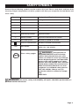
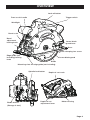
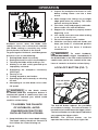
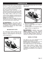
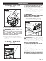
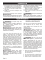
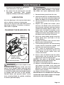
20 Volt Circular Saw
241-0428
OPERATOR’S MANUAL
CAUTION: To Reduce The Risk Of Injury, User Must Read And
Understand The Operator’s Manual. Save These Instructions For
Future Reference.
For questions / comments, technical assistance or repair parts –
Please Call Toll Free: 1-866-917-4374. (M-F 8am – 6pm EST.)
table of contents
Safety Symbols. . . . . . . . . . . . . . . . . . . . . . . . . . . . . . . . . . . . . . . . . . . . . . . . . . . . . . . . . . Page 2
Safety Instructions. . . . . . . . . . . . . . . . . . . . . . . . . . . . . . . . . . . . . . . . . . . . . . . . . . . . . . . Page 3
Overview/ Specifications. . . . . . . . . . . . . . . . . . . . . . . . . . . . . . . . . . . . . . . . . . . . . . . . . . Page 8
Assembly . . . . . . . . . . . . . . . . . . . . . . . . . . . . . . . . . . . . . . . . . . . . . . . . . . . . . . . . . . . . . Page 10
Operation . . . . . . . . . . . . . . . . . . . . . . . . . . . . . . . . . . . . . . . . . . . . . . . . . . . . . . . . . . . . . Page 11
Maintenance. . . . . . . . . . . . . . . . . . . . . . . . . . . . . . . . . . . . . . . . . . . . . . . . . . . . . . . . . . . Page 19
Troubleshooting. . . . . . . . . . . . . . . . . . . . . . . . . . . . . . . . . . . . . . . . . . . . . . . . . . . . . . . . Page 21
Warranty. . . . . . . . . . . . . . . . . . . . . . . . . . . . . . . . . . . . . . . . . . . . . . . . . . . . . . . . . . . . . . Page 22
safety symbols
Some of these following symbols may be used on this tool. Please study them and learn their
meaning. Proper interpretation of these symbols will allow you to operate the tool better and
more safely.
Symbol
Name
Designation / Explanation
V
Volts
Voltage
A
Amperes
Current
Hz
Hertz
Frequency (cycles per second)
W
Watts
Power
Minutes
Time
∿
Alternating current
Type of current
�
Direct current
Type of characteristic of current
no
No-load speed
Rotational speed at no load
Class II construction
Double insulated construction
Per minute
Revolutions, strokes, surface speed
orbits, etc., per minute
Min
.../min
Wear safety goggles
WARNING: The operation of
any power tool can result in foreign
objects being thrown into your eyes,
which can result in severe eye damage.
Before beginning power tool operation,
always wear safety goggles or safety
glasses with side shields and a full-face
shield when needed. We recommend a
Wide Vision Safety Mask for use over
eyeglasses or standard safety glasses
with side shields. Always use eye
protection which is marked to comply
with
ANSI Z87.1.
WARNING: To ensure safety and reliability, all repairs should be performed by a
qualified service technician.
Page 2
safety INSTRUCTIONS
The purpose of safety symbols is to attract your attention to possible dangers. The safety
symbols and the explanations with them deserve your careful attention and understanding.
The symbol warnings do not, by themselves, eliminate any danger. The instructions and
warnings they give are no substitutes for proper accident prevention measures.
WARNING: Be sure to read and understand all safety instructions in this manual,
including all safety alert symbols such as “DANGER,” ”WARNING,” and “CAUTION”
before using this tool. Failure to following all instructions listed below may result in
electric shock, fire, and/or serious personal injury.
SYMBOL MEANING
AFETY ALERT SYMBOL: Indicates DANGER, WARNING,
S
May be used in conjunction with other symbols or pictographs.
OR
CAUTION.
DANGER: Indicates an imminently hazardous situation, which, if not avoided,
will result in death or serious injury.
WARNING: Indicates a potentially hazardous situation, which, if not avoided, could
result in death or serious injury.
CAUTION: Indicates a potentially hazardous situation, which, if not avoided, could
result in minor or moderate injury.
NOTICE: (Without Safety Alert Symbol) Indicates a situation that may result in
property damage.
SAVE THESE INSTRUCTIONS!
Page 3
Page 3
safety INSTRUCTIONS
WARNING:
Read all safety
warnings and instructions.Failure to
follow the warnings and instructions
may result in electric shock, fire and / or
serious injury.
Save all warnings and instructions for
future reference.
The term power tool in the warnings
refers to your mains-operated (corded)
power
tool
or
battery-operated
(cordless) power tool.
WARNING: Risk of fire and
electric shock. Dry location use only.
Do not expose to rain. Risk of injury.
Work area safety
1. Keep work area clean and well lit.
Cluttered or dark areas invite accidents.
2. Do not operate power tools in
explosive atmospheres, such as in the
presence of flammable liquids, gases
or dust. Power tools create sparks
which may ignite the dust or fumes.
3. Keep children and bystanders away
while operating a power tool. Distractions
can cause you to lose control.
Electrical safety
1. Power tool plugs must match the
outlet. Never modify the plug in any
way. Do not use any adapter plugs
with earthed (grounded) power tools.
Unmodified plugs and matching outlets
will reduce risk of electric shock.
2. Avoid body contact with earthed
or grounded surfaces such as pipes,
radiators, ranges and refrigerators.
There is an increased risk of electric shock
if your body is earthed or grounded.
3. Do not expose power tools to
rain or wet conditions. Water entering
a power tool will increase the risk of
electric shock.
4. Do not abuse the cord. Never
use the cord for carrying, pulling or
unplugging the power tool. Keep the
cord away from heat, oil, sharp edges
or moving parts. Damaged or entangled
cords increase the risk of electric shock.
5. When operating a power tool
outdoors, use an extension cord
suitable for outdoor use. Use of a cord
suitable for outdoor use reduces the risk
of electric shock.
6. If operating a power tool in a
damp location is unavoidable, use a
ground fault circuit interrupter (GFCI)
protected supply. Use of a GFCI
reduces the risk of electric shock.
Personal safety
1. Stay alert, watch what you are
doing and use common sense when
operating a power tool. Do not use the
tool while tired or under the influence
of drugs, alcohol, or medication. A
moment of inattention while operating
power tools may result in serious
personal injury.
2.Use personal protective equipment.
Always wear eye protection. Protective
equipment such as a dust mask, nonskid safety shoes, hard hat, or hearing
protection,
used
for
appropriate
conditions, will reduce personal injuries.
3. Prevent unintentional starting.
Ensure that the switch is in the offposition before connecting to power
source and / or battery pack, picking
up or carrying the tool. Carrying power
tools with your finger on the switch or
energizing power tools that have the
switch on invites accidents.
Page 4
safety INSTRUCTIONS
4. Remove any adjusting key or wrench
before turning the power tool on. A wrench
or a key left attached to a rotating part of the
power tool may result in personal injury.
5. Do not overreach. Keep proper footing
and balance at all times. This enables
better control of the power tool in
unexpected situations.
6. Dress properly. Do not wear loose
clothing or jewelry. Keep your hair, clothing
and gloves away from moving parts. Loose
clothes, jewelry or long hair can be caught in
moving parts.
7. If devices are provided for the
connection of dust extraction and
collection facilities, ensure that these are
connected and properly used. Use of these
devices can reduce dust-related hazards.
5. Maintain power tools. Check for
misalignment or binding of moving parts,
breakage of parts and any other condition
that may affect the power tool’s operation.
If damaged, have the power tool repaired
before use. Many accidents are caused by
poorly maintained power tools.
6. Keep cutting tools sharp and clean.
Properly maintained cutting tools with sharp
cutting edges are less likely to bind and are
easier to control.
7. Use the power tool, accessories,
tool bits etc., in accordance with these
instructions, taking into account the
working conditions and the work to be
performed. Use of the power tool for
operations different from those intended
could result in a hazardous situation.
USE AND CARE of the
power tools
BATTERY TOOL USE
AND CARE
1. Do not force the power tool. Use the
correct power tool for your application. The
correct power tool will do the job better
and more safely at the rate for which it was
designed.
2. Do not use the power tool if the switch
does not turn it on and off. Any power tool
that cannot be controlled with the switch is
dangerous and must be repaired.
3. Disconnect the plug from the power
source and/or the battery pack from the
power tool before making any adjustments,
changing accessories, or storing power
tools. Such preventive safety measures
reduce the risk of starting the power tool
accidentally.
4. Store idle power tools out of the reach
of children and do not allow persons
unfamiliar with the power tool or these
instructions to operate the power tool.
Power tools are dangerous in the hands of
untrained users.
1. Recharge only with the charger
specified by the manufacturer. A charger
that is suitable for one type of battery pack
may create a risk of fire when used with
another battery pack.
2. Use power tools only with specifically
designated battery packs. Use of any other
battery packs may create a risk of injury and fire.
3. When the battery pack is not in use,
keep it away from other metal objects,
such as paper clips, coins, keys, nails,
screws or other small metal objects that
can make a connection from one terminal
to another. Shorting the battery terminals
together may cause burns or a fire.
4. Under abusive conditions, liquid may
be ejected from the battery; avoid contact.
If contact accidentally occurs, flush with
water. If liquid contacts eyes, also seek
medical help. Liquid ejected from the battery
may cause irritation or burns.
Page 5
safety INSTRUCTIONS
Service
1. Have your power tool serviced by
a qualified repair person using only
identical replacement parts. This will
ensure that the safety of the power tool
is maintained.
SPECIFIC SAFETY RULES FOR
CIRCULAR SAWS
1. Danger
a) Keep hands away from cutting area
and blade. Keep your second hand
on auxiliary handle, or motor housing.
If both hands are holding the saw, they
cannot be cut by the blade.
b) Do not reach underneath the work
piece. The guard cannot protect you
from the blade below the work piece.
c) Adjust the cutting depth to the
thickness of the work piece.. Less than
a full tooth of the blade teeth should be
visible below the work piece.
d) Never hold piece being cut in your
hands or across your leg. Secure the
work piece to a stable platform. It is
important to support the work properly
to minimize body exposure, blade
binding, or loss of control.
e) Hold power tool by insulated gripping
surfaces when performing an operation
where the cutting tool may contact
hidden wiring or its own cord. Contact
with a ‘live’ wire will also make exposed
metal parts of the power tool ‘live’ and
shock the operator.
f) When ripping always use a rip fence or
straight edge guide. This improves the
accuracy of cut and reduces the chance
of blade binding.
g) Always use blades with correct size
and shape (diamond versus round) of
arbor holes. Blades that do not match
the mounting hardware of the saw will
run eccentrically, causing loss of control.
h) N
ever use damaged or incorrect blade
washers or bolt. The blade washers and bolt
were specially designed for your saw, for
optimum performance and safety of operation.
2. Causes and operator prevention
of kickback
a) kickback is sudden reaction to a pinched,
bound or misaligned saw blade, causing
an uncontrolled saw to lift up and out of
the workpiece toward the operator;
b) when the blade is pinched or bound
tightly by the kerf closing down, the
blade stalls and the motor reaction
drives the unit rapidly back toward
the operator;
c) if the blade becomes twisted or
misaligned in the cut, the teeth at the
back edge of the blade can dig into
the top surface if the wood causing the
blade to climb out the kerf and jump
back toward the operator.
3. Kickback is the result of saw misuse
and/or incorrect operation procedures or
conditions and can be avoided by taking
proper precautions as given below.
a) Maintain a firm grip with both hands on
the saw and position your arms to resist
kickback forces. Position your body to
either side of the blade, but not in line
with the blade. Kickback could cause the
saw to jump backwards, but kickback
forces can be controlled by the operator,
if proper precautions are taken.
b) When blade is binding, or when
interrupting a cut for any reason, release
the trigger and hold the saw motionless
in the material until the blade comes to a
complete stop. Never attempt to remove
the saw from the work or pull the saw
backward while the blade is in motion or
kickback may occur. Investigate and take
corrective actions to eliminate the cause of
blade binding.
c) When restarting a saw in the work piece,
centre the saw blade in the kerfs and
check that saw teeth are not engaged
into the material. If saw blade is binding,
It may walk up or kickback from the work
piece as the saw is restarted.
Page 6
safety INSTRUCTIONS
d) S
upport large panels to minimize the
risk of blade pinching and kickback.
Large panels tend to sag under their own
weight. Supports must be placed under
the panel on both sides, near the line of
cut and near the edge of the panel.
e) Do not use dull or damaged blades.
Unsharpened or improperly set blades
produce narrow kerfs causing excessive
friction, blade binding and kickback.
f) Blade depth and bevel adjusting locking
levers must be tight and secure before
making cut. If blade adjustment shifts
while cutting, it may cause binding
and kickback.
g) Use extra caution when making a
‘plunge cut’ into existing walls or other
blind areas. The protruding blade may
cut objects that can cause kickback.
4. Safety instructions for saws with inner
pendulum guard
a) Check lower guard for proper closing
before each use. Do not operate the
saw if lower guard does not move
freely and close instantly. Never clamp
or tie the lower guard into the open
position. If saw is accidentally dropped,
lower guard may be bent. Raise the
lower guard with the retracting handle
and make sure it moves freely and does
not touch the blade or any other part, in
all angles and depths of cut.
b) Check the operation of the lower guard
spring. If the guard and the spring are
not operating properly, they must be
serviced before use. Lower guard may
operate sluggishly due to damaged parts,
gummy deposits, or a build-up of debris.
c) Lower guard should be retracted
manually only for special cuts such
as’ plunge cuts’ and ‘compound
cuts’ .Raise lower guard by retracting
handle and as soon as blade enters
the material, the lower guard must be
released. For all other sawing, the lower
guard should operate automatically.
Page 7
Always observe that the lower guard is
covering the blade before placing saw
down on bench or floor. An unprotected,
coasting blade will cause the saw to walk
backwards, cutting whatever is in its path.
Be ware of the time it takes for the blade to
stop after switch is released.
5. Use only with battery and charger
listed below.
Battery pack
Charger
252-8024
252-8029
252-8030
252-8031
252-8032
252-8033
252-8034
252-8036
252-8037
252-8044
OVERVIEW
Lock-off button
Front assist handle
Trigger switch
Worklight
Bevel scale
Bevel
adjustment
locking knob
Lower blade
guard lever
Base
Blade clamping hex screw
Edge guide (not
including) locking
knob
Lower blade guard
Blade
Mounting slots for edge guide (not including)
Spindle lock button
Blade wrench
(Storage in tool)
Depth-of-cut scale
Depth-of-cut
adjustment lever
Motor housing
Page 8
SPECIFICATIONS
PRODUCT SPECIFICATIONS
No load Speed
4500RPM
Blade Diameter
6-1/2-in. (165mm)
Blade Arbor
5/8 in. (16mm)
Cutting Depth at 90°
2-1/8-in.
Cutting Depth at 45°
1-3/4-in.
Maximum Bevel Angle
Adjustable 0-50°
Tool weight (without battery)
5lbs. 10oz.
ASSEMBLY
PLASTIC UPPER AND
LOWER BLADE GUARD WITH
ANTI-SNAG FEATURE
Lightweight blade guards provide protection
from the blade. The self-retracting lower
blade guard features an anti-snag design for
more efficient cutting.
ELECTRIC BRAKE
The saw has an electric brake to quickly
stop the blade from rotating.
LED WORKLIGHT
The fixed-position LED worklight, located
on the front of the saw, allows better
cut-line visibility.
INTEGRATED RIP AND
CROSSCUT RULER
The base has integrated rip and crosscut
rulers for quick reference when making
repetitive cuts.
HEX KEY STORAGE
0° TO 50° BEVEL ADJUSTMENT
The bevel adjustment knob allows you to set
the circular saw for bevel cuts from 0° to 50°.
Page 9
The blade screw hex key is conveniently
stored on board, at the front of the
motor housing.
ASSEMBLY
ERGONOMIC DESIGN
The design of the saw allows proper two hand
control when cutting. It has been designed to
be comfortable and easy to grasp.
SPINDLE LOCK BUTTON
The spindle lock button allows you to secure
the blade when turning the blade screw.
WARNING: Do not attempt to modify
this circular saw or create accessories not
recommended for use with this saw. Any
such alteration or modification is misuse
and could result in a hazardous condition
leading to possible serious injury.
WARNING: To prevent accidental
starting that could cause serious personal
injury, always remove the battery pack
from the circular when assembling parts.
LOCK-OFF BUTTON
UNPACKING
The lock-off button reduces the possibility of
accidental starting. The button can be used
on either the left or right of the trigger switch.
This
product
has
been
shipped
completely assembled.
1. Carefully remove the tool and any
accessories from the box. Make sure that all
items listed in the packing list are included.
2. Inspect the tool carefully to make
sure no breakage or damage occurred
during shipping.
3. Do not discard the packing material
until you have carefully inspected and
satisfactorily operated the tool.
DEPTH ADJUSTMENT LEVER
The depth adjustment lever adjusts the
cutting capacity of 0 to 2-1/8-in. at 90° and 0
to 1-3/4-in. at 45°.
WARNING: If any part is broken or
missing, do not attempt to plug in the power
cord or operate the tool until the broken or
missing part is replaced. Failure to do so
could result in possible serious injury.
CONTENTS
6-1/2-in.Circular saw, Hex wrench and
Operator’s manual
Page 10
OPERATION
TO ATTACH BATTERY
PACK (Fig. 1)
FIG. 1
the battery pack can cause damage to
internal components.
BLADE GUARD SYSTEM (Fig. 2)
FIG. 2
Lower blade guard is in up
position when making a cut
Blade exposed on
underside of workpiece
NOTICE: Use with the battery pack listed
on page 8 only.
1. Make sure that the circular saw is “OFF”
2. Align the raised rib on the battery pack
with the grooves on the bottom of the
saw, and then attach the battery pack to
the saw.
NOTICE: Make sure that the latch on the
battery pack snaps into place and the
battery pack is secured to the tool before
beginning operation.
TO DETACH BATTERY
PACK (Fig. 1)
1. L
ock the trigger switch on the saw by placing
the direction of rotation (forward/ reverse/
center lock) selector in center position.
2. Depress the battery release buttons
located on the front of the battery pack
to release the battery pack.
3. Pull forward on the battery pack to
remove from the tool.
CAUTION: when placing battery
pack on the tool, be sure that the raised rib
on the battery pack aligns with the groove
on the saw and that the latches snap into
place properly. Improper assembly of
Page 11
The lower blade guard attached to your
saw is there for your protection and safety.
It should never be altered for any reason.
If it becomes damaged or begins to return
slowly, do not operate the saw until the
damaged guard has been repaired or
replaced. Always leave the blade guard in
operating position when using the saw.
DANGER: When sawing through
a workpiece, the lower blade guard does
not cover the blade on the underside of
the workpiece. Since the blade is exposed
on the underside of the workpiece, keep
hands and fingers away from the cutting
area. Any part of your body coming in
contact with the moving blade will result in
serious injury.
CAUTION: Never use the saw when
the blade guard is not operating correctly.
Check the guard for correct operation
before each use. The guard is operating
correctly when it moves freely and readily
returns to the closed position. If you drop
the saw, check the lower blade guard and
bumper for damaged at all depth-of-cut
settings before reuse.
OPERATION
SAW BLADES
WARNING:
When using the saw,
always stay alert and exercise control. Do
not remove the saw from the workpiece
while the blade is moving.
WARNING: A 6 1/2-inch blade is
the maximum blade capacity of your saw.
A blade larger than 6 1/2-inch will come
in contact with the blade guards. Also,
NEVER use a blade that is so thick that
it prevents the outer blade washer from
engaging with the flat side of the spindle.
Blades that are too large or too thick can
result in an accident causing serious injury.
All saw blades need to be kept clean, sharp
and properly set in order to cut efficiently.
Using a dull blade places a heavy load
on the saw and increases the danger of
kickback. Keep extra blades on hand, so
sharp blades are always available. Gum and
wood pitch hardened on the blade slows the
saw down. Use gum and pitch remover, hot
water or kerosene to remove them. Do not
use gasoline.
KICKBACK (Fig. 3 - Fig. 6)
FIG. 3
DIRECTION OF CUT
Blade is Set Too Deep
Correct Blade Depth
KICKBACK
FIG. 4
WRONG!
WRONG!
INCORRECT SUPPORT
FIG. 5
Correct blade depth setting
is 1/4-in. maximum or less on
underside of workpiece
1/4-in.
maximum
Page 12
OPERATION
FIG. 6
CORRECT SUPPORT
Kickback occurs when the blade stalls
rapidly and the saw is driven back towards
you. Blade stalling is caused by any action
which pinches the blade in the wood.
To guard against kickback, avoid dangerous
practices such as the following:
1. S
etting blade depth incorrectly.
2. S
awing into knots or nails in the workpiece.
3. T
wisting the blade while making a cut.
4. M
aking a cut with a dull, gummed up or
improperly set blade.
5. S
upporting the workpiece incorrectly.
(See Fig.3)
6. F
orcing a cut.
7. C
utting warped or wet lumber.
8. O
perating the tool incorrectly or misusing
the tool.
9. A
ttempting to cut with blade at less than
full speed.
2. Inspect the workpiece for knots or nails
before cutting. Never saw into a knot
or nail.
3. Make straight cuts. Always use a straight
edge guide when rip cutting. This helps
prevent twisting the blade.
4. Use clean, sharp and properly set blades.
Never make cuts with dull blades.
5. Support the workpiece properly before
beginning a cut.
6. Use steady, even pressure when making
a cut. Never force a cut.
7. Do not cut warped or wet lumber
8. Hold the saw firmly with both hands and
keep your body in a balanced position
so as to resist the forces if kickback
should occur.
WARNING: To avoid kickback,
release the switch trigger immediately if
the blade binds or the saw stalls. Kickback
could cause you to lose control of the saw.
Loss of control can lead to serious injury.
LOCK-OFF BUTTON (Fig. 7)
FIG. 7
Lock-off button
Trigger switch
WARNING: If the blade comes
in contact with the workpiece before it
reaches full speed, it could cause the saw
to “kickback” towards you, which could
result in serious injury.
To lessen the chance
of kickback, avoid
dangerous practices
such as the following:
1. K
eep the blade at the correct depth setting.
The depth setting should not exceed 1/4
Iinch below the material being cut.
Page 13
The lock-off button reduces the possibility
of accidental starting. The lock-off button is
located on the handle above the trigger switch.
The lock-off button must be depressed before
you squeeze the trigger switch.
NOTICE: The lock-off button can be
operated from either the left or right side.
OPERATION
STARTING/STOPPING THE SAW
(Fig. 7)
To start the saw:
1. D
epress the lock-off button.
2. Depress the trigger switch. Always let
the blade reach full speed, then guide
the saw into the workpiece.
To stop the saw:
Release the trigger switch.
After you release the trigger switch, allow
the blade to come to a complete stop. Do
not remove the saw from the workpiece
while the blade is moving.
4. H
old the base of the saw flat against the
edge of the workpiece and then raise or
lower the saw until the indicator mark
on the bracket aligns with the desired
depth-of-cut mark.
5. Tighten
depth-of-cut
adjustment
lever securely.
OPERATING THE SAW
(Fig. 9- Fig. 10)
FIG. 9
DEPTH OF CUT ADJUSTMENTS
(Fig. 8)
FIG. 8
FIG. 10
WRONG!
Always keep the correct blade depth
setting. The correct blade depth setting for
all cuts should not exceed 1/4 inch below
the material to be cut. Excess blade depth
will increase the chance of kickback and
cause the cut to be rough. One blade tooth
below the material to be cut works best for
efficient cutting action.
TO ADJUST BLADE DEPTH
It is important to understand the correct
method for operatingWRONG!
the saw. Refer to the
figures in this section to learn the correct
and incorrect ways for handling the saw.
1. R
emove the battery pack from the saw.
2. L
oosen the depth-of-cut adjustment lever.
3. D
etermine the desired depth of cut.
Page 14
OPERATION
DANGER:
When lifting the saw
from the workpiece, the blade is exposed
on the underside of the saw until the lower
blade guard closes. Make sure the lower
blade guard is closed before setting the
saw down.
WARNING: To make sawing easier
and safer, always maintain proper control
of the saw. Loss of control could cause an
accident resulting in possibly serious injury.
WARNING: Always clamp and
support the workpiece securely. Always
maintain proper control of the saw. Failure
to clamp and support the workpiece and
loss of control of the saw could result in
serious injury.
To make the best possible cut:
1. H
old the saw firmly with both hands.
2. A
void placing your hand on the workpiece
while making a cut.
3. S
upport the workpiece so that the cut
(kerf) is always to your side.
4. S
upport the workpiece near the cut.
5. C
lamp the workpiece securely so that the
workpiece will not move during the cut.
6. A
lways place the saw weight on the
portions of the workpiece that is
supported, not on the “cut off” piece.
7. Place the workpiece with the “good”
side down.
NOTICE: The good side of the workpiece is
the side where appearance is important.
8. Draw a guideline along the desired line of
cut before beginning your cut.
NOTICE: Do not touch the blade to the
workpiece until the saw has reached
maximum speed.
WARNING: If the blade comes
in contact with the workpiece before it
reaches full speed, it could cause the saw
to “kickback” towards you, which could
result in serious injury.
WARNING: ALWAYS clamp and
support workpiece securely. ALWAYS
maintain proper control of saw. Failure to
clamp and support workpiece and loss of
control of saw could result in serious injury.
INTEGRATED RIP AND
CROSSCUT RULERS
NOTICE: The distance from the line of cut
to the guideline is the amount you should
offset the guide.
MAKING CROSS CUTS AND RIP CUTS (Fig. 11)
FIG. 11
Line of cut
0°indicator
Page 15
OPERATION
Marked along the base across the front of
the saw is a ruler for measuring repetitive
cuts. It is marked 1-1/2 inches to the left of
the 0° mark and 4-1/4 inches to the right of
45° mark in 1/16-inch increments.
When making a cross cut or rip cut, align
your line of cut with the left side of the notch
by the 00 indicator. Since blade thicknesses
vary, always make a trial cut in scrap
material along a guideline to determine how
much, if any, the guideline must be offset to
produce an accurate cut.
NOTICE: Do not bind the blade in the cut. It
could cause the saw to “kickback” towards
you, which could result in serious injury.
WARNING: If the blade comes
in contact with the workpiece before it
reaches full speed, it could cause the saw
to “kickback” towards you, which could
result in serious injury.
MAKING RIP CUTS
The combination blade provided with your
saw is for both cross cuts and rip cuts.
Ripping is cutting lengthwise with the grain
of the wood (Fig.12).
FIG. 12
When rip cutting large sheet, use a straight
edge (Fig.13).
FIG. 13
Desired
of cut
line
1. Secure the workpiece.
2. Clamp a straight edge to the workpiece
using C-clamps.
3. Carefully guide the saw along the straight
edge to achieve a straight rip cut.
WARNING: ALWAYS clamp and
support workpiece securely. ALWAYS
maintain proper control of saw. Failure to
clamp and support workpiece and loss of
control of saw could result in serious injury.
BEVEL CUTTING
Desired width
of cut
The angle of cut can be adjusted to any
desired setting between 0°and 50°.
NOTICE: When making 50° bevel cuts, the
blade should be set at full depth of cut.
Since blade thicknesses vary and different
angles require different settings, always
make a trial cut in scrap material along
a guideline to determine how much you
should offset the guideline on the workpiece
to be cut.
Page 16
OPERATION
TO ADJUST BEVEL SETTING (Fig. 14)
1. Remove the battery pack from the saw.
2. Loosen the bevel adjustment knob by
rotating the knob counterclockwise.
3. Tilt the base until the bevel indicator
reaches the desired setting on the bevel
scale (0°-50°).
4. Tighten the bevel adjustment knob by
FIG. 14
rotating the knob clockwise.
MAKING A BEVEL CUT (Fig. 15)
FIG. 15
Line of cut
45°indicator
1. S
ecure workpiece with clamps. When
making a bevel cut, hold the saw firmly
with both hands.
2. Rest the front edge of the base on the
workpiece. Depress the lock-off button
and squeeze the trigger switch to start
the saw. Allow the saw to reach full
speed before attempting to make a cut.
3. After completing the cut, release the
trigger switch and allow the blade to
come to a complete stop. After the blade
has stopped, remove the saw from the
workpiece.
4. When making 45° bevel cuts, there is a
notch in the saw base to help you line up
the blade with the line of cut. Align your
Page 17
line of cut with the right side of the notch
by the 45° indicator.
WARNING: Attempting bevel cut
without bevel adjusting locking knob
tightened can result in serious injury.
0° BEVEL STOP
The saw has a 0° bevel stop has been adjusted
before shipment to assure that the blade is
vertical to the base at 0°bevel cutting.
OPERATION
TO CHECK 0° BEVEL STOP
(Fig. 16)
FIG. 16
Carpenter’s square
Blade
1. Remove the battery pack from the saw.
2. Loosen the bevel adjustment knob.
3. Place the saw in an upside-down position
on a workbench.
4. Using a Philips-screwdriver, turn the
0°bevel stop adjusting screw until the
base is square with the saw blade.
WARNING: Attempting to make cuts
without the bevel adjustment knob securely
tightened can result in serious injury.
POCKET CUTTING (Fig. 18)
FIG. 18
Base
Lower blade
guard lever
1. R
emove battery pack from the saw.
Lower
blade guard
WARNING:
Always remove the
battery pack from the tool when assembling
parts, changing blades and making
adjustments. Failure to obey this warning
could cause serious personal injury.
2. U
sing a carpenter’s square, check the
squareness of the saw blade to the base
of the saw.
TO ADJUST 0° BEVEL STOP
(Fig. 17)
FIG. 17
0° bevel stop
adjusting screw
Guideline
WARNING: Always adjust the bevel
setting to zero before making a pocket cut.
Attempting a pocket cut at any other setting
can result in a loss of control of the saw,
which can result in serious injury.
1. Remove the battery pack from the saw.
2. Adjust the bevel setting to zero.
3. Set the blade to the correct blade
depth setting.
4. Place battery pack in saw.
5. Swing the lower blade guard up using
the lower blade lever.
NOTICE: Always raise the lower blade
guard with the lever to avoid serious injury.
6. Hold the lower blade guard up by the lever.
Page 18
OPERATION
7. R
est the front of the saw base flat against
the workpiece with the rear handle raised
so the blade does not touch the workpiece.
8. Start the saw and let the blade reach
full speed.
9. Guide the saw into the workpiece and
make the cut.
climb up on the workpiece and back toward
you, possibly causing serious injury.
10. Release the trigger switch and allow the
blade to come to a complete stop.
11. Lift the saw from the workpiece.
12. Clear corners out with a hand saw or
saber saw.
WARNING: Always cut in a forward
direction when making a pocket cut. Cutting
in reverse direction could cause the saw to
WARNING: Never tie the lower blade
guard in the raised position. Leaving the
blade exposed could result in serious injury
MAINTENANCE
WARNING:
To ensure safety and
reliability, all repairs should be performed
by a qualified service technician at an
Authorized Service Center.
WARNING: For your safety, always
turn off switch and unplug circular saw from
the power source before performing any
maintenance or cleaning.
It has been found that power tools are
subject to accelerated wear and possible
premature failure when they are used to
work on fiber glass boats and sports cars,
wallboard, spackling compounds or plaster.
The chips and grindings from these materials
are highly abrasive to power tool parts, such
as bearings, brushes, commutators, etc.
Consequently, it is not recommended that
this tool be used for extended work on any
fiberglass material, wallboard, spackling
compound or plaster. During any use on
these materials, it is extremely important
that the tool is cleaned frequently by blowing
with an air jet.
WARNING: Always wear safety
goggles or safety glasses with side shields
during power tool operations, or when
blowing dust. If operation is dusty, also wear
a dust mask.
Page 19
GENERAL MAINTENANCE
The tool may be cleaned most effectively
with compressed dry air. Always wear
safety goggles when cleaning tools with
compressed air.
WARNING: When servicing, use
only identical replacement parts. Use
of any other parts may create a hazard
or cause product damage. To ensure
safety and reliability, all repairs should be
performed by a qualified service technician
at an Authorized Service Center.
WARNING: Do not at any time let
brake fluids, gasoline, petroleum-based
products, penetrating oils, etc. come in
contact with plastic parts. Chemicals can
damage, weaken or destroy plastic, which
may result in serious personal injury. Periodic
maintenance allows for long life and troublefree operation. A cleaning and maintenance
schedule should be maintained.
As a
common preventive maintenance practice,
follow these recommended steps:
1. When work has been completed, clean
the tool to allow smooth functioning of
the tool over time.
2. Use clean damp cloths to wipe the tool.
3. Check the state of all electrical cables.
4. Keep the motor air openings free from
MAINTENANCE
oil, grease and sawdust or woodchips,
and store tool in a dry place.
5. Be certain that all moving parts are well
lubricated, particularly after lengthy
exposure to damp and/or dirty conditions.
LUBRICATION
All of the bearings in this tool are lubricated
with a sufficient amount of high-grade
lubricant for the life of the tool under normal
operating conditions. Therefore, no further
lubrication is required.
CHANGING THE BLADE (Fig. 19)
FIG. 19
Place a
drop of
goog-quality
machine oil
Outer
blade
washer
Direction of blade
rotation (teeth
point up at front
Inner bushing washer
Blade screw
WARNING: A 6 1/2-in. blade is the
maximum blade capacity of the saw. Use
only 6 1/2-in. blades when replacing worn
or damaged blades. Never use a blade that
is too thick to allow the outer blade washer
to engage with the flats on the spindle.
Thicker blade will prevent blade screw
from securing blade on spindle, resulting
in serious personal injury.
WARNING: Be sure to wear protective
work gloves while handling a saw blade.
The blade can injure unprotected hands.
1. Remove battery pack from the saw.
2. Loosen the depth of cut adjustment lever.
Raise the saw to the maximum height and
tighten the depth of cut adjustment lever.
3. Locate and remove the hex key from the
storage area.
4. Depress the spindle lock button, place
hex key in the blade screw and move the
hex key back and forth until you feel the
spindle lock button depress further. This
action locks the blade in position so the
blade screw can be removed. With the
spindle lock button firmly depressed, turn
the blade screw clockwise to remove.
5. Raise the lower blade guard using the
blade guard lever and hold it in the
raised position.
6. Remove the blade screw and the outer
blade washer and the blade.
7. The remaining washer is the inner bushing
washer that fits around the spindle shaft
and does not need to be removed.
8. Put a drop of good-quality machine
oil onto the inner bushing washer and
outer blade washer where they will
contact the blade.
9. Place a new saw blade inside the lower
blade guard, onto the spindle shaft and
against the inner bushing washer.
NOTICE: The teeth of the blade should
point upward at the front of the saw.
10. Replace outer blade washer.
11. Depress and hold spindle lock button as
you replace the blade screw and hand
tighten the screw in a counterclockwise
direction. Use the hex key to tighten the
blade screw securely.
12. Return hex key into the storage area.
NOTICE: Never use a blade that is too thick
to allow the outer blade washer to engage
with the flat side of the spindle.
Page 20
TROUBLESHOOTING
PROBLEM
The blade
does not follow
a straight line:
The blade
binds or
smokes from
friction:
Page 21
CAUSE
SOLUTION
Teeth are dull. This is
caused by hitting a hard
object such as a nail,
dulling teeth on one side.
The blade tends to cut to
the side with the sharpest
teeth.
Change a new blade
Base is out of line or bent.
Repair the tool by a qualified authorized
Service Center
Blade is bent.
Change a new blade
.Blade is dull.
Sharpen or Change a new blade
Blade is on backwards
Reassemble the blade correctly
Blade is bent.
Change a new blade
Incorrect blade is being
used.
Use a suitable blade
Workpiece is not properly
supported.
Clamp the workpiece firmly
20 Volt Circular Saw
WARRANTY
90-DAY MONEY BACK GUARANTEE:
This MASTERFORCE® brand power tool carries our 90-DAY Money Back
Guarantee. If you are not completely satisfied with your MASTERFORCE® brand
power tool for any reason within ninety (90) days from the date of purchase, return
the tool with your original receipt to any MENARDS® retail store, and we will provide
you a refund – no questions asked.
3-YEAR LIMITED WARRANTY:
This MASTERFORCE® brand power tool carries our famous No Hassle 3-Year
Limited Warranty to the original purchaser.
If, during normal use, this
MASTERFORCE® power tool breaks or fails due to a defect in material or
workmanship within three (3) years from the date of original purchase, simply bring
this tool with the original sales receipt back to your nearest MENARDS® retail store.
At its discretion, MASTERFORCE® agrees to have the tool or any defective part(s)
repaired or replaced with the same or similar MASTERFORCE® product or part
free of charge, within the stated warranty period, when returned by the original
purchaser with original sales receipt. Not withstanding the foregoing, this limited
warranty does not cover any damage that has resulted from abuse or misuse of
the Merchandise. This warranty: (1) excludes expendable parts including but not
limited to blades, brushes, belts, bits, light bulbs, and/or batteries; (2) shall be void
if this tool is used for commercial and/or rental purposes; and (3) does not cover any
losses, injuries to persons/property or costs. This warranty does give you specific
legal rights and you may have other rights, which vary from state to state. Be
careful, tools are dangerous if improperly used or maintained. Seller’s employees
are not qualified to advise you on the use of this Merchandise. Any oral
representation(s) made will not be binding on seller or its employees. The rights
under this limited warranty are to the original purchaser of the Merchandise and may
not be transferred to any subsequent owner. This limited warranty is in lieu of all
warranties, expressed or implied including warranties or merchantability and fitness
for a particular purpose. Seller shall not be liable for any special, incidental, or
consequential damages. The sole exclusive remedy against the seller will be for the
replacement of any defects as provided herein, as long as the seller is willing or
able to replace this product or is willing to refund the purchase price as provided
above. For insurance purposes, seller is not allowed to demonstrate any of these
power tools for you.
For questions / comments, technical assistance or repair parts – Please Call Toll
Free at: 1-866-917-4374. (M-F 8am – 6pm EST)
SAVE YOUR RECEIPTS
THIS WARRANTY IS VOID WITHOUT THEM
Page 22
© 2013 Menard, Inc., Eau Claire, WI 54703
06/2013