1
M
A
N
U
A
L
Simrad AP20
Autopilot
A L W A Y S
A T
T H E
F O R E F R O N T
O F
T E C H N O L O G Y
This page is intentionally left blank
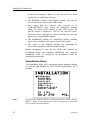
Instruction manual
Instruction Manual
This manual is intended as a reference guide for operating and
correctly installing the AP20 autopilot.
Great care has been paid to simplify operation and set-up of the
Simrad AP20, however, an autopilot is a complex electronic
system. It is affected by sea conditions, speed of the vessel, hull
shape and size.
Please take time to read this manual to get a thorough
understanding of the operation and system components and their
relationship to a complete AP20 autopilot system.
Other documentation material that is included in this manual is a
warranty card. This must be filled out by the authorized dealer that
performed the installation and mailed in to activate the warranty.
20220505H
1
Simrad AP20 Autopilot
Document revisions
Rev
–
A
B
C
D
E
Written by
Date
Sign
N.G.
22.03.97
N.G.
07.10.97
N.G.
22.06.98
N.G.
20.12.99
N.G.
27.03.00
N.G.
20.06.00
F
28.08.01
N.G.
G
15.05.02
N.G.
H
12.02.04
Checked by
Date
Sign
G.K.
22.03.97
Approved by
Date
Sign
Th.H.
22.03.97
Th.H.
07.10.97
Th.H.
22.06.98
Th.H.
20.12.99
Th.H.
27.03.00
Th.H.
20.06.00
28.08.01
15.05.02
I.K.
15.05.02
I.K.
Th.H.
12.02.04
Document history
Rev. –
First edition
Rev. A
Modified system drawings, Figure 1-1 and 4-1. Drawings for junction unit
terminal boards included. Page 18: Amendment to operational sequence of
R3000X. Description of AP300PX connection included. Modified
Installation menu, figure 4-28. NMEA sentence specifications included.
Quick reference guide included.
Rev. B
Course adjustment selectable between 1° and 10° per push with software
version V1R2 (page 19, 27, 32, 33 and 114). New structure for mounting
accessories, page 118. Minor correction of display screens on page 24, 25
and 88. FU35 Follow-up Steering Lever included on page 12. New
distributor list.
Rev. C
AP21 included on drawing page 55. Removed AP300P.
AP21 Connection on page 67 included. LFI3000 substituted by LFI3000
Mk2.
Rev. D
Modified note on page 117.
Rev. E
New art. no. on Robnet connectors, page 120. New gasket added on page 64
and under Standard mounting kit, page 118. Minor modifications in text.
Rev. F
IS11 instruments replaced by IS15. Added RPU300, 24V to the table on
page 58. CD100A included. Minor corrections to text and display pictures.
Rev. G
Updated according to software versions AP20 V1R3 and J300X V1R8.
Rev. H
Added note on page 70. Fig. 4-17 and 4-18 modified.
2
20220505H
Instruction manual
Contents
1
INTRODUCTION ....................................................................................... 8
1.1 General .................................................................................................. 8
1.2 How to use this manual......................................................................... 8
1.3 System components............................................................................... 9
1.4 AP20 Control Unit .............................................................................. 10
1.5 Junction units ...................................................................................... 10
1.6 RF300 Rudder Feedback unit ............................................................. 10
1.7 Heading Sensors.................................................................................. 10
RFC35 Electronic Fluxgate Compass................................................. 11
RFC35R Rate compass ....................................................................... 11
CDI35 Course Detector Interface and CD100A Course Detector...... 11
NMEA compass .................................................................................. 11
Other fluxgate compass models .......................................................... 11
Simrad RGC10 and RGC50 gyrocompasses ...................................... 11
1.8 Optional equipment............................................................................. 12
R3000X Remote Control .................................................................... 12
S35 NFU Lever ................................................................................... 12
FU35 Follow-Up Steering Lever ........................................................ 12
NI300X NMEA Interface Unit ........................................................... 12
CI300X Compass Interface................................................................. 12
2
Operation of the autopilot......................................................................... 13
2.1 Overview ............................................................................................. 13
2.2 ON/OFF - Standby mode .................................................................... 14
Flashing course knob icon .................................................................. 15
2.3 AP20 with MSD50 Stern Drive unit................................................... 15
Zero point setting ................................................................................ 15
Operation............................................................................................. 16
2.4 Follow-Up steering (FU)..................................................................... 16
20220505H
3
Simrad AP20 Autopilot
2.5 Non-Follow-Up steering (NFU) ......................................................... 17
2.6 R3000X Remote Control .................................................................... 18
2.7 S35 Steering lever ............................................................................... 18
2.8 Automatic Steering ............................................................................. 18
2.9 Automatic Speed selection.................................................................. 19
2.10 Manual speed selection ....................................................................... 20
2.11 Navigating with the AP20................................................................... 21
2.12 Selecting a different Navigator ........................................................... 23
2.13 Dodging............................................................................................... 24
2.14 Dodge in NAV .................................................................................... 25
2.15 TURN-mode........................................................................................ 25
2.16 Tacking in Auto mode ........................................................................ 26
2.17 Wind vane steering.............................................................................. 27
2.18 Tacking in Wind mode........................................................................ 28
2.19 Multiple station system ....................................................................... 28
2.20 Lock function ...................................................................................... 29
2.21 User Set-up Menu ............................................................................... 31
2.22 Instrument screens and menu.............................................................. 34
Instrument set-up................................................................................. 36
Flashing course knob icon .................................................................. 36
3
Technical Specifications ............................................................................ 37
3.1 AP20 Autopilot System ...................................................................... 37
3.2 AP20 Control Unit .............................................................................. 38
3.3 Junction units ...................................................................................... 40
3.4 RFC35 Fluxgate compass ................................................................... 42
3.5 RFC35R Rate compass ....................................................................... 43
3.6 CDI35 Course Detector Interface ....................................................... 43
3.7 RF300 Rudder Feedback..................................................................... 44
3.8 CI300X Compass Interface................................................................. 45
3.9 NI300X NMEA Interface ................................................................... 46
3.10 R3000X Remote Control .................................................................... 47
4
20220505H
Instruction manual
3.11 S35 NFU Steering Lever..................................................................... 47
3.12 NMEA messages................................................................................. 48
3.13 IP protection........................................................................................ 50
4
Installation.................................................................................................. 51
4.1 General ................................................................................................ 51
4.2 Installation checklist ........................................................................... 51
4.3 Unpacking and handling ..................................................................... 52
4.4 Determine system configuration ......................................................... 52
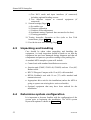
4.5 AP20 System Layout .......................................................................... 53
4.6 RF300 Rudder feedback installation................................................... 53
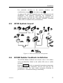
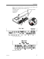
4.7 Junction unit installation ..................................................................... 55
4.8 Cable connections ............................................................................... 56
4.9 Grounding and RFI ............................................................................. 56
4.10 Drive unit installation.......................................................................... 58
Connecting a reversible pump ............................................................ 60
Connecting a hydraulic linear drive.................................................... 61
Connecting a solenoid valve ............................................................... 61
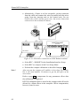
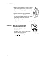
4.11 Control unit installation ...................................................................... 62
Panel mounting ................................................................................... 62
Alternative panel mounting................................................................. 62
Optional bracket mounting ................................................................. 63
4.12 ROBNET network cables ................................................................... 63
AP21 connection ................................................................................. 65
4.13 RFC35 Fluxgate Compass installation ............................................... 66
4.14 RFC35R Rate Compass installation.................................................... 67
4.15 R3000X Remote Control installation ................................................. 69
4.16 S35 NFU Lever installation ................................................................ 69
4.17 Interfacing ........................................................................................... 70
4.18 Single NMEA input/output ................................................................. 70
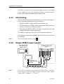
4.19 Double NMEA input/output ............................................................... 71
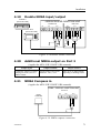
4.20 Additional NMEA output on Port 2.................................................... 71
20220505H
5
Simrad AP20 Autopilot
4.21 NMEA Compass in ............................................................................. 71
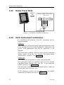
4.22 Radar Clock/Data................................................................................ 72
4.23 IS15 Instrument installation ................................................................ 72
4.24 External Alarm.................................................................................... 74
4.25 NI300X NMEA Interface Unit ........................................................... 74
4.26 CI300X Analogue Interface Unit........................................................ 76
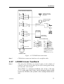
4.27 LF3000 Linear Feedback .................................................................... 77
4.28 CD100A Course Detector ................................................................... 79
4.29 CDI35 Interface................................................................................... 80
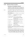
4.30 Software Setup Procedure................................................................... 81
Description of Installation Settings..................................................... 81
Installation Menu ................................................................................ 82
Language selection.............................................................................. 84
4.31 Dockside settings ................................................................................ 85
Drive unit voltage selection ................................................................ 85
Rudder Feedback Calibration ............................................................. 86
Automatic Rudder Test ....................................................................... 88
Transition Speed ................................................................................. 89
Interface Settings................................................................................. 90
4.32 Sea Trial .............................................................................................. 96
Rudder zero adjust .............................................................................. 96
Compass calibration............................................................................ 97
Compass Offset ................................................................................... 98
Automatic tuning................................................................................. 99
View parameters ............................................................................... 101
Manual parameter adjust................................................................... 101
NMEA Test ....................................................................................... 103
Display Units..................................................................................... 103
Master Reset...................................................................................... 104
Final sea trial ..................................................................................... 104
Providing user training...................................................................... 105
6
20220505H
Instruction manual
5
Maintenance ............................................................................................. 106
5.1 Control unit ....................................................................................... 106
5.2 Junction Unit ..................................................................................... 106
5.3 Rudder Feedback............................................................................... 106
5.4 Compass ............................................................................................ 106
5.5 Drive unit .......................................................................................... 106
5.6 Exchange of software programme .................................................... 107
6
Trouble shooting ...................................................................................... 109
6.1 Alarms ............................................................................................... 109
6.2 System Data Menu ............................................................................ 113
6.3 NMEA Data Menu ............................................................................ 114
Decoding ........................................................................................... 114
NMEA signal monitor....................................................................... 115
NMEA (hardware) test...................................................................... 116
7
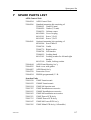
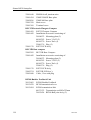
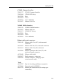
Spare Parts List........................................................................................ 117
8
Glossary .................................................................................................... 120
SALES AND SERVICE WORLDWIDE
TERMS OF WARRANTY
WARRANTY CARD
QUICK REFERENCE GUIDE
English
German
French
Italian
Spanish
Dutch
Swedish
Norwegian
20220505H
7
Simrad AP20 Autopilot
1
1.1
INTRODUCTION
General
Congratulations on the purchase of your new Simrad AP20
autopilot system and thank you for selecting what we feel is the
most advanced autopilot system available on the market today.
Today, Simrad manufactures a complete range of autopilots for
all types of vessels, from leisure boats to advanced steering
systems for merchant marine vessels. Our factory for these
products Simrad Egersund AS, is located in Egersund on the
southwest coast of Norway. The company's involvement in
autopilots began in 1953 with equipment for the North Sea
fishing fleet under the brand name Robertson. Professional
mariners around the world acknowledge that the Robertson and
Simrad brand names are synonymous with the absolute best in
autopilot technology.
The Simrad AP20 autopilot represents yet another step forward
in autopilot technology with the intent of providing leisure boats
between 30 and 80 foot with a host of new features. The system
can be expanded and enhanced with a selection of options and
accessories.
The brain in the AP20 autopilot system is the single "intelligent"
junction unit that communicates with all other system modules
on the ROBNET network. The ROBNET has been developed to
establish a reliable digital communication and power distribution
network between the units in the system. The ROBNET
simplifies installation and enables the AP20 system to be easily
expanded at any time.
1.2
How to use this manual
This manual is intended as a reference guide for operating,
installing and maintaining the Simrad AP20 autopilot. Great care
has been paid to simplify operation and set-up of the AP20,
however, an autopilot is a complex electronic system. It is
affected by sea conditions, speed of the vessel, hull shape and
size.
8
20220505H
Introduction
Please take time to read this manual to get a thorough
understanding of the operation and system components and their
relationship to a complete AP20 autopilot system.
Other documentation material that is provided with your system
includes a warranty card. This must be filled out by the
authorized dealer that performed the installation and mailed in to
activate the warranty.
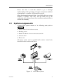
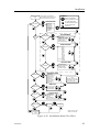
1.3
System components
A basic AP20 system consists of the following units (refer to
Figure 1-1):
• AP20 Control Unit with accessories
• Heading sensor
• Rudder Feedback Unit with transmission link
• Junction Unit
• Drive unit
The basic system can be expanded with remote control unit,
hand held remote and steering lever.
Figure 1-1 AP20 Basic system
20220505H
9
Simrad AP20 Autopilot
1.4
AP20 Control Unit
A compact autopilot control for panel, bulkhead or bracket
mounting. Large LCD display for readout of autopilot data and
rotary course knob. It has two Robnet connectors for system
interconnection and expansion.
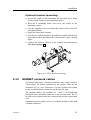
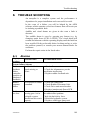
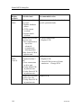
1.5
Junction units
The junction unit is the heart in the AP20 autopilot system. It
contains the steering computer, interface circuits to all system
components and drive circuits for the drive unit motor and
clutch. Three models, J300X, J300X-40 and J3000X are
available.
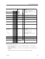
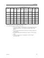
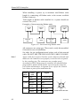
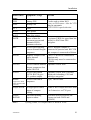
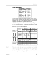
Junction unit comparison chart:
1.6
J3000X
J300X (J300X-40)
Supply voltage
10-28 V
10-40 V
Motor current
(continuous/peak)
6/10 A
10/20A (20/40A)
Clutch/bypass current
1,5 A
1,5 A
Number of control units
2
5
NMEA ports (input/output)
1
2
Solenoid output
x
x
Input for NFU control
x
x
External alarm
x
Radar clock/data interface
x
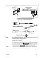
RF300 Rudder Feedback unit
Rudder feedback unit with transmission link and 10 m (30 feet)
of cable. Transforms the angular travel of the rudder to a digital
signal read by the autopilot steering computer.
1.7
Heading Sensors
The AP20 autopilot can be used with the following combinations
of heading sensors:
10
20220505H
Introduction
RFC35 Electronic Fluxgate Compass
A compact heading sensor from Simrad with 15 m (45 feet) of
cable. The direction of the earth's magnetic field is sensed by a
floating ring core in a fluxgate coil and transformed to a digital
signal read by the autopilot steering computer.
RFC35R Rate compass
Fluxgate compass with integrated rate sensor. Provides a dramatic
improvement to the dynamic performance of both the autopilot
and a stabilized radar display.
Same dimensions as RFC35.
CDI35 Course Detector Interface and
CD100A Course Detector
Interface and sensor unit to connect AP20 to a magnetic
compass. The AP20 provides excitation current for CD100A and
converts the analogue sin/cos signal to digital two wire format
for the autopilot steering computer.
Note !
You can not connect both an RFC35 and a CDI35 at the same
time.
NMEA compass
(Applies for AP20 V1R3/J300X V1R8)
Any NMEA 0183 compass with HDT, HDG or HDM messages
can be connected directly to the J300X/J300-40X junction units.
Other fluxgate compass models
The optional CI300X can interface AP20 to fluxgate compasses
with heading signal on a sine/cosine format.
Simrad RGC10 and RGC50 gyrocompasses
The optional CI300X unit is needed to interface the two
gyrocompass models. No other gyrocompass models can be
interfaced to AP20.
20220505H
11
Simrad AP20 Autopilot
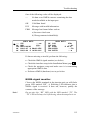
1.8
Optional equipment
A series of options are available for the basic AP20 system.
R3000X Remote Control
A small handheld remote control with two push buttons for
power steering or course selection (port and starboard), and one
push button with built-in lighted indicator for limited mode
change.
S35 NFU Lever
S35 is designed for indoor and outdoor bulkhead mount. The
lever has spring loaded return to mid-position. A push button
with light indicator is used for limited mode change.
FU35 Follow-Up Steering Lever
The FU35 Follow-up steering lever features a dial (scale) with
10° markings. The rudder will move and stop at the commanded
angle as read on the dial. FU35 has a mid-position detent, push
buttons for (limited) mode selection and mode indicators (STBY,
FU, AUTO and NAV). It is designed for indoor and outdoor
bulkhead or panel mount. See separate manual for FU35.
NI300X NMEA Interface Unit
Unit with 4 NMEA I/O ports for communication to other
systems, and a selectable heading output for radars (Anritsu or
Furuno). Includes two Robnet connectors for connection to the
AP20 system.
CI300X Compass Interface
Unit for interface to non-Simrad fluxgate compasses and
windvane systems with analogue output, and NFU levers. Input
for Simrad RGC50 and RGC10 gyro compasses.
12
20220505H
Operation
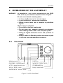
2
OPERATION OF THE AUTOPILOT
WARNING !
An autopilot is a very useful navigational aid, but DOES
NOT under any circumstance replace a human navigator.
Do not use automatic steering when:
• In heavy traffic areas or in narrow waters
• In poor visibility or extreme sea conditions
• When in areas where use of autopilot is prohibited
by law
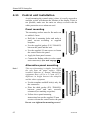
When using an autopilot:
• Do not leave the helm unattended
• Do not place any magnetic material or equipment
near heading sensor used in the autopilot system
• Verify at regular intervals course and position of
vessel
• Always switch to Standby mode and reduce speed
in due time to avoid hazardous situations
2.1
Overview
Multifunction LCD
PORT key
STANDBY / POWER on/off
DODGE/U-TURN/TACK
AUTO / manual speed select
STARBOARD key
NAV or WIND / setup
Rotary course knob
INSTRUMENT screens / menu
Figure 2-1 AP20 Front Panel
20220505H
13
Simrad AP20 Autopilot
The control unit shown above can operate as a stand alone unit
in an autopilot system or combined in a multistation system. In a
multistation system the command can easily be transferred from
one unit to another. Units not in control will display "Inactive".
The AP20 system is capable of the following primary steering
modes: STBY (manual steering), AUTO, NAV and WIND, each
mode having a dedicated push button.
Each of the mode push buttons is clearly identified with the
primary function in large text, and a secondary function listed in
smaller text. Each button provides you with the ability to access
a primary display, a secondary display and/or multiple function
displays.
A group of user adjustable settings are provided in the AP20
USER SETUP MENU (page 31). The settings allows adjustment
of display visibility, selection of heading sensors, navigation and
position sources and the ability to select between automatic or
manual adjustable sea state filter.
Alarms are presented in plain text to alert you of system and
external data failure conditions. Alarms include both audible and
visual presentations. The alarm listing is on page 109.
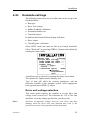
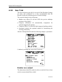
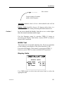
2.2
ON/OFF - Standby mode
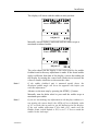
A single press on the STBY button switches the system ON and
the following status displays are shown:
Robertson
AP20
SW V1R3
HW rev. 0
Autopilot model
Software V(ersion) and R(elease)
Hardware revision
Robertson
J300X
P00
SW V1R8
M00 S000
Power board revision
Junction unit model
Software V(ersion) and R(elease)
Self check
Main board revision
SW and HW revisions shown are examples only.
14
20220505H
Operation
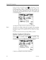
After approx. 5 seconds the system is operative and the unit that
was turned on will show the STBY mode display. Other units in
a multistation system will display "Inactive". Control can be
available at any unit by pressing the STBY button.
A long press (2-3 sec.) on the STBY button switches the system
OFF.
Note !
In an emergency it is possible on a multistation system to turn
OFF the system at any control unit by pressing down the STBY
button for 2-3 seconds.
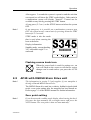
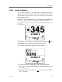
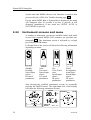
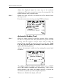
STBY mode is also the mode
that is used when steering the
boat at the helm.
Display information:
Standby mode, current heading
345° and rudder angle 2° to
starboard.
P
RUDDER
02
S
Flashing course knob icon
When the course knob is used for settings etc., an
icon will flash on the screen to tell that no course
changes can be made unless you press the AUTO
button.
2.3
Note !
AP20 with MSD50 Stern Drive unit
The information in section 2.3 only applies if your autopilot is
driving a Simrad MSD50 Stern Drive.
The MSD50 Stern drive unit has a relative feedback signal which
needs a zero point setting after the autopilot has been turned on.
Refer to page 1-1 of the MSD50 manual for further information.
Zero point setting
Note !
20220505H
If you do not need a rudder angle display when leaving the dock,
just steer the boat manually on a straight course and press the
AUTO button. The zero point is then set auto-matically.
15
Simrad AP20 Autopilot
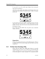
If you prefer to use the rudder angle display when leaving the
dock, proceed as follows:
After turn on the rudder angle display will alternate between 10
degrees port and starboard to indicate that the "rudder" zero point
need be set.
P
RUDDER
10
S
Use the wheel to bring the "rudder" to midship position. Turn the
wheel from lock to lock (H.O. to H.O.) and count the exact
number of turns. Then start from one lock position and turn the
half number of turns.
Press AUTO and then STBY. The zero point is now set and the
display will show:
P
RUDDER
00
S
Operation
Follow the operating instructions on the following pages. There is
no further need for zero point settings until next time you turn the
autopilot on.
2.4
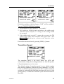
Follow-Up steering (FU)
When both the PORT and STBD push buttons are pressed
simultaneously the AP20 is set to Follow-Up steering mode and
rudder commands can be set by the course knob. One revolution
of the knob equals 44° rudder command. The commanded rudder
16
20220505H
Operation
angle is shown on the display and the rudder will move to the
commanded angle and stop.
HEADING
P
Press both buttons
simultaneously to
activate Follow-Up
S
P
Use course knob to
command rudder angle
WARNING:
While in Follow-Up mode,
you cannot take manual
control of the wheel.
Return to manual control
in STBY by pressing:
P
o
S
02
RFC
RUDDER
S
STBY
PWR
Actual rudder angle
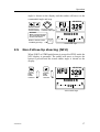
2.5
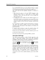
Non-Follow-Up steering (NFU)
When PORT or STBD push button is pressed in STBY mode the
NFU display is presented. The rudder will move as long as the
button is pressed and the actual rudder angle is shown on the
display.
HEADING
Activates
PORT
Rudder
command
Activates
STBD
Rudder
command
o
RFC
P
RUDDER
02
S
Actual rudder angle
20220505H
17
Simrad AP20 Autopilot
2.6
R3000X Remote Control
REMOTE
Push buttons for Port and
Stbd NFU commands
STBY-AUTO
STBY/AUTO mode button.
AUTO mode is when lamp is lit
In STBY mode the rudder will
move as long as the Port or
Stbd button is pressed.
In AUTO mode, the set course
will change 1° each press.
Note!
If you keep the button pressed,
it will automatically change the
course at a rate of 3°/second.
Operation of mode button
cycles the pilot as follows:
AUTO → STBY → AUTO
NAV → STBY → AUTO*
R3000X
* NAV mode can only be
entered from the Control unit.
2.7
S35 Steering lever
The principle is similar to that of R3000X Remote Control (see
above). The rudder will move as long as the lever is offset to
Port or Starboard.
Note !
2.8
When a NFU steering lever or remote control is operated, the
control unit(s) become "Inactive".
Automatic Steering
The AUTO mode is used to make the AP20 steer the boat
automatically on a set course. AUTO is always available from
any mode or function within the AP20 by a single press on the
AUTO button. When changing from STBY to AUTO mode, the
AP20 uses the current boat heading as the set course and the
simultaneous rudder angle. This gives a bumpless transfer at the
mode change.
In AUTO, the AP20 is issuing rudder commands to keep the
boat on the set course. Heading input is provided by the compass
for course keeping in AUTO mode.
18
20220505H
Operation
The AP20 will keep the boat on the set course until a new mode
is selected or a new course is set with either the course knob or
the PORT or STBD buttons. One revolution of the course knob
equals 44° course change.
Once the course is changed to a new set course, the boat will
automatically turn to the new heading and continue to steer the
new set course.
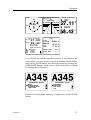
Decrease Increase
Course adjust
1°(or 10°)/push
Course change
CW: Increase
CCW: Decrease
Set course: 345 degrees
Compass heading: 340 degrees
Rudder angle: 2 degrees to stbd.
Speed input source: LOG
Speed parameter: HI
Regain manual
steering by
pressing:
Note !
2.9
HEADING
340
RFC
o
P
RUDDER
02
S
LOG -HI
STBY
PWR
The 10° course adjust by port or stbd button is available from
software version V1R2 onwards (see page 33).
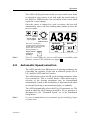
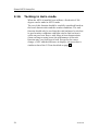
Automatic Speed selection
The AP20 provides two different sets of steering parameters for
controlling the response of the boat at different speeds (HI or
LO) while in AUTO and NAV modes.
The AP20 always selects the HI speed steering parameters when
first switched on. This is a safety feature. After initial turn on,
selection of the steering parameters may be accomplished
automatically, based on the availability of input data from either
an external speed log or an external navigator, or manually.
The AP20 automatically selects the HI or LO parameter set. The
speed at which the AP20 changes from HI to LO (or opposite) is
determined by the "Transition Speed" set in the Installation
Setup Menu.
Note !
20220505H
It is not recommended to use automatic speed switching if input
is from Loran.
19
Simrad AP20 Autopilot
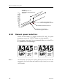
26
24
22
20
18
16
14
12
10
8
6
4
2
0
Example of
Transition speeds with
AUTOMATIC Speed parameter
selection
HI
ed
spe
LO
e
spe
ters
me
ara
p
d
Transition to HI parameters
with increasing speed: 10 Knots
rs
ete
am
par
Transition Speed set to 9 Knots
Transition to LO parameters
with decreasing speed: 8 Knots
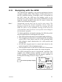
2.10
Manual speed selection
Select AUTO mode. To toggle between HI and LO speed
parameters, press the "AUTO" button two times quickly.
If you change boat speed it is recommended that you select HI or
LO parameters correspondingly.
AUTO
SPEED
HEADING
345
RFC
Note !
20
o
P
RUDDER
00
LOG -HI
S
HEADING
Quick
double
press
345
RFC
o
P
RUDDER
00
S
LOG -LO
The manually selected speed setting (HI or LO) will override the
automatic speed selection and remain in effect until you re-enter
AUTO mode.
20220505H
Operation
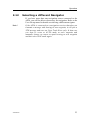
2.11
Navigating with the AP20
The AP20 has the capability to use steering information from an
external navigator (GPS, Chart Plotter) to direct the boat to a
specific waypoint location, or through a route of waypoints. In
the NAV mode, the AP20 uses the heading sensor as it's
reference for course keeping. The steering information received
from the external navigator alters the set course to direct the
AP20 to the destination waypoint.
Note !
Navigational steering must only be used in open waters. The
process of having an external navigation receiver direct an
autopilot can be a slow acting process. By selecting the NAV
mode, the AP20 is set for automatic steering on the current set
course and then waits for the user to accept the course change to
the destination waypoint.
To obtain satisfactory navigation steering, the following points
must be fulfilled prior to entering the NAV mode:
• The AP20 autosteering must be tested and found satisfactory.
• The navigation receiver must be operating and the navigation
system (GPS, Chart Plotter) must be in full operating mode
with adequate signal characteristics for valid position and
steering data.
• At least one waypoint must be entered and selected as the
current waypoint in the navigation receiver.
• The navigation source in the AP20 USER SETUP menu must
be set for the navigator that contains the current waypoint.
The AP20 is designed to steer in “mixed mode” operation. This
combines the straight steering capability of cross track error
(XTE) steering in conjunction with the turning capability of
bearing mode steering (Course To Steer, CTS).
WP Egersund
Press
Brg.
N AV
SETUP
to activate prompt display
Chg.
350 oo
OK ? Press NAV
HEADING
340
RFC
20220505H
RUDDER
P
S
00
LOG -HI
21
Simrad AP20 Autopilot
Press again to
activate NAV mode
CTS
NAV
SET UP
o
348
Display readout:
Course to steer: 348
Cross track error: .02 nm to stbd.
Compass heading: 347 M or T
Next waypoint: Egersund
Bearing to waypoint: 350
Distance to waypoint: 7.2 nm
HEADING
347
o
RFC
nm
NEXT WP
EGERSUND
o
BRG 350
DST
M
nm
* Course to steer is the course set internally in the autopilot to
steer the boat on to the track.
When operating the AP20 in NAV mode to automatically steer
through a route of waypoints, the AP20 will steer to the first
waypoint in the route after you accept the first waypoint as the
location to steer to. When you arrive at the waypoint, the AP20
will give an audible warning and display an alert screen with the
proposed new course information displayed. If the required
course change is more than 10° you will need to verify that the
upcoming course change is acceptable. Verification is performed
by pressing the NAV button after the alert screen is displayed. If
no verification is received, the AP20 will continue on the current
set course in AUTO mode.
At the arrival of each new
waypoint in a route:
Verify course change greater
than 10 by pressing:
Regain manual steering
at any time by pressing:
WP
Fishing
Brg.
N AV
SETUP
S TB Y
PWR
Chg.
100 oo
035
OK ? Press NAV
NEXT WP
HEADING
Fishing
135
RFC
BRG
o
M
DST
nm
Origin
New heading accepted
automatically after
NAV/SETUP button is pressed
Waypoint 1
Waypoint 2
Waypoint arrival zone
(determined by the navigator)
22
20220505H
Operation
2.12
Selecting a different Navigator
If you have more than one navigation source connected to the
AP20, you will be able to choose any for navigation. Refer to the
User Set-up menu for details on selecting a different navigator.
Note !
20220505H
If the AP20 is connected to a navigation receiver that does not
transmit a message with bearing to next waypoint, it will pick a
XTE message and steer on Cross Track Error only. In that case
you have to revert to AUTO mode at each waypoint and
manually change set course to equal bearing to next waypoint
and then select NAV mode again.
23
Simrad AP20 Autopilot
2.13
Dodging
Dodging is useful in situations where you need to quickly take
control of the helm to steer around an obstruction, and then wish
to return to the previous set heading after performing the evasive
manoeuvre. Dodging is activated by a quick press on the
DODGE button.
When in DODGE mode the displayed set course is the last one
set prior to activating the dodge function. When DODGE is
displayed, the AP20 is no longer in control of the steering, and
you must either manually steer the boat in STBY mode or take
control using Non Follow Up or Follow Up steering. On manual
steering (STBY mode) the clutch or bypass valve in the drive
unit will be disengaged. The AP20 will remain in the DODGE
mode until you exit DODGE by a second press on the
TURN/DODGE button or select another mode.
Press to activate Dodge mode:
Perform dodge using:
D OD GE
TURN
Wheel
DODGE
A336 o
HEADING
or
Non Follow Up
Follow Up
both
D OD GE
TURN
347
RFC
RUDDER
P
S
02
LOG -HI
Selects AUTO mode at the last set course
Next press
AUTO
SPEED
Note !
24
Selects AUTO mode with current heading as set course
Using NFU or FU sub modes while dodging will make “NFU”
or “FU” flash instead of “DODGE”.
20220505H
Operation
2.14
Dodge in NAV
Press to activate Dodge mode:
Perform dodge using:
DOD GE
DODGE
N 0.1nm
TURN
Wheel
HEADING
or
Non Follow Up
Follow Up
both
347
RFC
NEXT WP
Fishing
350 o
DST 7.2 nm
BRG
To return from Dodge mode press one of the following buttons:
ANUAV
TO
SP
EE
TE
UD
P
AUTO
SPEED
D OD GE
TURN
2.15
Selects NAV mode at present position with
new bearing to waypoint
Selects AUTO mode with current heading as set course
Returns to NAV mode at the current track
(not recommended as it may result in a big course change)
TURN-mode
The AP20 provides a special U-turn feature when in AUTO
mode. This feature is very useful in a man overboard situation.
U-Turn changes the current set course to be 180 degrees in the
opposite direction. The user may decide if the U-Turn should be
made to Port or Starboard to bring the boat on the new course.
U-Turn is activated by a quick double press on the DODGE
button. The AP20 will continue on the set course until you press
either the PORT or STBD button to select the direction to make
the U-Turn. If you do not press PORT or STBD within 1 minute,
the AP20 will return to the AUTO mode and stay on course.
Quick double press
to enter TURN mode
DODGE
DODGE
TURN
TURN
U-TURN
PORT
Press to select STBD U-turn
HEADING
Boat makes STBD U-turn
RFC
20220505H
PRESS
STBD
RUDDER
P
00
S
LOG -HI
25
Simrad AP20 Autopilot
2.16
Tacking in Auto mode
When the AP20 is installed on a sailboat, a fixed tack of 100
degrees can be made in AUTO mode.
The use of this function should be carefully considered based on
the boat's characteristics and the weather conditions. The tack
function should only be used into the wind and must be tried out
in good weather conditions with light wind to find out how it
works on your boat. Due to wide range in boat characteristics
(from cruising to racing boats) the performance of the tack
function may vary from boat to boat. Except for the course
change of 100° and the difference in displays, the procedure is
similar to that of the U-Turn described on page 25.
26
20220505H
Operation
2.17
Wind vane steering
Prior to entering WIND mode the AP20 system should be
operating in AUTO, with valid input from the selected wind
transducer. The WIND mode is an alternative function to the
NAV mode and it is only available if the system has been set up
for SAIL-boat in the Installation Menu, and NAV/WIND source
is set to WIND under the USER SETUP menu. (Refer to page
31).
WIND function can only operate when reaching as it is
necessary to have a stable apparent wind. The sails should be
trimmed so that the autopilot easily can steer the boat in AUTO
mode and the wind transducer must give a stable signal.
Enter the WIND mode by pressing the NAV/SETUP button.
The pilot will read the apparent wind angle at the moment the
WIND function is selected and enter it as the set apparent wind
angle. From that point the pilot will change the course to
maintain this apparent wind angle as the wind direction may
change.
Note !
If the cumulative shift of the apparent wind exceeds 15° from the
value at the time the WIND mode was selected, a WIND SHIFT
alarm will sound.
The display will show the set apparent wind angle. Adjustments
to this set angle can be done by using PORT or STBD button or
the rotary course knob.
The display is also presenting current heading and rudder angle.
Dodging while in the WIND mode is very similar to dodging
while in the AUTO or NAV modes. Refer to DODGE mode
operation in the AUTO mode section on page 24.
Increase Decrease
Adjust set
wind angle
1° (or 10°)/push
Wind angle adjust
CW: Decrease
CCW: Increase
Set apparent wind angle: 50 from stbd.
Compass heading: 347
Rudder angle: 2 to stbd.
Speed input source: LOG
Speed parameter: HI
Regain manual
steering by pressing:
Note !
20220505H
STBY
HEADING
347
RFC
o
P
RUDDER
02
S
LOG -HI
PWR
The 10°/step wind angle adjust by port or stbd button is
available from software version V1R2 onwards (See page 33).
27
Simrad AP20 Autopilot
2.18
Tacking in Wind mode
In WIND mode on sailboats there is also a tacking aid function.
This function may only be used when the boat is reaching and
will when activated take the boat from the course you are
steering to the computed course that gives you the same apparent
wind on the other side.
This tacking function as compared to tacking in AUTO mode
can only be used when you are sailing with the apparent wind as
the reference (WIND mode), and with apparent wind angle less
than 80-90 deg.
A quick double press on DODGE will activate the tack function
which will prompt you for which way the tack should be
performed. Press PORT or STBD to select the tack.
Quick double press to
activate tack function
TACK
DODGE
DODGE
TURN
TURN
Press to select
STBD Tack
PORT
HEADING
W
RFC
H
02
S
LOG-HI
H
50°
2.19
STBD
RUDDER
P
Boat makes
STBD Tack
W
PRESS
50°
Multiple station system
In normal operation of multiple control units, control is
accessible from every control unit connected to the AP20
system. One control unit is "active" and provides the user with
access to all functions and enables the user to change modes and
set the course for automatic course keeping. All remaining
control units are "inactive" and have no effect on mode changes
or course selection. A single press on any of the mode buttons on
an "inactive" control unit will allow transfer of command and
make it "active".
28
20220505H
Operation
2.20
Lock function
The "LOCK" function is a safety feature included in the AP20
system when you have more than one control unit installed. It
will disable all control units except for a single, user selected
control unit location.
When the "lock" function is in use, no transfer of command may
take place; only the "active" control unit stays in command.
To enable the "lock" function, make a quick double press on the
STBY button.
P
RUDDER
02
S
The display on the "active" control unit will first show a
and then the icon will alternate with the mode index.
icon
The "locked" control units in the system will show:
Inactive
P
RUDDER
02
S
The “Lock function is disengaged by the following actions:
• The “active” control unit unlocks by another double press on
the STBY button.
• The system is switched OFF by any control unit (press STBY
for 2-3 seconds).
20220505H
29
Simrad AP20 Autopilot
After having "unlocked" the other control stations, the "active"
control unit will show the above symbol before the display
returns to normal. All other control units will return to the
"inactive" state.
30
20220505H
Operation
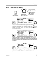
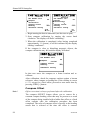
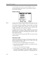
2.21
User Set-up Menu
Sequences
FWD in MENU
NAV
BACK
SETUP
Quick double press
to enter
User Setup Menu
NAV
SETUP
FWD
Sequences
BACK in
MENU
Scrolls through menu
selections or sets
value on menu items
SETUP
Nav/Wind
Backlight
Contrast
Nav Source
Seastate Filter
Nav
------MAN 1
The Nav/Wind selection only appears if the autopilot is
configured for sailboat. (See Dockside settings, page 85). Selects
whether NAV mode button will activate NAVigation mode or
WIND mode steering.
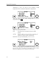
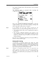
SETUP
Nav/Wind
Backlight
Contrast
Nav Source
Seastate Filter
Nav
------MAN 1
Adjust backlight of display and pushbuttons (10 steps, 10 =
brightest). Setting is stored when system is turned off, and resets
to stored level at turn on. Adjustment is local to the control head
you adjust.
SETUP
Nav/Wind
Backlight
Contrast
Nav Source
Seastate Filter
Nav
------MAN 1
Adjust contrast of displays (10 steps). Setting is stored when
system is turned off, and resets to stored level at turn on.
20220505H
31
Simrad AP20 Autopilot
Adjustment is local. All steps are not available at high
temperatures due to automatic temperature compensation.
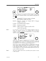
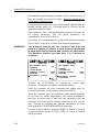
SETUP
Nav/Wind
Backlight
Contrast
Nav Source
Seastate Filter
Nav
GPS1
MAN 1
Select the source for NAV mode steering. Refer to interface
setup table on page 94.
SETUP
Nav/Wind
Backlight
Contrast
Nav Source
Seastate Filter
Nav
GPS1
MAN 1
Select value for Sea State Filter.
OFF:
Provides precise steering but increases rudder
activity.
AUTO:
Reduces rudder activity and reduces sensitivity of
autopilot in rough weather automatically.
MANUAL: Sets yaw band manually (1-10, 10 ≈ ±6°).
SETUP
Pos Source
Select Compass
Course adjust
System data
NMEA data
GPS1
RFC
1°
Select the source of speed over ground (SOG) and position data
processed by AP20. This option will only appear if there is more
than one navigation receiver connected to the system.
32
20220505H
Operation
SETUP
Pos Source
Select Compass
Course adjust
System data
NMEA data
GPS1
RFC
1°
Select the compass to be used for AUTO steering, if more than
one compass is connected. Refer to the interface setup table on
page 93.
RFC =
Simrad RFC35 Fluxgate compass or Simrad
RFC35R Rate compass (See Note)
MAGN = Magnetic compass (or Simrad RFC35 Fluxgate
Compass. (See Note)
FLUXG = Non-Simrad fluxgate compass
GYRO = Simrad gyrocompass
NMEA = NMEA compass (Applies for AP20 V1R3/
J300X V1R8 onwards)
Note !
It is necessary to select the correct compass and Nav. source to
make the autopilot operate. If a Simrad RFC35 Fluxgate
compass is used as backup to the RFC35R, it is selected when
MAGN is displayed.
SETUP
Pos Source
Select Compass
Course adjust
System data
NMEA data
GPS1
RFC
1°
When using the PORT or STBD buttons in automatic mode you
are changing the set course in 1° increments. If you prefer the
increments to be 10° each press, proceed as per below:
Select Course adjust using the PORT or STBD button. Turn the
rotary knob to display the setting. The default value is 1° which
is the preferred setting. Select 10° if you want to make major
course changes in 10° steps with the buttons and fine tune the set
course with the rotary knob.
Note !
20220505H
The course adjust menu item is available from software version
V1R2 onwards.
33
Simrad AP20 Autopilot
System data and NMEA data are test functions to analyse data
processed by the AP20. (See Trouble shooting page 109).
Except when NMEA data or System data is displayed, the menu
will disappear after 30 seconds if no key is pressed. It will
disappear immediately if any mode key (STBY, AUTO or
NAV/WIND) is pressed.
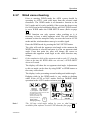
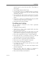
2.22
Instrument screens and menu
A number of instrument screens are available under each mode
screen if the required NMEA 0183 sentences are provided (see
paragraph 3.1). The instrument screen is activated by a single
press on the INSTR button.
Left hand side of the screen will show the following information
depending on mode:
347 o
123
LOG-HI
o
LOG-LO
Standby.
Heading.
Speed input
source.
HI speed
parameters.
Auto.
Set course.
Speed input
source.
LO speed
parameters.
0.12nm
045 o
LOG-HI
LOG-HI
Nav.
Cross Track
error.
Speed input
source.
HI speed
parameters.
Wind.
Set apparent
wind angle.
Speed input
source.
HI speed
parameters.
Step through the available instrument screens by repeatedly
pressing the INSTR button. The right hand side of the display
will show the following instrument screens:
SPEED
000
270
kt
347
090
RUDDER
S
DEPTH
RFC
P
02
34
20.1
14.4
ft
SHALLOW
WATER
20.1 ft
APPARENT
000
090
WIND
046 o
8
090
kt
180
20220505H
Operation
TRUE
WIND COG 274 M SOG 2.4 kt
BRG 272 M
WP
Egersund
D 32.2nm
X 0.02nm
000
046 o
8
270
090
DGPS1 POSITION
o
N 58
27.11'
E 005 o
kt
180
DGPS1 POSITION
N 58
E 005
27.20'
58.32'
COG 125 M
SOG 5.00kt
GPS1 NAV DATA
WP Egersund
BRG
034 M
DST 0.82nm
XTE 0.12nm
LOG
TOTAL
DISTANCE
3456
TRIP
DISTANCE
12.0
1.14
TRIP
TIME
ENGINE HOURS
WATER TEMP
nm
nm
hr
1420 hr
73
F
If you do not need all the instrument screens to be present in the
screen menu, you may remove screens by making a quick double
press on the INSTR button. Step through screens by pressing the
STBD/PORT buttons. Each screen can be removed or selected
by rotating the course knob.
INSTRUMENT SELECT
MAIN
SPEED/DEPTH
APPARENT WIND
TRUE WIND
INSTRUMENT SELECT
MOTORWAY
POSITION
NAV DATA
LOG
Return to last instrument screen by a simple press on the INSTR
button.
20220505H
35
Simrad AP20 Autopilot
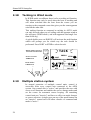
Instrument set-up
This screen gives access to the set-up of the Shallow Water
Alarm and the Trip reset. Press and hold the INSTRUMENT
button to activate the screen as shown.
INSTRUMENT SETUP
SET SHALLOW
--.--ft
RESET TRIP
--.--nm
--:--hr
Select item using the STBD [>] button and the course knob to set
the shallow water alarm limit. Also use the course knob to reset
the trip counter.
Note !
The shallow water alarm is activated only when digits are
dialled in.
The setting of the alarm is local. In a multistation system,
however, the setting representing the deepest water limit will
activate the alarm even if this setting is on an “inactive” unit.
Flashing course knob icon
When the course knob is used for settings etc., an
icon will flash on the screen to tell that no course
changes can be made unless you press the AUTO
button.
36
20220505H
Technical Specifications
3
TECHNICAL SPECIFICATIONS
3.1
AP20 Autopilot System
Boat size and type:..................... Up to 80 feet, Power, Displacement, Sail
Steering system types: ............... Hydraulic, Mechanical
Inter-unit connection: ................ ROBNET network or two-wire supply/data
System ON/OFF: ....................... From control units
Supply voltage:.......................... See junction units
Power consumption: .................. Dependent on system configuration
Environmental Protection:
Control Unit: ..................... IP56 from front, IP43 from back.
RFC35, RFC35R, CDI35: IP56
RF300: .............................. IP56
J300X:............................... IP44
NI300X, CI300X: ............. IP44
EMC protection: ........................ EN60945 : 1993, A1 : 1993
Automatic Steering control:
Rudder Drive: ................... Proportional rate or solenoid on/off
Parameter selection:.......... Automatic with manual override
Sea state control:............... Adaptive sea state filter or manual
Language selection: ................... English, Norwegian, French, Spanish, German,
Italian, Dutch, Swedish.
Electronic Interface:
Navigation interface:......... Standard (NMEA 0183)
NMEA inp./outp. ports: .... Max. 6 (see junction units and NI300X
specifications)
NMEA input sentences:.... APA, APB, BOD, BWC, BWR, BWW, DBK,
DBT, DPT, GGA, GLL, MTW, MWV, RMA,
RMB, RMC, VHW, VLW, VTG, VWR, XTE,
XTR, ZTG, ZDA, (PSTOE, PSTOI).
NMA output sentences: .... BWC, BWW, GLL, HDG, HDM, HDT, HSC,
RMB, RMC, RSA, VTG, XTE.
Optional output: ............... Anritsu and Furuno radar display (clock/data)
20220505H
37
Simrad AP20 Autopilot
Heading sensors:
Standard: ........................... RFC35 Electronic Fluxgate compass
Options:............................. Magnetic compass
RFC35R Rate compass
NMEA Compass (Not J3000X)
Simrad RGC50/RGC10 gyrocompasses *
Analogue fluxgate compass (sin/cos)*
Analogue wind vane (sin/cos)*
* By CI300X
Course Selection:....................... Rotary course dial and push button
Alarms: ...................................... Audible and visual, optional external
Alarm modes: ............................ Off course, system failures, overload
Steering modes: ......................... Standby, Non-follow up, Follow-up, Auto, Nav,
Wind
Special Turn modes: .................. Dodging, Tacking, U-Turn
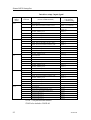
Instrument screen interface:
Instrument screen
NMEA messages
MAIN (HDG+RUDDER)
ROBNET™ PROPRIETARY
SPEED/DEPTH
VHW + DBK/DBT/DPT
APPARENT WIND
MWV/VWR
TRUE WIND
MWV/VWR + VTG/RMC/RMA
MOTORWAY
APB + RMB + VTG + GGA/RMC
POSITION
GGA/RMC/RMA
NAV DATA
APB + VTG/RMC + GGA/RMC + RMB/BWC
LOG
VLW + MTW + PSTOE (Proprietary
Robertson IS11 message for engine hours)
Note !
3.2
Alternative messages are separated by slashes.
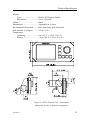
AP20 Control Unit
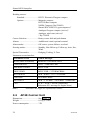
Dimensions: ............................... See Figure 3-1
Weight: ...................................... 0,5 kg (1.1 lbs)
Power consumption ................... 3 W
38
20220505H
Technical Specifications
Display:
Type: ................................. Backlit LCD matrix display
Resolution: ........................ 160 x 128 pixels
Colour: ....................................... Black
Illumination: .............................. Adjustable in 10 steps
Environmental Protection:......... IP56 from front, IP43 from back.
Safe distance to compass: .......... 0.5 m (1.6 ft.)
Temperature:
Operating: ......................... 0 to +55 °C (+32 to +130 °F)
Storage: ............................. –30 to +80 °C (–22 to +176 °F)
Figure 3-1 AP20 Control Unit – dimensions
(Mounting bracket is optional equipment)
20220505H
39
Simrad AP20 Autopilot
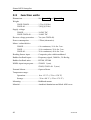
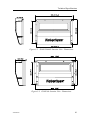
3.3
Junction units
Dimensions: ............................... See Figure 3-2 and Figure 3-3
Weight:
J300X/J3000X .................. 1,3 kg (2,9 lbs.)
J300X-40........................... 2,8 kg (6,2 lbs)
Supply voltage:
J3000X .............................. 10-28V DC
J300X/J300X-40 ............... 10-40V DC
Reverse voltage protection ........ Yes (not J300X-40)
Power consumption: .................. 5 Watt (electronics)
Motor / solenoid drive:
J3000X .............................. 6 A continuous, 10 A for 5 sec.
J300X ................................ 10 A continuous, 20 A for 5 sec.
J300X-40........................... 20 A continuous, 40 A for 5 sec.
Heading Sensor input: ............... Composite pulse width modulated
Rudder feedback input:.............. Frequency signal, 3400 Hz., 20 Hz/deg.
Rudder feedback units: .............. RF300, LF3000
NMEA input/output ports:......... J3000X: 1 (one)
J300X, J300X-40: 2 (two)
External Alarm: ......................... Open collector
Temperature range:
Operation: ......................... 0 to +55 °C (+32 to +130 °F)
Storage: ............................. –30 to +80 °C (–22 to +176 °F)
Mounting: .................................. Bulkhead mount
Material:..................................... Anodized aluminium and black ABS cover
40
20220505H
Technical Specifications
Figure 3-2 J300X/J3000X Junction Unit - Dimensions
Figure 3-3 J300X-40 Junction Unit - Dimensions
20220505H
41
Simrad AP20 Autopilot
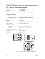
3.4
RFC35 Fluxgate compass
Dimensions: ............................... See Figure 3-4
Weight: ...................................... 0,9 kg (2,0 lbs)
Supply and output:..................... Polarity independent 2-wire supply with
superimposed pulse width modulation
Automatic Performance:
Calibration: ....................... Automatically activated by control head
Gain compensation: .......... Automatically adjusted continuously
Repeatability:............................. ± 0.5 degrees
Roll/Pitch:.................................. ± 35 degrees
Accuracy:................................... ± 3 degrees after calibration
Cable supplied: .......................... 15 m TP shielded cable
Temperature range:
Operation: ......................... 0 to +55 °C (+32 to + 130 °F)
Storage: ............................. –30 to +80 °C (–22 to +176 °F)
Environmental Protection:......... IP56
Mounting: .................................. Deck or bulkhead
Material:..................................... Black ABS
Figure 3-4 RFC35 Fluxgate Compass - Dimensions
42
20220505H
Technical Specifications
3.5
RFC35R Rate compass
Dimensions: ............................... See Figure 3-4
Weight: ...................................... 0,9 kg (2,0 lbs)
Supply and interface:................. Robnet
Power consumption: .................. 0,9 watts
Automatic Performance:
Calibration: ....................... Automatically activated by control head ....
Gain compensation: .......... Automatically adjusted continuously
Rate sensor stabilized heading output
Accuracy:................................... <1.25° (rms)
Repeatability:............................. <0.2° (rms)
Roll/Pitch:.................................. ± 35 degrees
Cable supplied: .......................... 15 m TP shielded cable
Temperature range:
Operation: ......................... 0 to +55 °C (+32 to + 130 °F)
Storage: ............................. –30 to +80 °C (–22 to +176 °F)
Environmental Protection:......... IP56
Mounting: .................................. Deck or bulkhead
Material:..................................... Black ABS
3.6
CDI35 Course Detector Interface
Dimensions: ............................... See Figure 3-5
Weight: ...................................... 0,9 kg (2,0 lbs)
Supply and output:..................... Polarity independent 2-wire supply with
superimposed pulse width modulation
Automatic Performance:
Calibration: ....................... Automatically activated by control head
Gain compensation: .......... Automatically adjusted continuously
Repeatability:............................. ± 0.5 degrees
Accuracy:................................... ± 0,5° (not including errors from course
detector)
Cable supplied: .......................... 15 m TP shielded cable
20220505H
43
Simrad AP20 Autopilot
Dimensions: ............................... 160 mm x 126 mm (6.3 in x 5 in.)
Weight: ...................................... 0,9 kg including cable (2,0 lbs.)
Power consumption: .................. 0,9 watts
Temperature range:
Operation: ......................... 0 to +55 °C (+32 to + 130 °F)
Storage: ............................. –30 to +80 °C (–22 to +176 °F)
Environmental Protection:......... IP56
Mounting: .................................. Deck or bulkhead
Material:..................................... Black ABS
Figure 3-5 CDI35 Course Detector Interface - Dimensions
3.7
RF300 Rudder Feedback
Dimensions: ............................... See Figure 3-6 and Figure 3-7.
Weight: ...................................... 0,5 kg (1,1 lbs)
Rudder angle:............................. ± 90 degrees
Output signal: ............................ Polarity independent frequency signal
Frequency resolution: ....... Centre: 3400 Hz, 20 Hz/degree of change
Linearity:........................... ± 3 degrees up to 45 degrees of rudder
Cable supplied: .......................... 10 m twisted pair shielded cable
Mounting: ................................. Horizontal, vertical, upside down
Material: .................................... Polyacetal (POM)
Environmental Protection:......... IP56
44
20220505H
Technical Specifications
Temperature range:
Operation: ......................... –10 to +55 °C (+14 to +130 °F)
Storage: ............................. –30 to +80 °C (–22 to + 176 °F)
Transmission link: ..................... Stainless 350mm (13.8") with 2 ball
joints. Ball joint stud for rudder arm
requires 4.2mm dia hole and 5mm tap.
Figure 3-6 RF300 Rudder Feedback - Dimensions
Figure 3-7 Transmission link - Dimensions
3.8
CI300X Compass Interface
Dimensions: ............................... See Figure 3-8
Weight: ...................................... 0,9 kg (2,0 lbs)
Power consumption: .................. 2 W
20220505H
45
Simrad AP20 Autopilot
Gyro compass input:.................. Synchro 1:1 (RGC10/RGC50 gyrocompasses)
Heading or windvane input: ...... Sin/cos max 12V DC
NFU steering lever input: .......... Port/stbd potential free contact
Robnet network interface: ......... 2 network connectors
Cable inlets: ............................... Rubber glands for cable diam. 10-14 mm
Mounting: .................................. Bulkhead mount
Material:..................................... Epoxy coated aluminium
Environmental Protection:......... IP44
Temperature range:
Operation: ......................... 0 to +55 °C (+32 to +130 °F)
Storage: ............................. –30 to +80 °C (–22 to +176 °F)
Figure 3-8 CI300X and NI300X - Dimensions
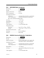
3.9
NI300X NMEA Interface
Dimensions: ............................... See Figure 3-8
Weight: ...................................... 0,9 kg (2,0 lbs)
Power consumption: .................. 3 W
NMEA183 input/output:............ 4 ports, max output load 20 mA
Heading output: ......................... Anritsu and Furuno radar display (clock/data)
NMEA instrument supply: ........ 12V DC, max 0.25A
Robnet network interface: ......... 2 network connectors
Cable inlets: ............................... Rubber glands for cable diam 10-14 mm
Mounting: .................................. Bulkhead mount
46
20220505H
Technical Specifications
Material:..................................... Epoxy coated aluminium
Environmental Protection:......... IP44
Temperature range:
Operation: ......................... 0 to +55 °C (+32 to +130 °F)
Storage: ............................. –30 to +80 °C (–22 to +176 °F)
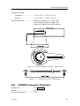
3.10
R3000X Remote Control
Dimensions: ............. See Figure 3-9
Weight:..................... 0,4 kg (0,9 lbs)
Protection ................. IP56
Cable length: ............ 7 m, shielded
Material:..........Epoxy coated aluminium
Figure 3-9 R3000X - Dimensions
3.11
S35 NFU Steering Lever
Dimensions: .................. See Figure 3-10
Weight: ......................... 1,4 kg (3,1 lbs)
incl. 10 m cable
Protection...................... IP56
Power consumption: .... 6 mA
Max. inductive load:..... 4A/12-24VDC
60mA/110VAC,
25mA/220VAC
Figure 3-10 S35 - Dimensions
20220505H
47
Simrad AP20 Autopilot
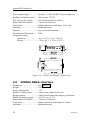
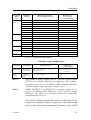
3.12
NMEA messages
Compass_Data
Compass heading, M
Compass heading, T
Rudder_Data
Rudder angle
Wind_Data
Apparent wind angle
Apparent wind speed
Depth_Data
Depth ref transducer
Transducer-Keel Offset
Depth range
Speed_Temp_Data
Speed through water
Log distance and trip
Water temperature
Gps_Data
Nav_Data
APB
BOD
VTG
p
ZDA
RMC
p
(APA)
GLL
p
n
n
n
2
2
1
N N N
N N
X
3
1
2
2
1
1
1
3
2
X*
X
1
1
1
4
3
1
2
1
3
2
4
1
2
5
2
1
3
1
4
3
To-wp position
To-wp ident.
From-wp ident.
Bearing wp-wp, T
Bearing wp-wp, M
Bearing pos-wp, T
Bearing pos-wp, M
Distance pos-wp
Time to go to dest. Wp
XTE
Waypoint closure velocity, VMG
Heading steering cmd, T / M
Light_Cmd
IS11 illumination
IS15 RX:
IS15 TX:
Transmission interval in sec.->
If Instr. port (ref instr setup)->
J3xx V1R7 onwards Channel2 TX:
Note !
p
P P P P P
P* P P P
Present position Lat, Long
COG, T
COG, M
Universal Time Coordinated (UTC)
Magnetic variation
x
SOG
Steering_contr1
J3xx RX:
J3xx TX:
J3xx TX:
p
RMA
VLW
Accept. cond. (N=no nav. flg warning, P= no pos. flg warning):
Status flag
GGA
VHW
DPT
MTW
c
DBT
h
(DBK)
h
(VWR)
RSA
h
MWV
HDT
Data source: (n/p/h=nav/pos/heading source, c=calculated):
HDG
Message ident.
(HDM)
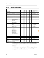
NMEA messages and data overview for IS15, AP11, AP20, AP35, AP300X, AP3000(X) and J3xx V1R8
6
5
x
x
x
x
x
x
x
1
.2
x
1
1
x
1
.2
1
.2
.1* 1
.1*
1
x
x
x
x
x
x
x
x
x
x
x
x
x
x
x
x
x
x
x
x
6
6
4
3
4
5
5
3
5
4
x
x
x
x
x
x
x
x
x
x
x
x
x
x
2
x
x
2
x
2
x
x
x
x
1. APB message may read in true or magnetic bearing wp-wp
and bearing pos-wp. These fields are sent as magnetic bearings
from IS15.
2. IS15. Magnetic variation from the HDG message is only used
to calculate true heading from the data in the same Hdg
message, and is not read in to the system.
48
7
20220505H
Technical Specifications
Remarks:
Indata use
n
n
n
n
n
N
N
N P
P
P
P
n
Bold red = {IS15, J3xx and IS11Multi} M=Multi
only, black = {J3xx and IS15}.
Blue 'X' IS15 only. Shadowed not to be used
any more
c
N/P=nav/pos data warning, *DGPS if flag=2
c
c
x
x
d,c
d,c*
d,c
d
d,c
d,c
d
d
*Not for AP35
* Output only
c
c
M M
1
1
4
3
2
3
1
2
1
1
1
d
d
d
d
x
x
x
x
x
HDG message in to IS15 see note2
x
x
x
x
x
x
x
x
Not in/out IS15
*Not for AP3000
c
d
d,c
d
d
d,c
d,c
d
d
d
d
d,c*
d
d*
d*
d
d
d
d
d
d
d
d
d
d
d,c
d,c
d,c
d
d
d
d
d
d
d,c
M
3
4
2
d*
d
2
2
2
d
d
d
3
3
1
2
X 1
3
1
x
x
x
10 10
x
x
x
x
x
x
2
x
5
x
x
x
x
x
x
x
IS15 sends bearing as magnetic
* Not for AP3000, wp-wp used if no pos-wp data
* Not for AP3000
x
x
1
x
IS15 sends bearing as magnetic
x
x
x
x
x
10
d = displayed
c= used in calc.
* HDG out if magn. sensor, HDT out if true sensor
Proprietary sentences in/out IS15:
−
In to IS15 $PSTOK,a<CR><LF> Status of compass calibration: a = I:init, R:running,
F:failed, C:calibrated.
−
Out from IS15: $PSTOK,,,x.x,*XX<CR><LF> Set compass offset. x.x is offset angle, 0 to
360 degrees.
−
Out from IS15: $PSTOC,*77<CR><LF> Sent start calibration of compass.
20220505H
49
Simrad AP20 Autopilot
3.13
IP protection
Each part of a Simrad autopilot system has a two digits IP
protection code.
The IP rating is a method to classify the degree of protection
against solid objects, water ingress and impact afforded by
electrical equipment and enclosures. The system is recognised in
most European countries and is set out in a number of British
and European standards.
The first code number describes the protection against solid
objects, and the second number describes the protection against
liquids.
FIRST NUMBER
Protection against solid
objects
50
SECOND NUMBER
Protection against liquids
IP TESTS
IP
TESTS
0
No protection
0
No protection
1
Protection against solid
objects up to 50 mm, eg.
accidental touch by hands.
1
Protected against vertically falling
drops of water (eg. condensation).
2
Protection against solid
objects up to 12 mm, eg.
fingers.
2
Protected against direct sprays of water
up to 15° from the vertical.
3
Protection against solid
objects over 2.5 mm (tools +
wires)
3
Protected against sprays to 60° from the
vertical.
4
Protection against solid
objects over 1 mm (tools +
wires + small wires)
4
Protected against water sprayed from
any direction.
5
Protection against dust limited ingress (no harmful
deposit)
5
Protected against low pressure jets of
water from all directions - limited
ingress permitted.
6
Totally protected against
dust
6
Protected against strong jets of water,
eg. for use on shipdecks - limited
ingress permitted.
7
Protected against the effects of
immersion between 15 cm and 1 m.
8
Protected against long periods of
immersion under pressure.
20220505H
Installation
4
INSTALLATION
4.1
General
This section provides detailed information
successfully installing AP20 Autopilot system.
required
to
The AP20 system includes several modules that need to be
mounted in different locations on the boat, and also need to
interface with at least three different systems on the boat:
• The boat's steering system
• The boats electrical system (input power)
• Other equipment on board (NMEA interfacing)
In addition, the advanced capabilities of the AP20 require the
installer to perform a series of settings and tests to verify proper
operation of the system, refer to the check list below.
4.2
Installation checklist
1. Determine system configuration you are installing (Page 52)
2. Perform the hardware installation (Page 53)
3. Connect external NMEA devices (inputs and outputs, page
70)
4. Set Language (Page 84)
5. Dockside settings (Page 85)
a) Boat type selection.
b) Drive unit selection.
c) Rudder feedback calibration.
d) Automatic rudder test.
e) Transition Speed
6. Interface setup for Junction Unit and NI300X/CI300X if
installed (Page 90)
7. Perform settings in User Setup Menu page 31, for NAV
source, POS source and Compass source
8. Dockside Autopilot tests (refer to Operating Instructions,
page 13)
a) Test all stations (if applicable) - lock/unlock - active/
inactive
b) Test Non-Follow Up mode
c) Test Follow-Up mode
d) Test AUTO mode
20220505H
51
Simrad AP20 Autopilot
e) Test NAV mode and input interfaces (if connected)
including optional heading sensors
f) Test interface outputs to external equipment (if
connected)
9. Seatrial settings (Page 96)
a) Set rudder zero
b) Compass calibration
c) Compass Offset adjustment
d) Automatic tuning (Optional: does not need to be done)
e) Viewing parameters
10. Testing Autopilot Operation at Sea (refer to Sea Trial
instructions, pages 96, 104)
11. Provide the user with training (Page 105)
4.3
Unpacking and handling
Care should be taken when unpacking and handling the
equipment. A visual inspection should be made to see that the
equipment has not been damaged during shipment and that all
components and parts are present according to the packing list.
A standard AP20 autopilot system will include:
• Control unit with standard installation accessories.
• Junction unit (J300X, J300X-40, J3000X) and one 15 m (49')
Robnet cable.
• RFC35 Fluxgate Compass with 15 m (49') cable attached.
• RF300 Feedback unit with 10 m (33') cable attached and
transmission rod.
• Appropriate drive unit for the installation (unless the AP20 is
going to operate an existing drive unit or solenoids).
• Optional equipment that may have been ordered for the
installation.
4.4
Determine system configuration
It is important to become familiar with the configuration of the
system prior to beginning the installation. The AP20 system
layout with options is shown in Figure 4-1
52
20220505H
Installation
Pay particular attention to the junction unit/drive unit
combinations on page 58 and the chart on page 10.
As many of the units are communicating on a common network
(ROBNET), with identical connectors, the installation is
simplified. Try to mount the units within the standard cable
length supplied with each unit, if possible. ROBNET Extension
Cable (10m) is available from your distributor.
4.5
AP20 System Layout
Figure 4-1 AP20 system layout with options
4.6
RF300 Rudder feedback installation
The RF300 Rudder feedback unit mounts close to the rudder,
and is mechanically linked to the rudder tiller arm or rudder
quadrant.
Refer to Figure 4-2 for the recommended mounting arrangement.
Note that the RF300 transmitter arm has two slots for the
transmission link. The slots enable maximum flexibility to
provide the 1:1 mechanical linkage relationship.
20220505H
53
Simrad AP20 Autopilot
Note !
Do not try to remove the transmitter arm from the feedback unit.
The unit is factory adjusted and need no further adjustment at
installation than described below.
As a starting point, it is desirable to set the transmitter rod to the
inner limit of the outer slot if possible. (Refer to Figure 4-2).
Drill and tap the rudder tiller arm so that the Y1 dimension is
equal to the Y2 dimension (Use 4.2 mm drill and 5 mm tap).
Attach the ball joint to the tiller arm, and connect the transmitter
rod to the ball joint at the rudder tiller arm.
Turn the helm wheel to set the rudder tiller arm to approximate
centre position.
Rotate the RF300 transmitter lever until it is set to centre
position. (Use the alignment mark to line up the transmitter lever
to be opposite the cable entry into the feedback.).
Note !
Carefully observe the alignment marks. A rudder feedback alarm
may be the result if the alignment instructions as per Figure 4-2
are neglected.
Attach the transmitter rod to the RF300. Set the RF300 mounting
location to be in accordance with Figure 4-2. The centre of the
RF300 should be in line with the centre of the rudder post.
Mount the RF300 to a suitable platform using the screws
provided. If necessary, add blocking material under the RF300 to
adjust the height of the transmission arm to be level with the
rudder tiller arm.
Figure 4-2 RF300 mounting (019356)
54
20220505H
Installation
Note !
Due to space limitations, it may be necessary to cut the length of
the transmitter rod to move the RF300 closer to the rudder post.
Tighten the mounting screws for both the RF300 feedback unit
and the transmitter rod ball joint.
Observe the RF300 while someone turns the helm wheel through
the complete travel from full port to full stbd. rudder to verify
that the mechanical linkage to the RF300 is not obstructed.
JUNCTION UNIT
MAIN PCB
RF
RF +
Rudder
Feedb.
*
* NON POLARIZED
(COLOR INDEPENDENT)
Figure 4-3 RF300 connection
4.7
Junction unit installation
The junction unit is
designed to operate in a
location that provides
ambient
temperatures
below +55°C (+130°F).
Note !
The
junction
units
(J3000X, J300X and
J300X-40)
are
not
weatherproof and should
be mounted vertically as
shown in a dry place
between the control unit
and the drive unit.
Figure 4-4 J3XX mounting
20220505H
55
Simrad AP20 Autopilot
4.8
Cable connections
Use only shielded cables. This includes Mains input, drive units
and if necessary for the extension of the RF300 Rudder
Feedback cable. The clutch/bypass cable and the solenoid cable
should be 1,5 mm2 (AWG14). Signal cables should be 0.5 mm2
(AWG20) twisted pairs.
The mains supply cable and the drive unit motor cable should
have sufficient wire gauge. This will minimize voltage drop and
allow the drive unit to operate at full power.
Refer to the table below for recommended cable sizes.
Cable length
1. Breaker panel to Junction Unit.
2. Junction Unit to Drive Unit motor
(Length refers to each of the two cables)
4.9
Drive Unit Voltage
12 V
24V
AWG
mm2
AWG
mm2
Up to 3 m (10 ft.)
12
2,5
12
2,5
Up to 6 m ( (20 ft.)
10
4
10
2,5
Up to 10 m (32 ft.)
8
6
10
4
Up to 16 m (52 ft.)
6
10
8
6
Grounding and RFI
The autopilot system has excellent RFI protection and all units
use the Junction Unit as a common ground/shield connection.
The Junction Unit should therefore have a proper ground
connection to the hull/bonding system.
ROBNET cables and other signal cables (compass, feedback,
NMEA) should not be run in parallel with other cables carrying
RF or high current, such as VHF and SSB transmitters, battery
chargers/ generators, winches and thrusters.
Remove the bottom cover to get access to the plug-in terminals.
Strip about 1 cm (0.4") of the cable's insulation and pull the
screen backwards to cover the insulation. Position the straps as
shown and tighten well to make sure the screen has good
contact.
Provide sufficient wire length so that the plug-in terminals can
be easily connected/disconnected.
56
20220505H
Installation
Pull out each terminal before connecting the wires. Remove all
Note! before putting on the terminal cover.
strands
Ground terminal
The Mains input
is not polarity
protected on
J300X-40.
TB9 and TB10 are not on the
J3000X Power Board
Power Board terminals
Main Board terminals
20220505H
57
Simrad AP20 Autopilot
4.10
Drive unit installation
The relation between drive units, drive unit voltage, input
voltage, drive output and interfacing to steering gear are shown
in the table below. The AP20 system detects whether a reversible
motor or a solenoid is connected and outputs the correct drive
signal automatically.
Refer to the connecting diagram for the different drive units on
page 60 onwards.
Installation instruction for the drive units are found in the
manual for the individual units.
The maximum drive current capability of the J3000X, J300X
and J300X-40 junction units are different. Use the table below as
reference and observe the notes on next page.
HYDRAULIC PUMPS
RAM CAPACITY
FLOW RATE
AT 10 bar
cm3/min
(cu. in/min)
MAX
PRESSURE
bar
PWR.
CONSUMPTION
250
(15,2)
800 (49)
50
2,5-6 A
160 (9,8)
550
(33,5)
1600 (98)
60
3-10 A
J300X
190
(11,6)
670
(40,8)
2000 (122)
80
3-10 A
12V
J300X-40
290
(17,7)
960
(58,5)
3000 (183)
60
5-25 A
RPU300
24V
J300X
290
(17,7)
960
(58,5)
3000 (183)
60
2,5-12 A
RPU3
24V
J3000X
370
(22,4)
1700
(103)
3800/5000
(232/305)
40
7-22 A
RPU1
12V
J3000X
140 (8,5)
600
(36,6)
1400/2000
(120/185)
40
7-22 A
MODEL
MOTOR
VOLTS
JUNCTION
UNIT
RPU80
12V
RPU160
MIN
cm3
(cu. in.)
MAX
cm3
(cu. in.)
J3000X
80 (4,9)
12V
J300X
RPU200
24V
RPU300
Steering gear interface: Hydraulic plumbing
58
20220505H
Installation
LINEAR DRIVE UNITS
MOTOR
VOLTS
JUNCTION
UNIT
MAX
STROKE
mm (in.)
PEAK
THRUST
kg (lb.)
MAX
RUDDER
TORQUE
Nm
(lb.in.)
HARDOVER
TIME
sec.
(30% load)
PWR.
CONSUMP.
TILLER
ARM
mm
(in.)
MLD200
12V
J3000X
300 (11,8)
200
(440)
490
(4350)
15
1,5-6 A
263
(10,4)
HLD350
12V
J3000X
200 (7,9)
350
(770)
610
(5400)
12
2,5-8 A
175
(6,9)
HLD2000L
12V
J300X
340 (13,4)
500
(1100)
1460 (12850)
19
3-10 A
298
(11,7)
HLD2000D
24V
J300X
200 (7,9)
1050
(2310)
1800
(15900)
11
3-10 A
175
(6,9)
HLD2000LD
24V
J300X
340 (13,4)
1050
(2310)
3180
(28000)
19
3-10 A
298
(11,7)
MSD50*
12V
J3000X
190 (7,5)
60
(132)
–
15
0,8-2 A
–
MODEL
Steering gear interface: Connects to quadrant or tiller.
* For stern drive power assisted steering only.
1. The motor voltage is stepped down by the junction unit when
operating from 24V or 32V mains (except for RPU1 and
RPU3).
2. The specified junction unit is necessary to achieve max drive
unit capacity.
3. Recommended operational thrust or torque is 70% of listed
value.
4. Typical average power consumption is 40% of listed
maximum value.
20220505H
59
Simrad AP20 Autopilot
PREVIOUS MODELS DRIVE UNITS
Note !
Model
Motor
voltage
Junction
unit
Drive output
Interface to
steering gear
RPU100,
RPU150,
(Reversible
hydraulic
pump)
12V
J300X
Proportional
rate
Hydraulic
plumbing
MRD100
(Reversible
mechanical
drive)
12V
24V
J300X
12V to clutch
24V to clutch
Proportional
rate to motor
Chain/
sprockets
MRD150
12V
32V
J300X
12V to clutch
32V to clutch
Proportional
rate to motor
Chain/
sprocket
When selecting DRIVE UNIT voltage in the Installation setup,
the clutch/bypass voltage is always set equal to the motor
voltage. If a retrofit installation where e.g. a HLD2000 has a
12V motor and a 24V bypass valve, the bypass valve solenoid
has to be changed back to standard 12V version.
Connecting a reversible pump
JUNCTION UNIT
POWER PCB
TB1 TB2
TB3 TB4 TB5
TB6
Sol. -Motor
Sol. -Motor
Simrad
reversible
pump
Figure 4-5 Connecting a reversible pump
60
20220505H
Installation
Connecting a hydraulic linear drive
HYDRAULIC
LINEAR DRIVE
JUNCTION UNIT
POWER PCB
TB1 TB2 TB3 TB4 TB5
TB6
TB7
Sol. -Motor
Sol. -Motor
Bypass
Clutch
Single pole
clutch/bypass
switch
Figure 4-6 Connecting a hydraulic linear drive
Connecting a solenoid valve
JUNCTION UNIT
SOLENOID
VALVE
POWER PCB
TB1 TB2 TB3 TB4 TB5
TB6
Sol. gnd
Sol. gnd
Sol. -Motor
Sol. -Motor
Sol.
TB7
Sol.
Figure 4-7 Connecting a solenoid valve
20220505H
61
Simrad AP20 Autopilot
4.11
Control unit installation
Avoid mounting the control unit(s) where it is easily exposed to
sunlight, as this will shorten the lifetime of the display. If this is
not possible, make sure the units are always covered with the
white protection cover when not used.
Panel mounting
The mounting surface must be flat and even
to within 0.5 mm.
• Drill the 4 mounting holes and make a
panel cut-out according to supplied
template.
• Use the supplied gasket (P.N. 22084693)
between the panel and the unit.
• Use the supplied 19 mm screws to fasten
the control unit to the panel.
• Apply the front panel corners.
• Connect the Robnet cable(s) to the control
unit connector(s) (See note on page 64).
Alternative panel mounting
Note !
This way of mounting is simpler, but will lift
the unit from the panel surface. When
installed adjacent to Simrad MarineLine
equipment there will be a 5,5 mm (0,22”)
difference in height between the autopilot
and the other equipment.
• Use the template and drill hole(s) only for
the connectors.
• Place the thick gasket (P.N. 22086029)
between panel and unit, correctly
orientated (see marking on gasket).
• Follow above panel mounting
instructions but use the supplied 32 mm
screws to fasten the control unit to the panel
Do not over-tighten the mounting screws!
62
20220505H
Installation
Optional bracket mounting
• Locate the cradle on the mounting site and mark the 4 holes
for the fixing screws on the mounting surface.
• Drill the 4 mounting holes and screw the cradle to the
mounting surface.
• Use the supplied screws to fasten the control unit to the left
and right brackets.
• Apply the front panel corners.
• Use the two locking knobs to assemble the cradle with the left
and right brackets and adjust the control head to best viewing
angle.
• Connect the Robnet cable(s) to the control unit connector(s)
(See note on page 64).
Figure 4-8 AP20 Bracket mounting
4.12
ROBNET network cables
As Robnet units have 2 Robnet connectors they can be used as
"jack points" for further expansion of the system. There are no
dedicated "in" or "out" connectors. You may connect the cables
to any available Robnet connector on the specific unit.
The Robnet cables are available in 7 and 15 m length and
provided with 6 pin male connector at one or both ends. The 15
m cable to the junction unit has connector only at the control unit
end.
Optional extension cable (10 m) is available and has a male and
a female connector.
20220505H
63
Simrad AP20 Autopilot
When installing a system, try to minimize total Robnet cable
length by connecting all Robnet units to the nearest available
Robnet connector.
Total length of Robnet cable installed in a system should not
exceed 50 m (165').
Examples of interconnecting Robnet units:
CONTROL
UNIT
CONTROL
UNIT
JUNCTION
UNIT
CONTROL
UNIT
CONTROL
UNIT
JUNCTION
UNIT
NI300X
NI300X
Figure 4-9 Interconnecting Robnet units
All connectors are crimp type. These can be easily disassembled,
if desired for ease of installation.
See table for pin configuration and colour code of the network
cable. DO NOT MIX THE PINS AND THE CABLE COLORS!
Note !
Apply a thin layer of pure Vaseline on the connector threads and
make sure the connectors are properly secured to the receptacle
by the coupling ring. The connectors are weather proof
according to IP56, when properly installed. All unused Robnet
plugs must be fitted with the plastic cap to keep the connector
free of dirt and moisture. A separate screw cap for the Control
unit comes as part of the installation kit.
Cable
pairs
1. pair
2. pair
3. pair
64
Color
code
Pin
Signal
Pink
5
V SYSTEM+
Grey
4
V SYSTEM–
Brown
1
Bus–
White
2
Bus+
Yellow
3
On - Off
Green
6
ALARM
6
5
1
4
2
3
VIEWED FROM CABLE SIDE
20220505H
Installation
AP20
CONTROL UNIT
JUNCTION UNIT
MAIN PCB
Alarm
On-Off
Vsys
Vsys+
Bus+
Bus
Bn Wh Pnk Gry Yel Gn
ROBNET
Figure 4-10 Control unit connection
HOW TO REMOVE PINS:
Extraction tool
Pull the wire
Insert tool in slot
Note !
For installations that require special cable length, contact your
Simrad distributor for information.
AP21 connection
If a Simrad AP21 is part of the system, use the Robnet connector
in a free receptacle (see Figure 4-9). Alternatively cut the
connector from the cable and connect the wires in parallel with
the cable shown on Figure 4-10 using the same colour code.
Note !
20220505H
The AP21 cable contains an air-breathing tube. Check that the
tube is open after you have cut the cable.
65
Simrad AP20 Autopilot
4.13
RFC35 Fluxgate Compass installation
Figure 4-11
RFC35 mounting
The heading sensor is the most important part of the AP20
system and great care should be taken when deciding the
mounting location. As the heading is displayed on the AP20
Control Unit, the heading sensor can be mounted at a remote
location.
Note !
An autopilot fluxgate compass or magnetic compass should not
be installed on the fly bridge or in the mast.
The RFC35 compass can be mounted on deck or bulkhead,
athwartship or alongship. The heading offset feature in the AP20
will compensate for the mechanical offsets that may be a result
of the selected location and orientation of the RFC35.
If the RFC35 is deck or bulkhead mounted athwartship with the
cable gland pointing aft, little if any offset correction is required.
With the cable gland pointing forward a 180° correction is
required.
When mounting RFC35 on a bulkhead alongship, a +90° or –
90° correction is needed dependent on whether it is port or
starboard bulkhead.
Note !
Offset correction is performed after the calibration (see
paragraph 4.32).
Find a location that provides a solid mounting place free from
vibration, and as close to the vessel's centre of roll and pitch as
possible, i.e. close to the water line. It should be as far as
possible from disturbing magnetic influences such as the engines
(min. 2 meters), engine ignition cables, other large metal objects
and particularly the drive unit.
66
20220505H
Installation
Use the supplied mounting kit and drill the holes through the
centre of the slots in the sensor or the mounting brackets.
Note !
The compass face plate on the RFC35 is the TOP. Never mount
it upside down! Level the sensor as close to horizontal as
possible.
RFC35
FLUXGATE
COMPASS
JUNCTION UNIT
MAIN PCB
HSHS+
Heading
Sensor
*
* NON POLARIZED
(COLOR INDEPENDENT)
Figure 4-12 RFC35 connection
• Select RFC = J300X in the Installation Interface Set-up
• Select RFC as compass in the User Set-up menu
4.14
RFC35R Rate Compass installation
The RFC35R Rate Compass also contains a magnetic fluxgate
sensor, which means you have to take the same precautions at
installation as for the standard RFC35 (see previous page). On
steel hull boats, however, it should be installed 1 meter above the
steel deck to obtain optimum performance.
• Connect the Robnet connector to the AP20 Control Unit (or
CI300X or NI300X if installed).
RFC35R
RATE
COMPASS
AP20
(AP22, AP35, AP300X)
Figure 4-13 RFC35 connection to autopilot control unit
20220505H
67
Simrad AP20 Autopilot
• Alternatively, if there is no free receptacle, cut the connector
from the cable and connect the wires in parallel with the wires
going from the junction unit to the control unit. Do not
connect the yellow and the green wire, but secure them from
connection to the terminal or chassis.
J3XX
JUNCTION UNIT
RFC35R
RATE
COMPASS
J1
NMEA
J2
ROBNET
J3
EXT.COMP
JUNCTION UNIT
MAIN PCB
TB15
WHITE
PINK
Vsys
Vsys+
Bus+
Bus
BROWN
GREY
RATE PCB
Bn Wht Pnk Gry
Robnet
GREY
PINK
WHITE
BROWN
Figure 4-14 Alternative connection to J3XX Robnet terminal
• Select RFC = ROBNET in the Installation:Interface Setup.
• Select RFC as compass in the User Setup Menu.
• Perform the compass calibration as described on page 97.
Note !
After turn on the compass will stabilize in less than 30 seconds,
but it will need another 10 minutes to get the full effect of the
rate sensor.
Refer to page 98 to compensate for any permanent off-set after
the calibration is completed.
RFC35R calibration data is stored in the compass and will not be
deleted by a Master Reset in the autopilot. Offset compensation,
however, must be reset.
68
20220505H
Installation
4.15
R3000X Remote Control installation
R3000X should be mounted in the supplied bracket that can be
fixed by four mounting screws. The unit is weather proof and
can be mounted outdoor.
R3000X
REMOTE CONTROL
JUNCTION UNIT
POWER PCB
T B 1 T B 2 TB3 TB4 TB5
TB6
TB7
TB8
Gnd
Port
Stbd
Lamp
Yel G n R ed Blu
REM OTE
Figure 4-15 R3000X connection
4.16
S35 NFU Lever installation
The unit is mounted to bulkhead or panel by two screws from the
front. The cable is connected to the junction unit according to
Figure 4-16. Interchange the port and stbd wires to the screw
terminals in the junction unit if necessary to make the direction
of the lever movement coincide with the direction of the rudder
movement.
S35
STEERING LEVER
J3000X/J300X JUNCTION UNIT
PO WER PC B
TB7
REMOTE
TB1 TB2 TB3 TB4 TB5
Gnd
Port
Stbd
Grn
Pn k / G r y
Ye l
Br n / W h
N O T E!
D i s r e g a r d t h e co l o r c o d e
on the ter mi nal lab el.
Lamp
TB6
Figure 4-16 S35 connection
20220505H
69
Simrad AP20 Autopilot
The unit is opened by removing the three screws on the back
cover. Inside are two sets of micro-switches, a printed circuit
board with a plug-in terminal and a jumper strap.
4.17
Interfacing
With the AP20 autopilot system there are several possibilities to
connect to other equipment for data exchange:
1. J3000X includes a single NMEA input/output port.
2. J300X includes two NMEA input/output ports and Clock Data
interface to Anritsu and Furuno radars.
3. The optional NI300X NMEA Interface (expansion) Unit with
4 additional NMEA input/output ports.
The NMEA output may also drive IS15 instruments directly.
The different connecting diagrams below illustrate the interface
possibilities.
Note !
4.18
See also Interface Setting, page 90.
Single NMEA input/output
NAV RECEIVER
OR PLOTTER
(NMEA talker)
JUNCTION
UNIT
MAIN PCB
TB13
RX1
Gnd
RX1+
Sys. sel.
NMEA
Output1
Vbat+
TX1
TX1+
NMEA listener
TB14
NMEA
Input 1
Note
RUDDER instr.
COMPASS instr.
RADAR
Figure 4-17 Single NMEA connection
Note !
70
If an IS15 Instrument is powered from TB14 Vbat+ and Gnd,
please observe that Vbat output voltage will follow mains supply
voltage (IS15 Compass = 12V only!).
20220505H
Installation
4.19
Double NMEA input/output
LORAN C
(OR PLOTTER)
J300X/J300X-40 JUNCTION UNIT
MAIN PCB
POWER PCB
TB8
TB14
Gnd
Sys. sel.
RX1
RX1+
Vbat+
TX1
NMEA
Output2
TX1+
TX2+
NMEA
Input2
TX2
RX2
RX2+
GPS
(OR PLOTTER)
TB13
TB10
TB9
NMEA
Input 1
NMEA
Output1
Figure 4-18 Double NMEA connection
4.20
Additional NMEA output on Port 2
(Applies for AP20 V1R3/J300X V1R8 onwards)
Output signal
Output terminal
Continuous output of compass
heading on 10 Hz (10x/sec.)
NMEA format
4.21
Output sentence
Junction unit, Power PCB,
NMEA2, TX2+, TX2–
HDT (True) or HDG (Magn.)
depending on heading source.
NMEA Compass in
(Applies for AP20 V1R3/J300X V1R8 onwards)
J300X / J300X-40 JUNCTION UNIT
POWER PCB
NMEA
COMPASS
TB8
TB9
TB10
RX2+
RX2
NMEA
Input2
Figure 4-19 NMEA compass connection
20220505H
71
Simrad AP20 Autopilot
4.22
Radar Clock/Data
ANRITSU
OR
FURUNO
RADAR
J300X JUNCTION UNIT
POWER PCB
TB8
TB9
TB10
Clk_c
Clk_h
Data_h
Data_c
R ad ar
Figure 4-20 Radar Clock/Data connection
4.23
IS15 Instrument installation
For installation and operation of the IS15 instruments refer to
separate manuals.
NMEA In
This connection will provide speed, depth and temperature input
to the autopilot. If an IS15 Wind Transducer is connected to the
system, wind information will also be transferred to the
autopilot.
The connection is made by a Roblink cable from the instrument
NMEA socket (4) to the J3xx Junction Unit Main Board,
Terminal RX1+ and RX1-. See Figure 4-21.
NMEA Out
This will provide the instrument system with heading data.
The connection is made by a Roblink cable from J3xx Junction
Unit Main Board, terminal TX1+ and TX1– to the instrument
NMEA socket (4). See Figure 4-21.
You will need a minimum of two instrument heads to make the
system both ‘listen’ and ‘talk’ (I/O).
If IS15 Expander is used in the instrument system, the NMEA
connections are made to this unit. See Figure 4-22.
72
20220505H
Installation
Figure 4-21 IS15 Instruments / J3XX Connection
Figure 4-22 IS15 Expander / J3XX Connection
20220505H
73
Simrad AP20 Autopilot
4.24
External Alarm
The external alarm circuit has an open collector output for an
external alarm relay or buzzer. The operating voltage for the
circuit is the main supply voltage. Max. load on external alarm
output is 0.9 Amp.
J300X/J300X-40 JUNCTION UNIT
POWER PCB
TB6
TB7
TB8
TB9
Ext.
alarm
Figure 4-23 External alarm connection
4.25
NI300X NMEA Interface Unit
The NI300X is normally installed inside a console or locker
close to Nav receivers, radar and instruments to keep cables
short. The unit does not have controls that need to be operated
during installation or use, but you should be able to take the lid
off for inspections, to view LED indication of received signals. It
should be installed with the cable inlet and the Robnet
connectors facing down. The NI300X is designed to operate in a
location that provides ambient temperatures below +55°C
(+130°F). It is fastened to the panel/bulkhead by the external
mounting brackets.
Note !
The NI300X is not weatherproof, and must be installed in a dry
location!
The NI300X NMEA Interface (expansion) Unit is designed to
handle installations where more NMEA lines have to be tied into
the system. Four NMEA ports are available. An additional
output data-port with DATA/CLOCK signal is capable of
generating heading data in the format used by some radar
displays made by Anritsu and Furuno. This feature is thus added
to the system if a J3000X Junction Unit is installed (J3000X has
74
20220505H
Installation
no radar Clock/Data output as compared to J300X and J300X40).
Configuration for Anritsu or Furuno is selected in the Installation
Menu.
12V out can drive max. 2 IS15 instruments (max 250mA load),
e.g. “Rudder” and “Compass”.
12V DC
OUT
+
_
NMEA1
RX+
RX-
TX+
TX-
NMEA2
RX+
RXTX+
TX-
NMEA3
RX+
RXTX+
TX-
NMEA4
RX+
RX-
TX+
TX-
RED
BLACK
MAX 250 mA
GPS
SIGN.
RET.
SIMRAD
RED
STAND ALONE
IS15 INSTRUMENT
BLACK
WHITE (YEL)
GREEN
GPS OR
PLOTTER
RED
BLACK
LORAN C
SIGN.
RET.
SIGN.
OUTPUT FOR RADAR,
INSTRUMENTS ETC.
RET.
IS15 INSTRUMENTS
TB7-A
SIMRAD
TB7-B
Furuno
N.C.
Clk H
Clk C
SIMRAD
IS15 EXPANDER
TB11
TB11
+12V
EXTERNAL
DataH
DataC
SIMRAD
ANRITSU
FURUNO
RADAR
DISPLAY
TERMINALS LOCATED TO THE EXTREME
LEFT AND RIGHT ON THE PCB ARE NOT IN USE
Figure 4-24 NI300X connection
The NMEA 1-4 ports are identical in HW and SW and can be
connected as desired.
20220505H
75
Simrad AP20 Autopilot
4.26
CI300X Analogue Interface Unit
The CI300X analogue interface unit is an optional module,
designed to enable a variety of different equipment to connect
into AP20 systems. The CI300X converts the analogue inputs
into Robnet compatible signals for use by AP20 system
components. The CI300X adds the following capabilities to the
AP20 system, and allows connection of each of the following
simultaneously:
•
•
•
–
Magnetic compass connection with CD100A course detector.
Gyrocompass connection for Simrad RGC50, RGC10
Analogue input of SIN/COS for either one of the following:
Fluxgate compass connection (for other manufacturers
SIN/COS fluxgate compasses)
– Analogue windvane (SIN/COS)
For detailed information, see separate CI300X Manual
Note !
76
If an analogue wind vane is connected to the system via CI300X,
the Interface setup must be set accordingly (see page 94).
Furthermore a calibration must be performed. Access to the
calibration display is automatic and follows the compass
calibration (see page 97). The calibration procedure is similar
to the compass calibration, but will normally take 3 full turns.
20220505H
Installation
ANALOG
MAGN. COMP
CI300X COMPASS INTERFACE
TB1
HI
MAGNETIC COMPASS
WITH CD100A COURSE
DETECTOR
2
1
LO
Vref
3
SIN
5
4
COS
FLUXGATE COMPASS
WITH SINE/COSINE
OUTPUT
TB2
SIN
COS
DC SUPPLY
WIND
VANE
GND
GYRO
TB3
R1
R2
S1
S2
RGC10/RGC50
GYRO COMPASS
S3
CD100 CONNECTIONS:
ENAB
TB5
AL1
AL2
NOT IN USE
ALT. 1
HI
LO
Vref
SIN
COS
BROWN
WHITE
GREEN
YELLOW
GREY
ROBNET
CONNECTIONS
ALT. 2
MAGN. COMP
NON FOLLOW UP
STEERING
LEVER
MAGN. COMP
NFU
TB4
COM
STBD
PORT
HI
LO
Vref
SIN
COS
BLACK*
ORANGE
GREEN
BLACK**
BLUE
To identify the black wires,
measure 8-12 ohm between
orange and black* and 6-10
ohm between green and
black**.
Third black wire not in use.
Figure 4-25 CI300X Interconnections
Note !
4.27
Note !
CD100 has a connector that has to be cut off the cable.
LF3000 Linear Feedback
The rod of the LF3000 is not locked in place in the cylinder. If
caution is not exercised it may slip out of its housing and end up
over the side, so be careful!
The LF3000 is a waterproof feedback unit. It has a 300 mm
(11,8") stroke and comes with a special mounting bracket which
secures the LF3000 to the cylinder of the existing outboard drive
unit.
20220505H
77
Simrad AP20 Autopilot
The 8,5 m (28') cable is terminated in the LFI3000 Mk2 Linear
Feedback Interface according to the wiring diagram.
Center the drives. Loosely secure the LF3000 to the supplied
mounting bracket, across the center of the drive unit cylinder.
Either cylinder may be used if there is a dual set up. You may
mount the feedback in either direction, i.e. the shaft of LF3000
may point to port or starboard.
Loosen the end bolt (a) used to secure the cylinder to the drive
unit mount. Insert the rod retaining assembly (b) (end plate) and
retighten this bolt. Secure the feedback rod to the end plate using
the two washers and cap nut provided. Adjust the location of the
LF3000 Linear Feedback to allow full travel of the hydraulic
cylinder without causing the endplate of the LF3000 hitting the
end of the cylinder. Check that the outboard motor can be tilted
freely. Tighten all nuts and the mounting bracket.
Turn the helm slowly by hand to the stops on either side, making
sure that the rod does not bind up in any direction. Also, clamp
cable to allow full engine movement to port and starboard. The
mounting hardware provided with this system is meant to interface
with Teleflex HC5340 cylinders and Hynautic K7 and K10
Cylinders. If you are attempting to interface to another system the
hardware enclosed may not be appropriate!
CYLINDER
LF3000
BRACKET
a
b
Figure 4-26 LF3000 mounting
78
20220505H
Installation
Electrical connection
LFI3000 Mk2
LINEAR FEEDBACK
INTERFACE
TB1
JUNCTION UNIT
MAIN PCB
TB2
RF
RF+
Green
Yellow
Brown
White
White
Brown
Rudder
Feedb.
Figure 4-27 LF3000/LFI3000 Mk2 connections
The previous LFI3000 had no centre block terminal for screen
termination.
Note !
4.28
CD100A Course Detector
On some installations the owner may prefer to use the boats own
compass. The compass must be fully gimballed and have a flat
surface underneath to fit the CD100A. Make hole for a 6 mm
screw in the bottom of the compass and mount the CD100A as
shown on the drawing. Secure the 6 mm screw through the
centre hole of the CD100A. Make sure the cable does not
prevent the compass from moving freely in the gimbals.
3
1
Screw M6x25mm, non
magnetic
2
Washer, non magnetic
3
Course detector
4
Cable clamp, nylon
5
Washer, non magnetic
6
Screw M3x10mm, non
magnetic
4
2
5
1
6
Note!
Lock nut on mounting screw
(pos. 1) for transportation only.
To be removed before mounting.
Figure 4-28 CD100A mounting
20220505H
79
Simrad AP20 Autopilot
4.29
CDI35 Interface
Locate the CDI35 as close to the compass as possible so that
there will be no problem finding it in the event of a service.
Put the two fixing screws in the slots and secure the unit to the
bulkhead. Open the unit to access the screw terminals.
Connect the cables as shown on the diagram below.
Figure 4-29 CDI35 connections
Note !
80
CD100 has a connector that has to be cut off the cable.
20220505H
Installation
4.30
Software Setup Procedure
Description of Installation Settings
The design of the AP20 includes advanced features that have
simplified the installation and setup of an autopilot. The
principle advantage is that manual adjustments that needed to be
done on previous models are no longer necessary with the AP20.
Note !
The installation settings must be performed as part of the
installation of the AP20 system. Failure to correctly set the
values in the installation settings may prohibit the AP20 from
functioning properly!
The Installation Settings are grouped into the following
functional categories:
• Language:
Selects language used for display
information
• Dockside Settings: Items to be set prior to seatrials
• Interface Setup:
Sets the identification of navigation
and optional equipment connected to
the AP20 system
• Seatrial Settings:
Determines automatic calibrations and
steering parameters
• Parameters
Permits viewing, setting or changing
of steering parameters
• NMEA test
Loopback test menu to verify that the
hardware is OK.
• Display Units
Conversion of units.
• Master reset
Master reset of memories.
Each group is designed to focus on specific functions related to
an installation activity, and enable quick access when changes
need to be made.
Some important points regarding the installation settings values:
• When the AP20 is delivered new from the factory, (AND
ANY TIME AFTER A MASTER RESET OF MEMORIES
HAS BEEN PERFORMED) the Installation Settings are all
reset to preset (default) values. The warning message
"INSTALLATION SETUP REQUIRED" will appear at turn
20220505H
81
Simrad AP20 Autopilot
on and if an attempt is made to access the AUTO or NAV
modes prior to completion of setup.
• The Dockside, Interface and Seatrial settings can only be
accessed when the system is in STBY mode.
• The values that are selected (also referred to as
"PARAMETERS") from within the Installation Settings
Menu, are stored in the memory of the AP20 system. No
specific action is required to "SAVE" the selected values.
Once the value is changed, it is stored until the next time the
menu item is selected and changed.
• The Installation Settings are considered global, enabling
values to be available to all control units in the system.
• The values in the Seatrial Settings are dependent on
successful completion of the Dockside Settings.
Before attempting to turn on the AP20 and perform an
Installation Setup, the hardware installation and electrical
installation must be completed in accordance with the
installation instructions.
Installation Menu
The Installation Menu (IM) is presented on the autopilot display
by pressing and holding the NAV/SETUP push-button for 5
seconds.
Language
Dockside
Interface
Seatrial
Parameters
NMEA Test
Display Units
Master Reset
SW V1R3
May 14 2002
09:38 0 00
Note !
82
No
Yes
The INSTALLATION MENU is different from the USER SETUP
MENU . Refer to flow diagram on the next page for a pictorial
view of the Installation Menu.
20220505H
Installation
INSTALLATION
MENU
ENTER INSTALLATION MENU
BY PRESSING AND HOLDING THE
NAV BUTTON FOR 5 SECONDS
SYMBOLS
SELECT OR CONFIRM BY
ROTARY COURSE SELECTOR
LANGUAGE MENU
LANGUAGE
GO TO NEXT MENU ITEM
BY PRESSING STBD BUTTON
ENGLISH
DEUTSCH
FRANCAIS
ESPANOL
ITALIANO
NEDERLANDS
SVENSKA
NORSK
REVERT TO PREVIOUS
MENU ITEM
DOCKSIDE MENU
Yes
Mode in
STBY ?
DOCKSIDE
BOAT TYPE
DRIVE UNIT VOLTAGE
RUDDER CAL STBD
RUDDER CAL PORT
RUDDER TEST?
TRANSITION SPEED
No
INTERFACE MENU
I n p u t : GPS 1
GPS 2
LC 1
NAV 1
NAV 2
WIND
INSTR
RFC
MAGN
FLUXG.
GYRO
NMEA
O u t p u t : INSTR
RADAR
INTERFACE
SEA-TRIAL MENU
SET RUDDER ZERO?
COMPASS CALIBRATION?
COMPASS OFFSET
AUTOMATIC TUNING?
SEATRIAL
PARAMETER ITEMS
PARAMETERS
RUDDER LO
CONT. RUDD. LO
AUTOTRIM LO
RUDD. LIM LO
RUDDER HI
CONT. RUDD. HI
AUTOTRIM HI
RUDD LIM. HI
Note!
Dockside, Interface and
Seatrial Menus accessible
only in STBY mode.
NMEA TEST
NMEA TEST
LOOPBACK NMEA1
LOOPBACK NMEA2
DISPLAY UNITS
DISPLAY
MASTER RESET
SOFTWARE
PROGRAM
DATE
WIND SPEED
WATER TEMP
DEPTH
POS FORMAT
TURN CCW
CONFIRMED
(Applies for AP20 V1R3/
J300X V1R8 onwards)
Figure 4-30 Installation Menu Flow Chart
20220505H
83
Simrad AP20 Autopilot
There are several actions that you can do once you have accessed
the IM:
• Answer YES to the question by rotating the course knob
clockwise.
• Change the selected item shown by rotating the course knob.
• Proceed to the next item in the menu by pressing the STBD
push-button. (Proceeding to the next item when presented
with a question is the same as answering NO to the question.)
• Proceed back to the previous item in the menu by pressing the
PORT button.
• Leave the IM by selecting STBY, AUTO, or NAV.
On new installations, and whenever a control unit, junction unit,
or software is replaced in an AP20 system, it is recommended
that a MASTER RESET be performed as described in the IM
prior to proceeding with the setup procedure.
When using the ISM refer to diagram "Installation settings Menu
Flow Chart" on previous page.
Language selection
The AP20 can present the display in eight different languages:
• English, Deutsch, Francais, Espanol, Italiano, Nederlands,
Svenska and Norsk.
To access the language selection in the IM:
1. Select Language by using the STBD / PORT buttons
2. Answer yes by turning the course knob.
3. Turn the course knob to
select the language you
wish to use.
4. Leave the IM by a press
on the STBY button, or
continue to next item in
the IM by pressing
STBD button.
84
Language
English
Deutsch
Francais
Espanol
Italiano
Nederlands
Svenska
Norsk
20220505H
Installation
4.31
Dockside settings
The following menu items are accessible and can be set up in the
Dockside Menu:
•
•
•
•
•
Boat type
Drive Unit voltage
Rudder Feedback calibration
Automatic Rudder test
Transition Speed
In addition the Dockside Menu display will show:
• Drive output
• Clutch/bypass verification
Select STBY mode and enter the IM as previously described.
Select "Dockside" by pressing STBD [>] button and confirm by
rotating the course knob.
Dockside
Boat type
Planing
Drive unit voltage --Rudd feedb cal STBD --Rudd feedb cal PORT --Rudder test
---------- drive
Clutch -----Transition speed
00kn
Planing
Displacement
Sail
Actual boat type is selected by turning the rotary course knob.
The options are: Displacement, Planing, Sail.
Type of boat will affect the steering parameters, and the
functions available in the autopilot system. Select appropriate
boat type and press STBD [>] button.
Drive unit voltage selection
This menu option requires the installer to set the drive unit
voltage to the correct level. The selections are 12V or 24V and
should be set to the voltage specified for your drive unit.
Note !
20220505H
Selection of improper voltage level for your drive unit may
damage both the drive unit and junction unit even if the
protection circuits in the junction unit are activated.
85
Simrad AP20 Autopilot
Refer to the drive unit table on page 58 for information. It is not
possible to select a higher voltage than the input voltage. The
CLUTCH/BYPASS voltage is automatically set to the same as
the drive unit voltage. In Rudder Test, the AP20 system will
automatically detect whether the drive unit is a reversible motor
or solenoid operated.
Dockside
Boat type
Planing
Drive unit voltage --Rudd feedb cal STBD --Rudd feedb cal PORT --Rudder test
----------- drive
Clutch -----Transition speed
00kn
12V
24V
To change the voltage selection, rotate the course knob.
Note !
The drive unit voltage setting does not apply when operating
solenoids on a continuous running pump/steering gear. Hence,
the output voltage to the solenoids will be the same as the input
voltage.
Proceed to next menu item by pressing STBD [>] button.
Rudder Feedback Calibration
Make sure the RF300 is installed and aligned as pr. instruction in
section 4.6 (or eventually section 4.27 for LF3000). This
function enables you to compensate for any non-linearity in the
transmission between the rudder and the rudder feedback.
Dockside
Boat type
Planing
Drive unit Voltage 12V
Rudd feedb cal STBD --Rudd feedb cal PORT --Rudder test
---------- drive
Clutch -----Transition speed
00kn
No
Yes
Confirm by rotating the course knob clockwise.
86
20220505H
Installation
The display will show with the rudder in mid position:
Dockside
Turn Rudder max. STBD
P
00
Adjust?
S
00
Manually turn the helm to starboard until the rudder stops at
maximum starboard rudder.
Dockside
Turn Rudder max STBD
P
25
Adjust?
S
25
The value shown on the display is the value read by the rudder
feedback unit before any adjustment is made. If the actual rudder
angle is different from that of the display, correct the reading on
the display by turning the course knob clockwise to increase the
value or counter clockwise to decrease the value.
Note !
If the rudder feedback unit is mounted upside down, the
displayed rudder angle will be to the opposite side before you
start the adjustment.
Advance to the next step by pressing the STBD [>] button.
Manually turn the helm wheel to port until the rudder stops at
maximum port rudder.
Note !
20220505H
If you are not making any adjustment to the display readout (i.e.
not turning the course knob), the AP20 will set a (default) value
of 45° to each side in order to get full deflection on the display.
If the real rudder deflection is less than ±20°, make sure the
Rudder Limit (which default is 20°) is set 2°-3° less to avoid the
rudder hit the end stops.
87
Simrad AP20 Autopilot
Adjust the displayed angle the same way as for starboard
adjustment. (This time you need not correct for wrong side if the
rudder feedback unit is upside down).
Note !
Rudder zero may still not be accurate but will be adjusted later
during sea trial.
Proceed to next menu item by pressing STBD [>] button.
Dockside
Boat type
Planing
Drive unit Voltage 12V
Rudder max STBD
25°
Rudder max PORT
25°
Rudder test
---------- drive
Clutch ----Transition speed
00kn
No
Yes
Automatic Rudder Test
Note !
Bring the rudder manually to midship position before starting
the test. It is important also that if the boat uses power assisted
steering, that the engine or electric motor used to enable the
power assist steering be turned on prior to this test. Stand
CLEAR of the wheel and do not attempt to take manual control
of the wheel during this test!
Activate the automatic rudder test by turning the course knob
clockwise.
Dockside
Automatic rudder test
Testing Rudder
P
00
S
No
Yes
The AP20 will after a couple of seconds issue a series of PORT
and STBD rudder commands and automatically verify correct
motor direction, and reduce the rudder speed if it exceeds the
maximum acceptable speed for autopilot operation.
When test is finished the display will read:
88
20220505H
Installation
Dockside
Boat type
Planing
Drive unit voltage 12V
o
Rudder max STBD
25 o
Rudder max PORT
25
Rudder test
Done
Motor Drive out xx%
Clutch NOT Installed
Transition speed
00kn
No
Yes
Dockside
Boat type
Planing
Drive unit voltage 12V
Rudder max STBD
25 o
Rudder max PORT
25 o
Rudder test
Done
Solenoid drive
Clutch NOT Installed
Transition speed
00kn
No
Yes
or
If the drive unit has a clutch or bypass, “NOT” will be excluded.
Test of LF3000/LFI3000 Mk2 feedback
1. Align engines to centre position; “zero rudder”.
2. Rev engines to 3-4000 rev/min and observe the rudder angle
indicator on the autopilot, a 2° change in the reading should
be accepted.
3. If the rudder angle exceeds 2°, connect the screen on the TB1
cable to the centre block terminal and repeat item 2 (See
Figure 4-27). If this gives a better result keep the screen
connected.
Proceed to next menu item by pressing STBD [>] button.
Transition Speed
Dockside
Boat type
Planing
Drive unit voltage 12V
Rudder max STBD
25 oo
Rudder max PORT
25
Rudder test
Done
Motor drive out xx%
Clutch NOT Installed
Transition speed
00kn
No
Yes
The transition speed is the speed where the AP20 will
automatically change the steering parameter set from HI speed to
LO speed parameters, or vice versa.
The default setting of transition speed is zero, which requires
that steering parameter selection be done manually. If a GPS,
Loran, or external speed log input (from IS15 or other instrument
systems) is connected the transition speed must be set to a value
greater than 0, to enable the automatic speed selection feature in
the AP20.
20220505H
89
Simrad AP20 Autopilot
It is recommended that you set the transition speed to a speed
that represents the speed where the hull begins to plane, or where
you would manually change the parameters from HI to LO.
The speed used for the automatic transition is obtained as
follows:
1. Data from the source set for the INSTR channel in the
interface setup. If this is a valid source of VHW (speed
through the water) data, then this data is used to change the
HI-LO parameter sets.
2. If VHW data is not available from the INSTR channel or if
the INSTR channel is not selected as source, the AP20 system
will use the speed data obtained from the VTG (speed over
ground) sentence received from the currently selected POS
source.
If no speed data is available, manual speed selection is required.
The AP20 will always default to the HI speed steering
parameters when the system is first turned on, or if there is a
speed data failure.
If manual speed selection is used, the manual setting will
override the automatic until the AUTO mode is re-selected.
Rotate the course dial clockwise until the transition speed is set
to the desired value in knots.
Proceed to next menu item by pressing STBD [>] button.
Interface Settings
The AP20 system provides a totally flexible approach to the
input of data from heading sensors and other peripheral
equipment. Identification of the type of equipment connected to
the AP20 system is performed in the Interface Menu.
To be able to display all information on the instrument screens
(paragraph 2.22) refer to the table in paragraph 3.1 for required
NMEA messages.
When your system includes connection of external equipment to
the NMEA0183 data ports in Junction Unit or NI300X, or if the
CI300X is installed with optional compass units or an optional
analogue wind vane unit, they must be configured under the
Interface Menu. This procedure allows you to assign an
abbreviated name to identify the type of equipment that is
connected to each of the available hardware ports in the AP20
system.
90
20220505H
Installation
Abbreviated
name
Equipment / Usage
NOTES
GPS1
Primary GPS
GPS2
Backup GPS
LC 1
Loran
Can be used as either NAV
source or POS source. Also for VTG
data for automatic
AUTO HI/LO speed selection
NAV1
Chart plotter
NAV2
Other Nav source.
INSTR
Source of data for
instrument screens and
automatic HI/LO
parameter selection
RFC
For use when selecting
RFC35 fluxgate compass is
between Simrad fluxgate connected to junction unit. RFC35R
compasses
rate compass is connected to Robnet
MAGN
Magnetic compass with
course detector
(CD100A)
FLUXG
For use with non-Simrad Optional CI300X item.
fluxgate compasses that
output SIN/COS
GYRO
For use with Simrad
RGC50, RGC10 gyro
(1:1 synchro output)
Optional CI300X item. True data
displayed for heading, COG and
bearing to waypoint
NMEA
For use with NMEA
compasses
Gyro, THD or other
(Applies for AP20
V1R3/J300X V1R8
onwards)
Log input (VHW) for speed data has
priority to SOG from GPS
navigator.
CDI35 +CD100A is connected to
junction unit.
CD100A only must be connected to
CI300X.
Output INSTR For high speed NMEA
output of compass
heading
HDM or HDT output increased from
1 to 5 times/sec. on TX1 port
Output
RADAR
Clock/data heading
output to radars
Selectable between Anritsu and
Furuno (on both J300X and
NI300X)
Note !
If using J300X, TX2 outputs HDT or HDG at 10 Hz.
20220505H
91
Simrad AP20 Autopilot
Interface setup - input signal
Setup item
(abbrev.
name)
GPS1
GPS2
LC1
NAV1
NAV2
Equipment
connected
Hardware port terminal
(use one available from list)
Not connected
Hardware port
to be assigned
(* = default setting)
––––
J3XX, Main PCB NMEA I/P RX1+,RX1–
J300X-1 * (on J3000X)
J300X, Power PCB NMEA I/P RX2+,RX2–
J300X-2 * (on J300X and
J300X-40)
NI300X, NMEA port #1
NI300-1
NI300X, NMEA port #2
NI300-2
NI300X, NMEA port #3
NI300-3
NI300X, NMEA port #4
NI300-4
Not connected
––––*
J300X, Main PCB NMEA I/P RX1+,RX1–
J300X-1
J300X, Power PCB NMEA I/P RX2+,RX2–
J300X-2
NI300X, NMEA port #1
NI300-1
NI300X, NMEA port #2
NI300-2
NI300X, NMEA port #3
NI300-3
NI300X, NMEA port #4
NI300-4
Not connected
––––*
J3XX, Main PCB NMEA I/P RX1+,RX1–
J300X-1
J300X, Power PCB NMEA I/P RX2+,RX2–
J300X-2
NI300X, NMEA port #1
NI300-1
NI300X, NMEA port #2
NI300-2
NI300X, NMEA port #3
NI300-3
NI300X, NMEA port #4
NI300-4
Not connected
– – – –*
J3XX, Main PCB NMEA I/P RX1+,RX1–
J300X-1
J300X, Power PCB NMEA I/P RX2+,RX2–
J300X-2
NI300X, NMEA port #1
NI300-1
NI300X, NMEA port #2
NI300-2
NI300X, NMEA port #3
NI300-3
NI300X, NMEA port #4
NI300-4
Not connected
– – – –*
J300X, Main PCB NMEA I/P RX1+,RX1–
J300X-1
J300X, Power PCB NMEA I/P RX2+,RX2–
J300X-2
NI300X, NMEA port #1
NI300-1
NI300X, NMEA port #2
NI300-2
NI300X, NMEA port #3
NI300-3
NI300X, NMEA port #4
NI300-4
J3XX = All junction unit models
J300X also includes J300X-40
92
20220505H
Installation
Setup item
(abbrev.
name)
Equipment
connected
INSTR
Not connected
WIND
RFC
Hardware port
to be assigned
(* = default setting)
––––
J3XX, Main PCB NMEA I/P RX1+,RX1–
J300X-1*
J300X, Power PCB NMEA I/P RX2+,RX2–
J300X-2
NI300X, NMEA port #1
NI300-1
NI300X, NMEA port #2
NI300-2
NI300X, NMEA port #3
NI300-3
NI300X, NMEA port #4
NI300-4
Not connected
––––
RFC35
Junction unit: HS+, HS–
J300X
RFC35R
Connection to ROBNET
ROBNET * (V1R3/V1R8 onwards)
Not connected
– – – –*
CDI35+CD100A
Junction unit: HS+, HS–
J300X
CD100A
CI300X Magn. Comp. terminal
CI300X
Not connected
– – – –*
CI300X Analogue terminal
CI300X
MAGN
FLUXG
GYRO
NMEA
Hardware port terminal
(use one available from list)
Not connected
– – – –*
RGC50, RGC10
CI300X Gyro terminal
CI300X
NMEA compass
J300X, Power PCB, NMEA I/P RX2+, RX2–
J300X-2
J3XX = All junction unit models
Interface setup - Output signal
Setup item
Output signal
Output INSTR
NMEA output of
compass heading
Output terminal
Junction unit Main PCB,
NMEA, TX1+, TX1–
Select output
(* = default setting)
J300X-1 * 5x/second
–
Output
RADAR
Clock/data
heading output to
radars
J300X Power PCB, TB9
1x/second
Anritsu *
Furuno
Note 1
The standard NMEA output rate is 1x/second. When Output
INSTR is set to J300X-1 (default), the output port, TX1, will have
an output rate of 5x/sec. for HDG or HDT (heading) messages.
The RSA (rudder angle) message is always 5x/sec.
Note 2
NMEA OUTPUT 2 on J300X has a constant output rate of
10x/sec. for HDG or HDT. Both port 1 and 2 are still sending
HDM at 1 Hz. HDM is an obsolete sentence but some older
equipment may still use it.
The Interface Menu presents these names so that they can be
assigned to a hardware input or output port. Each abbreviated
name is then presented in appropriate locations of the USER
20220505H
93
Simrad AP20 Autopilot
SETUP MENU to provide the user with choices of data sources,
or identified to the AP20 where to look for various types of data.
When you assign a hardware port to an abbreviated name, you
are simply telling the AP20 system that when the user chooses
an abbreviated name as a data source it should look to the
hardware port assigned to the abbreviated name for data.
• Step to the Interface part of the Installation Menu.
The following display will be presented:
Language
Dockside
Interface
Seatrial
Parameters
NMEA Test
Display
Master Reset
SW V1R3
May 14 2002
09:38 0 00
No
Yes
To access the Interface Setup items, turn the course knob
clockwise.
The display will show:
GPS1
GPS2
LC 1
NAV1
NAV2
WIND
INSTR
RFC
MAGN
FLUX
GYRO
NMEA
Abbreviated
name
94
J300X-2
------------------------J300X-1
J300X-1
J300X
------------------------Assigned
HW port
Input:
------J300X-1
J300X-2
NI300-1
NI300-2
NI300-3
NI300-4
HW ports that
can be assigned
20220505H
Installation
Assign a hardware port to the name by turning the course knob
until the hardware port is displayed along with the name.
Proceed to the names on the list that shall be assigned by
pressing STBD [>] button. Select appropriate hardware ports by
turning the course knob, or exit from menu by stepping through
the list of names by pushing STBD [>] button.
Note !
At the completion of the Interface Setup, the names of items that
you have assigned hardware ports to will be available as
sources of data for NAV (navigation), POS (position) and
COMPASS in the USER SETUP MENU. It is recommended that
you access the User Setup Menu directly after completing the
Interface Setup to select the desired data. Refer to page 31 for
details on changing the items in the User Setup Menu.
INSTR: J300X-1
RADAR: ANRITSU
Abbreviated
name
Note !
20220505H
Assigned
HW port
5/sec
Output:
5/sec
1/sec
NMEA output
rate
The standard NMEA output rate is 1x/second. When Output
INSTR is set to J300X-1 (default), the output port, TX1, will have
an output rate of 5x/sec. for HDM or HDT (heading) messages.
The output rate may be changed to 1x/second by rotating the
course knob. The RSA (rudder angle) message is always 5x/sec.
95
Simrad AP20 Autopilot
4.32
Sea Trial
The Sea-trial menu can only be accessed if the Dockside Settings
are done and confirmed. It is also recommended that the
Interface Setup be performed prior to Seatrial settings.
The seatrial settings do the following:
• Rudder zero adjust (To tell the AP20 the precise midships
position of the rudder)
• Compass calibration (To automatically compensate for
onboard magnetic Deviation)
• Compass Offset (To offset the final compass heading readout)
• Automatic tuning (An optional method of determining the
steering parameters)
Advance through the IM until the following display is presented:
Language
Dockside
Interface
Seatrial
Parameters
NMEA Test
Display
Master Reset
SW V1R3
May 14 2002
09:38 0 00
No
Yes
Confirm by rotating the course dial Clockwise.
Seatrial
Set Rudder zero
Compass
calibration
Compass offset
Heading
Automatic tuning
02
--345
No
Yes
Rudder zero adjust
The adjustment should be made in calm sea and side forces from
wind or current should be avoided.
96
20220505H
Installation
• Bring the boat up to cruising speed, and head directly into the
wind.
• If the boat has twin engines, synchronize the engine RPM's.
• Set the trim tabs and stabilizers to have no effect on the boats
heading.
• Steer the boat manually on a steady course.
• Confirm the rudder ZERO position by rotating the course
knob clockwise.
The display will then show:
Seatrial
Set Rudder zero
Confirmed 00
Compass
calibration
Compass offset
--Heading
345
Automatic tuning
No
Yes
Press STBD [>] to proceed to next menu item.
Compass calibration
This function will activate the automatic compass calibration
procedure.
Note !
If an optional magnetic compass is installed and connected to a
CI300X, or if a GYRO compass, or other manufacturers fluxgate
is connected to a CI300X, it is still required to perform the
automatic compass calibration in order to calibrate the CI300X
Interface/input signal.
Before you begin the compass calibration procedure, make sure
you have enough open water around you to make a full
clockwise turn with the boat.
The calibration should be done in calm sea conditions and with
minimal wind to obtain good results. Use about 45-60 seconds to
make a full circle.
20220505H
97
Simrad AP20 Autopilot
Seatrial
Set Rudder zero
Compass
calibration
Compass offset
Heading
Seatrial
Set Rudder zero
Compass
calibrating
00
--345
Compass offset
Heading
Automatic tuning
Automatic tuning
No
Yes
00
--345
No
Yes
1. Begin turning the boat to starboard (can also turn to port).
2. Start compass calibration by turning the course knob
clockwise. The display will flash “calibrating”.
3. When the calibration is completed, (after having completed
approximately 1 1/4 turns), it will be confirmed by the display
reading “confirmed”.
If the compass is close to disturbing magnetic objects, the
compass calibration may fail, and the display will show:
Seatrial
Set Rudder zero
Compass
00
Failed
Compass offset
Heading
--345
Automatic tuning
In that case move the compass to a better location and recalibrate.
After calibration, check the compass readout against a known
reference, other compass or leading line. If the reading is correct
(+/-3°) except for a fixed offset, proceed to next menu item by
pressing STBD [>] button.
Compass Offset
Note !
Offset correction is always performed after the calibration.
The compass OFFSET feature allows you to correct for a
constant compass heading offset that may be present as a result
of the compass being installed with a lubber line offset or a fixed
offset remains after the calibration procedure has been
completed. The value of compass offset is specific to the heading
sensor that is selected at the time the offset is entered.
98
20220505H
Installation
(For multiple heading sensor offset procedure, refer to separate
CI300X manual).
The following display is presented when accessing the
COMPASS OFFSET screen:
Seatrial
Set Rudder zero
Compass
calibration
Compass offset
Heading
00
000
345
Automatic tuning
Dial in the correction by turning the course knob to offset the
compass heading to agree with a known heading or bearing. The
offset value can be either positive or negative.
Note !
If an OFFSET still exists after having accounted for the
mechanical offset, one of the following problems may still exist:
• The heading reference that you are comparing the compass is
not accurate.
• The automatic calibration obtained by the compass is not
correct, and may be due to a large magnetic influence near the
compass (a relocation may be needed) or too much waves
during calibration.
Proceed to the AUTOTUNE function by pressing the STBD [>]
button, or return to STBY mode.
Automatic tuning
AUTOTUNE is a dynamic function that enables the AP20
system to automatically set up the two main steering parameters
(Rudder, Counter Rudder) for the boat. The scaling factors of the
parameters are also set automatically as a function of the boat
type selection performed in the Dockside menu.
Note !
20220505H
Autotune is an optional procedure that is not required for the
AP20 to function. The AP20 is preset with steering parameters
that should steer most boats in the 30 - 80 foot range and
Autotune is not needed if the preset parameters steer your boat
satisfactory.
99
Simrad AP20 Autopilot
Recommended speed during Autotune varies with the type of
boat, but should not exceed 10 knots. Autotune should not be
performed at planing speed!
For displacement boats use a speed that is approximately half the
normal cruising speed (i.e. if cruising speed is 10 knots, do the
Autotune at about 5 knots).
The parameter values calculated during Autotune becomes the
LO speed parameters. The HI speed parameters are
automatically set to 66% of the LO.
If possible it is recommended to perform the Autotune steering
East or West, as this will yield the best balanced parameters.
WARNING !
The Autotune function will take control of the boat and
perform a number of S-turns. It must always be performed
in open waters with sufficient safe distance to other traffic.
The Autotune function may take from 1 to 2 minutes to
complete.
Seatrial
Set Rudder zero
Compass
calibration
Compass offset
Heading
Seatrial
00
+002
347
Automatic tuning
No
Yes
Set Rudder zero
Compass
calibration
Compass offset
Heading
00
+002
347
Automatic tuning
Confirmed
Activate the AUTOTUNE, by rotating the course knob
clockwise. The display will flash “Automatic tuning”.
After the Autotune has been completed the rudder must be
controlled manually, as the mode is returned to STBY.
When the Autotune has been completed, there should normally
be no need for further adjustments. On certain installations,
however, you may want to "fine tune" the parameters after the
Autotune due to the special steering characteristic of a specific
boat. Viewing or changing the Autotune parameters are done
from within the VIEW PARAMETERS menu item.
Exit the Seatrial menu by pushing STBD [>] button to proceed
to the Parameters menu, or press STBY to return to normal
AP20 operation.
100
20220505H
Installation
View parameters
Parameter
Rudder
Cont.Rudder
Autotrim
Rudder Lim
LO
LO
LO
LO
0.50
1.40
40 sec.
20°
Rudder
Cont.Rudder
Autotrim
Rudder Lim
HI
HI
HI
HI
0.35
1.00
40 sec.
20°
A boats steering parameters found by Autotune can be looked at
and if needed changed under this menu item. The steering
parameters can also be set manually instead of performing an
Autotune. The parameters are divided into two sets:
• HI = Steering parameters for automatic steering at HI speed
• LO = Steering parameters for automatic steering at LO speed
Manual parameter adjust
Displayed
parameter
Use course knob
to adjust
LOw speed
parameters
Boat type:
Own boat
Displacement Planing
& Sail
Rudder LO
0.50
0.30
Cont Rudder LO
1.40
1.40
Autotrim LO
40 sec.
40 sec.
Rudder lim LO
20°
20°
0.35
0.20
1.00
1.00
40 sec.
40 sec.
20°
20°
Autotune
Manual
HIgh speed
Rudder HI
Use PORT and Cont Rudder HI
STBD buttons to
Autotrim HI
step through
parameters.
Rudder lim HI
Note !
20220505H
The values in the table are factory set (default) and listed for
information only. After having performed the Autotune, the
values may differ from those listed in the table. It is
recommended that you write down the parameters "learned" by
the Autotune prior to making any adjustments.
101
Simrad AP20 Autopilot
The two most important parameters that determine the
performance of the automatic steering are Rudder and Counter
Rudder.
Rudder sets the rudder gain which is the ratio between the
commanded angle and the heading error ( P-factor).
Course to steer
Too little rudder
Course to steer
Too much rudder
• Too little Rudder and the autopilot fails to keep a steady
course.
• Too much Rudder gives unstable steering and reduces speed.
• Low speed requires more rudder than high speed.
Counter Rudder is the parameter that counteracts the effect of
the boats turn rate and inertia. For a short time period it is
superimposed on the normal rudder response as provided by the
Rudder parameter. It may sometimes appear as if it tends to
make the rudder move to the wrong side (counter rudder).
The best way of checking the value of the Counter Rudder
setting is when making turns. The figures illustrates the effects
off various Counter Rudder settings.
New course
Counter rudder setting too
low, overshoot response
New course
Counter rudder setting too high,
sluggish and creeping response
102
20220505H
Installation
New course
Correct setting of counter
rudder, ideal response
Autotrim standard value is 40 sec. which should work well on
most boats.
Rudder Limit should be kept at 20 degrees unless there is a
need for more rudder when performing dockside manoeuvres.
Caution !
In no event should the Rudder Limit be set to a value higher
than the actual maximum rudder angle.
Exit the Parameter menu by pressing STBD [>] button to
proceed to the Display Units menu, or press STBY to return to
normal AP20 operation.
NMEA Test
This menu item is for trouble shooting only. Do not pay attention
to the readings on the display if the system interface is OK.
Proceed to the Display Units menu by pressing the STBD [>]
button, or press STBY to return to normal AP20 operation.
Display Units
DISPLAY UNITS
WIND SPEED
WATER TEMP
DEPTH
POS FORMAT
kt (m/s)
F ( C )
ft ( m )
00'(000)
Use STBD button to select item and course knob to select the
appropriate unit.
20220505H
103
Simrad AP20 Autopilot
Exit the Display Units menu by pressing STBD [>] button to
proceed to the Master Reset menu, or press STBY to return to
normal AP20 operation.
Master Reset
Language
Dockside
Interface
Seatrial
Parameters
NMEA Test
Display
Master Reset
SW V1R3
May 14 2002
09:38 0 00
Note !
No
Yes
A Master Reset is part of the final test at factory and will reset
the memories to factory settings. Unless you need to clear all
stored values during the installation setup procedure, you should
not perform a Master Reset. Master reset will also clear
compass calibration values stored, except for RFC35R Rate
compass where values are stored in the compass.
The Master Reset needs a double confirmation to prevent an
unwanted reset. To perform a Master Reset, rotate the course
knob clockwise and observe the display; then rotate the course
knob counter clockwise.
Exit the Installation Menu by pressing STBY to return to normal
AP20 operation.
Final sea trial
After having completed all settings in the Installation Menu, take
the boat out and perform a final sea trial in open waters with
sufficient distance to other traffic.
• Steer the boat on all cardinal headings in AUTO mode.
• Start with low and medium speeds to get familiar with the
response from the AP20.
• Try the effect of LO and HI speed settings.
• If the hardware for automatic HI/LO speed selection is
connected and configured, verify that the HI/LO transition is
occurring, and the HI/LO parameters are changing after the
104
20220505H
Installation
transition speed is crossed (by more than 1 Knot higher or
lower speed).
• Try the Dodge function and the U-turn.
• If a Non-Follow Up lever (or handheld remote) is connected,
test the mode switching and verify Port and Stbd steering
commands of the lever.
• Set waypoints into each navigator connected to the system,
and verify that the AP20 steers in NAV mode for each NAV
source.
• If the boat is a sailboat use the WIND mode and try the AP20
at different settings of the apparent wind angle.
• Provide the owner with user training.
Providing user training
The user should be instructed in the "basic" operational
functions, such as:
• Turning the system on and off
• Explain how to change modes (explain briefly what takes
place in the different modes).
• Regaining manual control from any mode. Point out in what
modes the helm is engaged by the autopilot (bypass/clutch).
• How to take command at an "inactive" station if applicable.
• Lock mode and how to lock/unlock and how to shut the
system down from a locked control unit if applicable.
• Show NFU and FU steering and explain the difference.
• Review how to use a NFU controller if connected.
• Course change by rotary knob and buttons.
• Go through the user SETUP menu and show how to (and
why) change the settings.
• Also include Nav. source, Pos. source and Compass sensor
selection if applicable.
• Show the owner where the compass (or compasses) is
mounted and instruct him to keep magnetic items away.
• Show where the Mains circuit breaker is.
20220505H
105
Simrad AP20 Autopilot
5
5.1
MAINTENANCE
Control unit
The AP20 Control Unit will under normal use require little
maintenance.
If the unit requires any form of cleaning, use fresh water and a
mild soap solution (not a detergent). It is important to avoid
using chemical cleaners and hydrocarbons such as diesel, petrol
etc.
Make sure that all open ROBNET connectors are fitted with a
protection cap.
It is advisable at the start of each season to check all connections
to the control unit head and cover with Vaseline or WD40. If the
Control unit is not removed from the boat, it should be covered
with the white protection cover.
5.2
Junction Unit
No special maintenance is required. It is advisable, however, at
the start of each season to make a visual inspection of the
internal and check all connections.
5.3
Rudder Feedback
Make a visual inspection at 2-3 month intervals and at the start
of each season. Apply some grease at the ball joints when
required (RF300)
5.4
Compass
If the compass is exposed to the weather, make a visual
inspection at 2-3 months intervals, and at the start of each
season.
5.5
Drive unit
Refer to the drive unit manual for maintenance instructions.
106
20220505H
Maintenance
5.6
Exchange of software programme
Junction Unit
PROM
Figure 5-1 J3000X/J300X/J300X-40 Main PC-Board
AP20 Control Unit
PROM
Figure 5-2 AP20 PCB, component layout
20220505H
107
Simrad AP20 Autopilot
• Remove the PROM from the socket by means
of the special extraction tool (p/n 44139806).
• Insert the tool by pressing the two grip pins
down into the two slots in the corners of the
socket.
• Squeeze the tool and pull out the PROM.
• When inserting new PROMS, make sure the
cut-off corner matches with the one in the
socket. Press it gently into the socket.
• The identification tag indicates:
- Name of unit
- Part number
- Software version
WARNING !
Cut-off
corner
Make sure that the right PROM
is mounted in the actual unit.
Identification
tag
Slots
PROM for AP20 Control Unit:
P/N 22084834
PROM for J300X, J300X-40 and J3000X
Junction units: P/N 22081640
• After change of PROM, perform a master reset as described
on page 104.
108
20220505H
Trouble shooting
6
TROUBLE SHOOTING
An autopilot is a complex system and the performance is
dependent of a proper installation and a successful sea trial.
In the event of a failure, you will be helped by the AP20
software which contains several test features that will assist you
in isolating a probable fault.
Audible and visual alarms are given in the event a fault is
detected.
The audible alarm is reset by pressing any button (e.g. by
changing mode from AUTO to STBY). The visual alarm will
remain and alternate with the operating display until the fault has
been rectified. Refer to the table below for hints and try to solve
the problem yourself, or consult your nearest Simrad dealer for
assistance.
Perform the repair action in the listed order.
6.1
Alarms
Display
readout
Probable fault
System failure Alarms:
Rudder
Rudder feedback
signal missing or
feedback
failure
erratic
(autopilot
operates on
simulated
feedback)
Rudder
No response to rudder
response
command.
failure
Rudder test
too slow
20220505H
Excessive load on
steering gear. Air in
hydraulic system.
Insufficient drive unit
capacity.
Recommended action
1. Check all connections.
2. Check the alignment as per the
installation instructions
3. Replace rudder feedback unit.
1. Check all connections
2. Check Rudder FB transm. link.
3. Check Drive unit motor/brushes.
4. Replace junction unit Power PCB.
1. Look for mechanical obstructions at
the rudder/tiller/quadrant.
Check the back drive force.
2. Bleed the hydraulic system.
3. Replace with bigger pump unit.
109
Simrad AP20 Autopilot
Display
readout
Rudder test
failed
Rudder test
failed
(cont’d)
110
Probable fault
Recommended action
Following conditions
may exist:
a) Rudder feedback
failure
b) J3XX current
overload
c) Bypass/clutch
overload
Rudder moves in one
direction only
Poor connection to
one of the
solenoids
(continuously
running pump)
Faulty Power PCB in
junction unit
Rudder test not
completed within 2
min.
a) Poor connections
to drive unit
b) Faulty Main PCB
in junction unit
c) Faulty Power PCB
in junction unit
Rudder moves at full
speed to one side.
a) Faulty Power PCB
in junction unit
Refer to recommended actions for the
specific probable faults.
a) Check connections
b) Replace PCB
a) Check connections
b) Replace PCB
c) Check PCB for traces of burnt
transistors. – Change PCB.
Replace PCB
20220505H
Trouble shooting
Display
readout
Compass data
missing
Probable fault
Recommended action
No data from
selected compass.
Comm. failure
active Cntrl
Active control unit
goes silent.
J3XX current
overload
Drive unit shut
down due to
excessive load or
short circuit.
Low 15 volt
Internal 15 Volt
supply in Junction
Unit below limit.
1. If more that one compass is
connected to the system, refer to the
USER SETUP menu to select a
different compass.
2. Check connections/Interface menu.
3. Replace compass PCB or interface
PCB (Note: Do not cut cables. The
PCB contains screw terminals).
1. Press STBY button on "Inactive"
unit to reset.
2. Check/repair Robnet cable.
3. Replace control unit PCB.
1. Check Drive unit/Drive unit
installation/Manual steering/ Rudder
2. Disconnect Drive unit. If fault is still
present, replace junction unit Power
PCB.
1. Replace junction unit Main PCB
2. Replace junction unit Power PCB if
Mains voltage is 12V.
Bypass/clutch
overload
Clutch/bypass
current exceeds 2,5
Amps (overload or
short circuit).
1. Check actual current
2. Check voltage marking on coil
3. Check coil resistance (through
connecting wires)
Bypass/clutch
disengaged
Poor connection or
open circuit in
bypass/clutch coil
1. Check connections
2. Replace bypass/clutch if open.
3. Perform new "Rudder test".
J3XX high
temp.
Excessive
temperature in
Junction Unit
(>75°C), possible
long term overload.
1. Switch off autopilot
2. Check for backload in Drive
unit/steering system.
3. Check that Junction unit
specifications matches Drive unit.
20220505H
111
Simrad AP20 Autopilot
Display
readout
Probable fault
Recommended action
Data failure
J3XX
Wrong checksum
on memory
parameters or
variables. Junction
unit will use
default values.
Perform a "Master reset" and make a
new "Dockside set-up". Switch off and
on again. If the alarm is repeated, replace
Junction unit Main PCB.
Com. failure
with J3XX
Junction Unit
faulty or possible
poor connections
in Robnet cable
from same.
1. Check Robnet connectors and cable.
2. Replace Junction unit Main PCB.
Low supply
voltage
Mains voltage less
than 9 Volts
1. Verify by System Data Menu
2. Switch autopilot off, charge batteries
3. Check/repair battery charger
High supply
voltage
J300X, J300X-40
Mains exceeds
44 V
J3000X Mains
exceeds 29 V
1. Verify by System Data Menu
2. Switch autopilot off
3. Check / repair battery charger
112
20220505H
Trouble shooting
Alarms in AUTO and NAV:
The boat is off
course
Extreme weather
conditions, too slow
speed.
Boats heading is
outside fixed off
course limit of 20
deg. (Automatic reset
when inside limit.)
1. Check steering parameters (Rudder,
Autotrim, Seastate-filter).
2. Increase Rudder value
3. Increase boat speed, if possible, or
steer by hand.
Missing or invalid
NAV data.
1. Use NMEA Test Menu
2. Check Nav. receiver setup.
Alarms in NAV
NAV. data
failure
6.2
System Data Menu
The menu is accessed from the User Set up Menu (page 31). It
provides you with additional system data that can be useful when
testing or trouble shooting the system.
Sequences
FWD in MENU
NAV
BACK
SETUP
Quick double press
to enter
User Setup Menu
FWD
Scrolls through menu
selections or sets
value on menu items
SETUP
POS Source
Select Compass
Course adjust
SYSTEM DATA
NMEA DATA
Sequences
BACK in
MENU
GPS1
RFC
1°
To access the system data items, turn the course knob clockwise.
20220505H
113
Simrad AP20 Autopilot
SYSTEM DATA
Compass Heading 245.4°M
Rudder Angle
S12.50°
Steer Course
240°
System Filter values
--Fc: 00s db:00°
Compass heading readout
M=Magnetic, G=Gyro (True)
Rudder angle. Normally between zero and 45 degrees.
Steered course in Auto and Nav. mode.
Values set by the automatic seastate filter (Auto and Nav Mode).
FC=Filter time constant in seconds.
Db=Deadband in degrees to each side of set course. Boat has to
be outside db before autopilot responds.
SYSTEM DATA
Input voltage
Motor drive output
Clutch/bypass
NOT installed.
14 V
78 %
Mains voltage on input terminals
Power to drive unit in percent of full (100%)
Verifies if clutch or bypass valve has been activated when
performing the rudder test.
6.3
NMEA Data Menu
The NMEA data menu is accessed from the User Set Up Menu
the same way as for the System Data Menu (above). It provides
you with status information of the different NMEA messages
used in the system.
Decoding
The incoming signals are decoded according to a built in priority
table.
Cross track and bearing information are taken from the NMEA
messages with highest priority.
114
20220505H
Trouble shooting
One of the following codes will be displayed:
---
No data or no NMEA sentence containing the data
needed available at the input port.
OK
Valid data found
INV
Message with invalid information.
FRM
Message has format failure such as
a) Incorrect check sum
b) Wrong contents in datafield(s)
NMEA DATA
--- XTE
---nm
OK BWW
270
INV BRG POS/WP
--OK POS/LAT N 58 33.222'
OK POS/LON E 10 50.013'
NMEA DATA
OK COG
270
INV SOG
---Kt
OK WIND
R 45.3
FRM SPEED
---Kt
INV DEPTH
---m
If data are missing or invalid, perform the following:
• Check the NMEA signal monitor (see below)
• Check the interface setup in the Installation Menu (page 94)
• Check the navigator setup and make sure it is transmitting
appropriate NMEA data.
• Perform a NMEA (hardware) test as per below.
NMEA signal monitor
Close to the NMEA terminals in the junction unit you will find a
green LED marked “RX”. A flickering LED indicates that a
NMEA signal is received. It does not, however, qualify the
contents of the message.
Note !
20220505H
Do not mix this “RX” LED with the LED marked “TX”. The
“TX” LED will always be lit/flickering when the autopilot is on.
115
Simrad AP20 Autopilot
NMEA (hardware) test
Access the NMEA Test from the INSTALLATION Menu (see
page 82).
NMEA Test
Loopback NMEA1
Loopback NMEA2
OK
FAILED
On the Main PCB in the junction unit disconnect the cables and
connect TX1+ to RX1+ and TX1- to RX1-. Similar on the Power
PCB connect the NMEA ports the same way; TX2+ to RX2+
and TX2– to RX2– (not available on J3000X).
Select the NMEA test menu and verify that the hardware is OK.
If not, replace the corresponding PCB(s) to rectify.
Note !
116
With J3XX software version V1R5 the display readout will not
automatically reset to FAILED when you remove the TX/RX
straps. You will have to turn the equipment off and back on
again to reset.
20220505H
Spare parts list
7
SPARE PARTS LIST
AP20 Control Unit
22084594 AP20 Control Unit
22084586 Standard mounting kit consisting of:
22084693 Gasket (2 mm)
22086029 Gasket (7.5 mm)
22084529 Cabinet corner
44162840 Cover for plug
44165181 Screw 3,5x19
44165645 Screw 3,5x32
22084941 Optional mounting kit consisting of:
44148906 Screw M4x12
22084768 Cradle
22084776 Right bracket
22084784 Left bracket
22084859 Locking knob
44163145 Locking washer for left and right
bracket
44163160 Cradle, locking washer
22084644 AP20 Front Housing Ass’y
22084925 Back cover with gasket
22084487 AP20 Board Ass'y
22084750 Protection Cover
22084834 PROM (programmed) V..R..
Junction Units
22081830 J300X Junction unit
22081822 J3000X Junction unit
22081954 J300X-40 Junction unit
22081707 J300X Installation accessories
22081855 J3000X Installation accessories
22081962 J300X-40 Installation accessories
22081251 J300X Power PCB Ass'y
22081715 J3000X Power PCB Ass'y
22081947 J300X-40 Power PCB Ass'y
22081285 J300X Main PCB Ass'y (All models)
20220505H
117
Simrad AP20 Autopilot
22081640
22081434
22082036
22081350
22081368
PROM for all junction units
J300X/J3000X Base plate
J300X-40 Base plate
Main cover
Terminal cover
RFC35 Electronic Fluxgate Compass
22081459
22081442
22081178
RFC35 Fluxgate Compass
Installation accessories consisting of:
20104972 Mounting plate (2)
44140762 Screw 3.5x25 (2)
44140770 Screw 30x9 (4)
22081376 Plug (2)
RFC35 PCB Ass'y
RFC35R Rate compass
22082382
22081442
22081178
22082374
22082440
RFC35R Rate Compass
Installation accessories consisting of:
20104972 Mounting plate (2)
44140762 Screw 3.5x25 (2)
44140770 Screw 30x9 (4)
22081376 Plug (2)
RFC35 PCB Ass'y
RFC35R PCB Ass’y
Cable, 15 m with plug
RF300 Rudder Feedback Unit
20193462
20193470
20193454
118
RF300 Rudder Feedback
RF300 transmission lever
RF300 transmission link
44133122 Transmission rod M5x325mm
20193624 RF300 Ball joint Ass'y (2)
20220505H
Spare parts list
CI300X Compass Interface
22081137
22082044
20193256
20193264
44138816
20191607
CI300X Compass Interface
CI300X PCB Ass'y
Box
Cover
Cover nutknobs
Robnet Cable 7m
NI300X NMEA Interface
22081129
20191607
22081913
20193256
20193264
44138816
NI300X NMEA Interface
Robnet cable 7m
NI300X PCB Ass'y
Box
Cover
Cover nutknobs
Robnet cables and connectors
22081145
20191607
20191615
20192266
44138048
22082697
22082705
Tools
44139707
44139806
44161792
20220505H
Robnet cable 15 m (49") with one male
connector
Robnet cable 7m (23') with male connectors
Robnet cable 15m (49') with male
connectors
Robnet extension cable 10m (33') with
male and female connector
Robnet cable (bulk)
Male connector - crimp type
Female connector - crimp type (for
extension cable only)
Key for Lock ring on Robnet receptacles
Extraction tool for PROM
Robnet pin extraction tool (for crimp type
connectors)
119
Simrad AP20 Autopilot
8
GLOSSARY
NMEA 0183 - A format (language) designed to permit
communication between various types of marine electronic
equipment. In essence this is a two-wire shielded, serial data
link, permitting one device to talk while other devices listen.
Numerous different sentences are available, permitting
communication between various different devices.
GPS - Global Positioning System - This system consists of 18
satellites plus 3 spares in fixed orbits, circling the earth at an
altitude of approximately 20,200 km. The system will provide
the user with 24 hour a day all weather position coverage, with
an accuracy of 15 to 100 meters.
Loran C - A complex radio navigation network developed by
the US coast guard, to assist a navigator in determining his
precise location. The acronym, Loran C, stands for Long Range
Navigation. It is an all weather 24 hour a day electronic system
of shore based radio transmitters.
Waypoint - A discrete point, stored in a navigator, located on
the surface of the earth. Normally this point will be identified by
Lat/Lon coordinates although in some systems it may be shown
by T.D.'s. The AP300DLX has the capability of storing 98
waypoints.
Route - A stored sequence of waypoints. These waypoints will
be listed in the order in which you desire to follow them. The
AP300DLX permits the storage of up to 20 routes.
XTE - Cross Track Error - Used to identify a vessels position
relative to a straight line drawn between two waypoints. The
amount the vessel is off to the left or to the right of this line is
known as the track. It is normally displayed in hundredths of a
nautical mile, equal to 60 ft or 18,5 m.
BWW – Bearing waypoint to waypoint - Bearing angle of the
line between the “TO” and the “FROM” waypoint, calculated at
the “FROM” waypoint for any two arbitrary waypoints.
120
20220505H
Glossary
BRG POS - WP – Bearing to a specified waypoint from present
position.
SOG - Speed over ground is the actual speed of the vessel
relative to the ocean floor.
COG - Course Over Ground - The actual direction of progress
of a vessel, between two points, with respect to the surface of the
earth, The vessels heading may differ from the course over
ground due to the effects of wind, tide, currents.
Magnetic variation - A magnetic compass points to the
magnetic north pole. The difference between this direction and
true north is the magnetic variation. The amount and direction of
this variation is dependent upon where on the earth you are
located.
20220505H
121
Simrad AP20 Autopilot
Index
alarm
external, 74
listing, 109
automatic tuning, 99
autotrim, 101
backlight, 31
cable
Robnet, 63
specifications, 56
compass
calibration, 97
maintenance, 106
offset, 98
selection, 33
compass interface
installation, 76
specifications, 45
contrast, 31
control unit
front panel, 14
installation, 62
maintenance, 106
specifications, 38
counter rudder
setting, 102
course detector
installation, 80
course detector interface
installation, 80
specifications, 43
dockside settings, 85
drive unit
hydraulic pumps, 58
installation, 58
linear drive, 58
maintenance, 106
reversible pump, 60
solenoid valve, 61
stern drive, 15
voltage, 85
fluxgate compass
122
installation, 66
specifications, 42
follow-up steering, 16
grounding, 56
illumination. See backlight
installation menu, 82
INSTR button, 34
instrument
display, 34
installation, 72
selection, 35
interface settings, 90
interfacing, 70
IP protection code, 50
junction unit
installation, 55
maintenance, 106
specifications, 40
language, 84
linear feedback
installation, 77
lock function, 29
master reset, 104
modes of operation
auto, 18
standby, 14
turn, 25
multiple station, 28
nav source, 32
nav/wind selection, 31
navigating, 21
NMEA data, 114
NMEA input/output, 71
NMEA interface, 74
specifications, 46
NMEA test, 116
non-follow-up steering, 17
parameter
HI speed, 101
LO speed, 101
manually adjust, 101
20220505H
Index
view, 101
position source, 32
radar connection, 72
rate compass
installation, 67
remote control
installation, 69
specifications, 47
rudder
setting, 102
rudder feedback
calibration, 86
installation, 53
maintenance, 106
specifications, 44
rudder limit, 101
rudder test, 88
rudder zero adjust, 96
sea trial, 96
seastate filter, 32
software program exchange,
107
20220505H
software setup, 81
specifications, 37
speed selection
automatic, 19
manual, 20
steering lever
installation, 69
specifications, 47
system
basic, 9
components, 9
specifications, 37
system data, 113
tacking
in auto mode, 26
in wind mode, 28
transition speed, 89
unit conversion, 103
user setup menu, 31
user training, 105
wind vane steering, 27
123
Simrad AP20 Autopilot
TERMS OF WARRANTY, SIMRAD AS PRODUCTS
SIMRAD warrants that every product shall be free of defects in material and
workmanship as specified below:
CATEGORY “A”:
• Autopilots • Radars • Instruments • Navigators • Radiotelephones • Plotters
• Gyro compasses incl. sensitive elements • Sonars • Echosounders
• Trawl Instrumentation.
These products are warranted for a period of 24 months on parts and 12 months on
labour from date of purchase, except for category B items. Consumable parts such as
lamps, fuses, batteries, bearings etc. are not covered by this warranty.
CATEGORY “B”:
• Antennas • Transducers • Trawl sensors • Monitors (CRT/LCD) • Radar magnetrons
• Disk drives.
These items are warranted for a period of 12 months on parts and labour from date of
purchase.
WARRANTY SERVICE is available through authorised service dealers or national
distributors worldwide. Products returned will, at the sole discretion of Simrad, either
be repaired or replaced free of charge within normal working hours. Freight charges,
insurance, duties or any other costs are the responsibility of the customer.
Maximum liability shall not, in any case, exceed the contract price of the products
claimed to be defective.
ON BOARD SERVICE can be arranged by authorised local service dealers or national
distributors upon request. Labour costs for the repair/replacement of the defective
modules/parts will be free of charge provided a valid warranty is confirmed. Overtime,
travel, lodging, per diem, insurance, duties or any other costs are the responsibility of
the customer. Additional expenses connected with replacement of transducers such as
dry docking, diving and precautionary measures are not covered by this warranty.
VALIDITY: This warranty is effective only when warranty certificate or proof of
purchase and equipment serial number is presented. Furthermore, the installation and
operation has to be carried out in accordance with the product manual. Warranty
liability does not apply to any equipment which has become inoperative due to misuse,
accident, neglect, sea water damage or unauthorised repair. Simrad will not be liable for
any loss, incidental or consequential damages whether based upon warranty, contract or
negligence, or arising in connection with the sale, installation, use or repair of the
product. Consequential damages include, but are not limited to, any loss of profit,
property damage or personal injury.
The terms of warranty as described does not affect your statutory rights.
124
20220505H