1
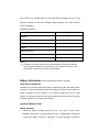
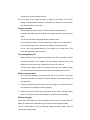
THANK YOU!
We are grateful for your purchase of the product. We believe this easy–to-use
radio will provide you with dependable and reliable communications. This
portable two-way radio is a precision device. Treat it with care, and you will
enjoy years of reliable operation.
MODELS COVERED IN THIS MANUAL
RP3600 VHF Professional Two-way Radio
RP3600 UHF Professional Two-way Radio
1
Contents
Safety and General Information
Product Safety and RF Exposure Compliance
FCC Licensing Information
Products Inspection
Battery Information
Antenna Information
Accessory Installation
Battery
Antenna
Belt Clip
Earplug Cover
External Earphone/Microphone (optional)
Getting Started
Features and Operation
Turn on/off the radio
Adjust the Volume
Power-on Password (only for keypad model)
Keypad Lock/Unlock (only for keypad model)
Select Channel
Transmit
Receive
Monitor
Repeater/Talk Around
Repeater/ Reverse Frequency
Power Level
Scan
Call
Emergency ANI/Emergency Alert
Record
VOX Feature
Low Battery Alert
MDC 1200 Function
English Menu Operation
Troubleshooting Guide
Care and Cleaning
Optional Accessories
2
Frequency Chart
Safety and General Information
The following general safety precautions as would normally apply, should be
observed during all phases of operation, service and repair of this equipment.
!
This equipment should be serviced by qualified technicians only.
!
Do not modify the radio for any reason.
!
Use only the original batteries and chargers.
!
Use only the supplied or an approved antenna.
!
Do not use any portable radio that has a damaged antenna. If a damaged
antenna comes into contact with your skin, a minor burn can result.
!
For vehicles with an air bag, do not place a radio in the area over an air bag or
in the air bag deployment area. Air bags inflate with great force. If a radio is
placed in the air bag deployment area and the air bag inflates, the radio may be
propelled with great force and cause serious injury to occupants of the vehicle.
!
Turn off your radio prior to entering any area with a potentially explosive
atmosphere.
!
Do not charge your battery in a potentially explosive atmosphere.
!
To avoid electromagnetic interference and/or compatibility conflicts, turn off your
radio in any facility where posted notices instruct you to do so. Hospital or
health facilities may be using equipment that is sensitive to external RF energy.
!
When instructed to do so, turn off your radio when on board an aircraft. Any use
of a radio must be in accordance with airline regulations or crew instructions.
!
To avoid possible interference with blasting operations, turn off your radio when
you are near electrical blasting caps, in a blasting area, or in areas posted:
“Turn off two-way radio.” Obey all signs and instructions.
!
Do not expose the radio to direct sunlight over a long time, nor place it close to
heating source.
3
!
When transmitting with a portable radio, hold the radio in a vertical position with
the microphone 5 centimeters away from your lips.
!
If you wear a radio on your body, ensure the radio and its antenna is at least 2.5
centimeters away from your body when transmitting.
WARNING: If you wear a radio on your body, ensure the radio and its
antenna is at least 2.5 centimeters away from your body when transmitting.
Product Safety and RF Exposure Compliance
Your two-way radio is designed and tested to comply with a number of national and
international standards and guidelines (listed below) regarding human exposure to
radio frequency electromagnetic energy. This radio complies with the IEEE (FCC)
and ICNIRP exposure limits for occupational/controlled RF exposure environment at
duty cycles of up to 50% talk-50% listen and should be used for occupational use
only. In terms of measuring RF energy for compliance with the FCC exposure
guidelines, your radio radiates measurable RF energy only while it is transmitting
(during talking), not when it is receiving (listening) or in standby mode.
Note: The approved batteries supplied with this radio are rated for a 5-5-90 duty
cycle (5% talk-5% listen-90% standby), even though this radio complies with the
FCC occupational RF exposure limits at duty cycles of up to 50% talk.
Your two-way radio complies with the following of RF en erg y exposure
standards and guidelines:
!
United States Federal Communications Commission, Code of Federal
Regulations; 47CFR part 2 sub-part J
!
American National Standards Institute (ANSI)/Institute of Electrical and
Electronic Engineers (IEEE) C95. 1-1992
!
Institute of Electrical and Electronic Engineers (IEEE) C95. 1-1999 Edition
!
International Commission on Non-Ionizing Radiation Protection (ICNIRP) 1998
4
!
Ministry of Health (Canada) Safety Code 6. Limits of Human Exposure to Radio
Frequency Electromagnetic Fields in the Frequency Range from 3KHz to 300GHz,
1999
!
Australian Communications Authority Radio communications (Electromagnetic
Radiation-Human Exposure) Standard 1999 (applicable to wireless phones
only)
Operational Instructions and Training Guidelines
To ensure optimal performance and compliance with the occupational/controlled
environment RF energy exposure limits in the above standards and guidelines, users
should transmit no more than 50% of the time and always adhere to the following
procedures:
Transmit and Receive
To transmit (talk), push the Push-To-Talk (PTT) button; to receive, release the PTT
button.
Hand-held radio operation
Hold the radio in a vertical position with the microphone one to two inches (2.5 to 5
cm) away from the lips.
Body-worn operation
!
Always place the radio in an approved clip, holder, holster, case, or body
harness for this product. Use of non-approved accessories may exceed FCC
RF exposure guidelines.
!
If you do not use an approved body-worn accessory and are not using the radio
in the intended use position in front of the face, then ensure the antenna and the
radio are kept one inch (2.5 cm) from the body when transmitting.
Antennas & Batteries
!
Use only the approved, supplied antenna or the approved replacement antenna.
Unauthorized antennas, modifications, or attachments could damage the radio
and may violate FCC regulations.
5
!
Use only the approved, supplied batteries or the approved replacement
batteries. Use of non-approved batteries may exceed FCC RF exposure
guidelines.
FCC Licensing Information
This equipment has been tested and found to comply with the limits for a Class B
digital device, pursuant to part 15 of the FCC Rules. These limits are designed to
provide reasonable protection against harmful interference in a residential
installation. This equipment generates, uses and can radiate radio frequency energy
and, if not installed and used in accordance with the instructions, may cause harmful
interference to radio communications. However, there is no guarantee that
interference will not occur in a particular installation. If this equipment does cause
harmful interference to radio or television reception, which can be determined by
turning the equipment off and on, the user is encouraged to try to correct the
interference by one or more of the following measures:
!
Reorient or relocate the receiving antenna.
!
Increase the separation between the equipment and receiver.
!
Connect the equipment into an outlet on a circuit different from that to which the
receiver is connected.
!
Consult the dealer or an experienced radio/TV technician for help.
FCC Requirements
Your radio must be properly licensed by the Federal Communications Commission
prior to use. Your wireless dealer can assist you in meeting these requirements. Your
dealer will program each radio with your authorized frequencies, signaling codes,
etc., and will be there to meet your communications needs as your system expands.
Products Inspection
Please carefully take the radio out of the box. We recommend that you confirm the
6
items listed in the following table are enclosed before discarding the box. If any
items are missing or have been damaged during shipment, file a claim with the
carrier immediately.
Available Accessories
Item
Qty. (pcs)
Antenna*
1
Belt Clip
1
Strap
1
Battery
1
Desktop Charger
1
AC Adapter
1
Owner’s Manual
1
*Notes:
① Frequency is marked on the color circle of the antenna. Red circle indicates
UHF and green indicates VHF. If frequency is not marked on the color circle,
please refer to the label on the main unit for details.
Battery Information (Take a keypad type model for example)
Initial use of the battery
The battery is not fully charged at the factory. Please charge the new battery before
initial use. In general, the battery should be charged for 12 hours before initial use,
which is suitable for Ni-Cd, Ni-MH or Li-ion battery charged with slow or rapid
charger. It is recommended to take this step during the first three times of use. When
the battery power is low, it needs to be charged.
Applicable Battery Packs
Safety attention
1. Conductive metals including jewelry, key, etc, may result in short circuit,
discharge, generation of a large quantity of heat, or leakage when coming into
contact with battery contacts or electrodes. To avoid damage to articles or
7
human injury, treat any battery with care.
2. Do not short out the battery terminals or dispose of the battery in fire. Never
attempt to disassemble the battery. If discarded, the battery should be thrown
into dedicated battery recycle box.
Normal operation
Please charge the battery indoor to ensure the optimal charging effect.
In general, the battery can be removed if the charger indicator turns from red to
green.
Turn off the radio when charging the battery inside the radio.
Do not charge the battery if its power hasn’t been used up (if the power used up,
the radio will give alert tone), otherwise, the battery life will be shortened.
Do not return fully charged batteries to the charger for an “extra boost”. This
action will significantly reduce cycle life.
To prolong battery life
Battery performance will be greatly decreased under -20℃ temperature. Please
use back-up battery in cold weather. The cold battery unable to work in this
situation may work under room temperature, so keep it for later use.
The dust on the battery contact may affect the life cycle of the battery. Please
use clean dry cloth to wipe it before the insertion of the battery into the radio.
Battery storage notice
1. Due to the self-discharge, the battery which will not be used for a long time
should be stored after full charge to avoid the damage to the battery because of
over-discharge.
2. Take out the battery stored for about 6 months to charge it, to avoid the influence
of electrolyte over-discharge on battery capacity.
3. Notice the ambient humidity and temperature for the battery storage. Please
store it in cool dry area with room temperature, to decrease self-discharge.
Battery charging
When radio LED flashes red and three Beeps sound every 30 seconds after the
battery is installed, that means battery power is low. Please charge the battery.
You are recommended to use the approved, supplied charger; Charger LED will
indicate the charging status.
8
LED
Indication
Flashing red
Low battery voltage
Red
Charging
Green
Fully charged
1. Plug the power cable into the adapter.
2. Plug the DC socket of adapter into the DC jack on the rear of the charger.
3. Insert the battery or the radio with battery into the charger cup.
4. Plug the AC socket of adapter into an AC outlet.
5. Make sure that the battery connectors are in contact with the charging terminals;
the charger LED glows red and charging begins.
6. The charger LED glows green when the battery is fully charged in about 3 hours,
please remove the battery or the radio with battery from the charger.
*Notes: Charger LED may flash red if you put the battery into the charger, which is a
normal pre-charge process for the charger to protect the battery when the battery
power is low. It will turn to normal charge status (glow red) after 30 seconds.
Antenna Information
1. Stubby antenna is ideal for communication within limited range. Thin and long
antenna optimizes communication coverage, its flexible and soft characteristic
makes it ideal for wearing your radio on the belt.
2. Communication range may vary with terrain and your operating conditions.
Rainy days or forest locations may narrow your communication range, please
make preparation in advance to avoid potential inconvenience.
9
Accessory Information (Take a keypad model for example)
Battery
Attaching the battery:
Insert the two tabs on bottom of the battery into the slots at the bottom of the radio.
Push the top of the battery towards the radio until a click is heard. (See figure 1)
Fig. 1
Removing the battery:
Turn off the radio. Push the battery latch on the middle of the radio to remove the
upper side of the battery away from the radio and then remove the battery. (See
figure 2)
Battery Latch
Fig. 2
Antenna
Insert the threaded end of the antenna into the connector on top of the radio. Rotate
the antenna clockwise to fasten it.
Rotate the antenna counterclockwise to remove it. (See figure 3)
10
Attach
Remove
Fig. 3
Belt Clip
Attaching Belt Clip:
Align the slot of the belt clip with the T-slot at the battery cover and press the belt
clip downwards until it is locked. (See figure 4)
Fig. 4
Removing the belt clip:
Press the disassembly release upwards with a key until it releases and then push
the belt clip upwards with your thumb to remove it. (See figure 5)
Disassembly Release
Fig.5
11
Earphone/Microphone Jack Cover
To remove the Earphone/Microphone jack cover, rotate the screw at the bottom of
the cover counterclockwise with a screwdriver until it is free. (See figure 6)
Fig. 6
External Earpiece/Microphone (Optional)
Insert the tab at the bottom of the earphone/microphone into the slot on the radio.
(See figure 7). Align the thumbscrew at top of the earphone/microphone with the
hole on the radio and turn it clockwise to fasten.
Fig. 7
12
Getting Started
(Keypad type model)
(1) Antenna
Used to transmit/receive signals.
(2) LED
The following table indicates LED mode and corresponding radio status:
LED
Status
Not lit
Standby
Green
Receive
Red
Transmit
Flashing green
Scan
Flashing red
Low battery voltage
Flashing orange
Call waiting
(3) Channel Selector
Used to select wanted channel.
(4) Programmable key [A]
13
(5) Power/Volume Control Knob
Rotate the Power/Volume Knob clockwise until a “click” is heard to turn the radio on;
rotate fully counter-clockwise to turn the radio off. When the radio is on, turn the
knob to adjust volume.
(6) Battery Latch
Used to fasten the battery.
(7) Speaker
Used to output receiver audio and alert tones
(8) Microphone
Used to input voice audio
(9) External Jack
Used to connect with external earphone or programming cable.
(10) Belt Clip
Used to clip the radio on your belt
(11) Battery Pack
(12) PTT key
Press and hold the PTT key to transmit. Release the PTT key to receive.
(13) Programmable Key [B]
(14) Programmable Key [C]
The following table shows the key function when:
•
Short pressed
•
Long pressed
Key Function
Short Press
Long Press
Emergency Alert
Enable emergency Alert
Disable emergency Alert
Monitor
Disable monitor
Monitor
Scan
Enter/Exit scan operation
Enter/Exit scan
operation
Nuisance Channel
Delete
Select High/Low
Power
Delete nuisance channel in
scan
Delete nuisance channel in scan
Select High/Low Power
Select High/Low Power
14
Repeater/Talk
Around
Repeater/Reverse
Frequency
Select Repeater or Talk
Around Mode
Select Repeater or Reverse
Frequency Mode
Select Repeater or Talk Around
Mode
Select Repeater or Reverse
Frequency Mode
Radio Call
Transmit a Call
Transmit a Call
Selective Call
Transmit selective call or
group call signalling (2-Tone)
or MDC shortcut key
Transmit selective call or group
call signalling (2-Tone) or MDC
shortcut key
Vibration
Toggle Vibration On/off
Toggle Vibration On/off
Priority Channel
Set
Set the current channel as
priority scan channel
Set the current channel as
priority scan channel
Record
Enter/Exit Record Function
Enter/Exit Record Function
Play back
Toggle Play Back feature
On/off
Toggle Play Back feature On/off
Delete Current Msg
Delete the Current Msg
Delete the Current Msg
Please contact your dealer for more details about the programmable keys.
(15) Function Keypad (See figure 8)
Exit: Used to return to the upper menu
Up key
Down key
Menu/Select Key: Used to enter menu mode. In menu mode, this key is used to
select options.
Exit
Up
Down
Menu
Fig. 8
(16) LCD Display
Used to indicate operation status of the radio and battery gauge.
(17) Numeric Keypad (See figure 9)
Used to input information under the program menu of the radio. (Only for a keypad
type model)
15
Fig. 9
16
Features and Operation
Turn On/Off the Radio
To turn the radio on, rotate the “Power/Volume” knob clockwise. An alert tone
indicates that the self-test of the radio completed successfully. The LED glows green
during power-up. If self-test fails and/or the selected channel is not set, you will also
hear an alert tone.
To turn the radio off, rotate the “Power/Volume” knob counterclockwise until a click is
heard.
Adjust the Volume
Rotate the “Power/Volume” knob to adjust the volume.
Power-on Password (Only for a keypad type model)
This radio offers password protection feature. “Password” will appear on LCD after
power on if password is set in the radio. The radio enters conventional mode after
entering 1-8 digit password.
Keypad Lock/Unlock (Only for a keypad type model)
Hold down
key and then press “*” key in 2 seconds to lock the keypad. When
the keypad is locked, holding down
key and then pressing “*” key in 2 seconds
can unlock the keypad. LCD displays “
” icon when keypad is locked.
Select Channel
The radio provides 256 conventional channels (16 zones, 16 channels in each zone).
Some of the channels may be not programmed and can’t be used. Please contact
your dealer for more details.
Rotate the “Channel Selector” knob to select the wanted channel.
1. Select an appropriate zone. (Refer to “select zone” in English Menu Mode).
2. Rotate “Channel Selector” knob until your wanted channel is selected.
Transmit
1. Turn on the radio.
17
2. Rotate the “Channel Selector” knob to select the wanted channel.
3. Make sure there is no activity on the channel.
4. Press the PTT key and speak into the microphone with your mouth 1- 2 inches
away from the radio. The LED glows red during transmission.
5. Release the PTT key to finish transmission.
Receive
1. Turn on the radio.
2. Rotate the “Channel Selector” knob to select the wanted channel.
3. Adjust the volume.
4. If vibration mode is set and a call is received, the radio will alert you with
vibration and no audio will be heard. The LED glows green during receiving.
5. When CTCSS/CDCSS or squelch tail elimination feature is set by your dealer:
•
No squelch tail will be heard at the end of a received transmission when the
courtesy tone is disabled.
•
A beep tone sounds at the end of a received transmission when the courtesy
tone is enabled.
Please contact your dealer for more details.
Monitor
1. Press Monitor key to monitor the current channel.
2. Press Monitor key again to exit.
3. Your dealer can set three monitor modes: SelCall monitor, CTCSS monitor and
Carrier monitor.
SelCall monitor: Radio shields selective call squelch condition when monitoring,
monitor status is activated if carrier and CTCSS are matched.
CTC/DCS monitor: Radio shields all signalling squelch condition when monitoring,
monitor status is activated if carriers are matched.
Carrier monitor: Radio shields all squelch condition and speaker is directly open.
4. If keep pressing monitor key more than 2 seconds, radio will be in stable monitor
18
status after the Monitor key is released.
Repeater/Talk Around
When you are out of the communication range of the repeater and within the
communication range of your group member, you can bypass the repeater and talk
directly to your group member.
Press the programmed Repeater/Talk Around key to select between “repeater” and
“talk around” mode. An alert tone indicates that radio is in talk around mode
(simplex). A different alert tone indicates that the radio is out of the talk around mode
(duplex).
Repeater/Reverse Frequency
When you are out of the communication range of the repeater and within the
communication range of your group member, you can talk with your group member
by reverse frequency when your group member is still within the communication
range of the repeater.
Press programmed Repeater/Reverse Frequency key to select between “repeater”
and “reverse frequency”. An alert tone indicates that radio operates in reverse
frequency mode. A different alert tone indicates that the radio is out of the reverse
frequency mode.
Note: “Repeater/Talk Around” and “Repeater/Reverse Frequency” cannot be set
simultaneously within one radio.
Power Level
Each channel of the radio can have different power levels that are user selectable.
•
High power allows you to transmit greater distances.
!
Low power helps to save battery life.
Press the programmed power select key to select high/low power. A positive alert
tone and a ‘Hi’ displayed on LCD indicate that radio is operating in high power level.
A relative alert tone and ‘Lo’ displayed on LCD indicate that radio is operating under
low power level.
19
Scan
Scan feature allows you to monitor activities on all channels for receiving call from
these channels.
When scan feature is enabled, the radio will detect calls from all channels. If an
active channel is detected, the radio will switch to that channel so that to receive an
incoming call(Channels must be programmed to be included in scan list).
Disable/Enable Scan Feature
1. Press the scan key to begin scanning.
2. Press the scan key again to stop scanning.
The LED flashes green in scan mode.
Callback
The radio will transmit on the callback channel if the PTT key is pressed while
scanning.
Please contact your dealer for more details about callback channel.
Nuisance Channel Delete
Nuisance channel delete feature allows you to temporarily delete an unwanted
channel from the scan list.
When the radio stops on the nuisance channel, press the programmed Nuisance
Delete key until an alert tone sounds to delete this channel.
When scan feature is enabled again, the deleted channel will return to the scan list.
Note: Priority channel cannot be deleted.
Priority Channel Scan
This feature allows you to scan important channels. The dealer can program a
channel as priority channel through the programming software.
Note: The radio will constantly monitor the priority channel when it stops on a
non-priority channel. If activity is detected on the priority channel, the radio will revert
to the priority channel and remain there as long as the channel stays active.
Please contact your dealer for more details.
20
Call
Press the programmed call key and the radio will send a preprogrammed signalling
code to compatible receivers with the same code. The compatible receiver is revived
and sounded an alert tone to draw the user’s attention.
Selective Call by Signalling
If Selective Call by Signalling is set in radio, specific radio will be selectively called
through this function. Selective Call only has 2-tone signalling.
Radio enters Call Waiting status after available selective call signalling is transmitted
or received. In Call Waiting status, indicator flashes orange. Exit Call Waiting if the
reset time of Call Waiting is over or monitor is pressed or selector knob is turned.
Please refer to the local dealer about the details of 2-tone selective call signalling.
Emergency ANI/Emergency Alert
The radio can be programmed to transmit an emergency ANI or emergency alert.
1. Press the Emergency Alert key to enable Emergency ANI or activate
Emergency Alert feature.
2. Press and hold the Emergency Alert key to disable Emergency ANI or
Emergency Alert feature.
VOX
Plug the earpiece into the earphone jack and activate VOX by menu operation.
1. Speak to the microphone and voice will be automatically transmitted.
2. Transmission is over when speak is stopped.
3. VOX is disabled when PTT key is repressed.
The VOX feature will be reactivated after switching the power off and then back on.
Record
Record and play can be performed when the radio is in receiving mode and no
signal appears.
Record
21
1. Press Record key or select Record feature in the menu to begin record.
2. When the memory is full and a new message is received, the oldest unprotected
message will be deleted. Unread message will not be deleted.
3. The radio stops recording when the record time elapses or any valid key is
pressed or when signal appears.
4. The radio can be set to delete all messages after power off (set by your dealer).
Play
1. Press Play key, the radio can play all the messages continuously starting from
newest to oldest. In the menu mode, you can select any message to play.
2. There is a one-second interval and an alert tone between two messages.
3. The radio stops playing when any valid key is pressed or signal appears. When
all the messages are played, the radio stops playing.
4. Press Delete key during playing to delete the selected message and continue to
play next one. You can select and delete a message through the menu mode.
The radio will sound an alert every two minutes to remind you of the new message.
Unread icon will be displayed. When all the new messages are played, the Unread
icon on LCD disappears.
Low Battery Alert
When the battery voltage becomes low, the red LED will flash and a beep sound is
heard. At this time, the battery should be replaced or recharged.
MDC 1200 Funtions
Transmit Selective Call
As long as radio agreement supports this function, user can transmit selective call to
another radio or group.
Transmit Selective Call:
1. Press
key or SelCall shortcut key (MDC1200 should be defined in
channel) to enter menu mode.
2. Press ◄ or ► key until MDC Function
3. Press
key to select
appears.
Selective Call
4. Press ◄ or ► key to select the needed call group in radio call list (Transmit ID
22
must be preset by programming software).
5. Press PTT key to transmit, then an alert tone will be sounded after transmission.
Radio will enter call waiting mode after it exits from menu mode.
6. Press PTT key to transmit, release it to receive.
7. Exit call waiting mode after reset.
Receive Selective Call
When user receives selective call, he will:
1. Hear the characterized alert tone that set by himself.
2. LED will flashes orange.
3. LCD will display Call Received and pre-programmed name or radio ID that is
calling to alternatively.
Transmit Call Alert Page
1. User can inform another people according to transmit call alert page.
Transmit call alert page:
1. Press
key or SelCall shortcut key to enter menu mode (MDC 1200 should
be defined in channel).
2. Press ◄ or ► key until
3. Press
key to select
MDC Function
Alert Call
appears.
.
4. Press ◄ or ► key to select the needed call group in radio call list (Transmit ID
must be preset by programming software).
5. Press PTT key to transmit, user will see
Transmitting
6. If Call Alert Page is received, user will see Page received, answer?
If Call Alert Page is not received, User will see
No response
7. Press PTT key to transmit, release it to receive.
8. Exit call waiting mode after reset.
Call Alert Page
When radio has received a call alert page, it will sound a characterized alert tone set
by user. Before user responses, the radio will display:
Go with Call Received, Call Received and pre-programmed name or radio ID that is
23
calling to be displayed alternatively. Press PTT key to response this information
page, terminate characterized alert tone, and press any key to clean up the
displayed content after exit from call waiting.
Radio Check
This function allows user to determine whether radio is in the range of disturbing
himself. Radio check is activated when failure happens after trying selective call and
call alert. This function only is used when radio signalling agreement support it.
Enforce a radio check:
1. Press
key or SelCall shortcut key to enter menu mode (MDC 1200 needs to
be defined in channel).
2. Press ◄ key or ► key until
3. Press
key to select
MDC Function
appears.
Radio Check
4. Press ◄ or ► key to select the needed call group in radio call list (Transmit ID
must be preset by programming software).
5. Press PTT key to transmit, user will see
Transmitting
6. If Call Alert Page is received, user will see Page received, answer?
If Call Alert Page is not received, User will see
24
No response
Alert Tone
High tone
Low tone
Operation
Description
Turn on the radio
Power on-Ready
Turn on the radio
Power on-Failure
Repeater/Talk Around
Repeater
Repeater/Talk Around
Talk Around
Repeater/Reverse
Repeater
Frequency
Repeater/Reverse
Reverse Frequency
Frequency
Select Power
High Power
Select Power
Low Power
Low Battery Alert Tone
Idle Channel Tone
PLL Unlock Tone
25
Audible Tone
Menu
Radio Check
Radio Alert
Unread MSG Alert
Selective Call
Play
Delete
Protect
Delete All MSG
Record
Message Option
Backlight
Power Level
VOX Level
Off 1, 2, 3
Menu Mode (Functions are subject to addition without prior notice)
MDC function
Voice Service
Channel Number
/Alias/Frequency
English
Level1-Level8
Zone 1-Zone 16
Squelch Level
26
Channel Display
Language
Talk Around/
Reverse Frequency
Tone Level
Utilities
Select Zone
Modify Name of Selective Call
Selective Call
Edit Call Alias
1-200 messages of
Selective Call List
Selective Call List
1. Press
key in squelch standby mode to enter the main menu and go to the
“ Selective call” item. Press [C] key to exit from the menu mode.
Selective Call
2. Press
key to enter selective call list and then press◄/►key to select
selective call name. Press
key to save the change and exit from the menu.
Press [C] key to return to the upper menu without saving the change.
Simon
Edit Selective Call Alias (By Keypad)
1. Press
in squelch standby mode to enter the main menu and then press
►key to enter “edit selective call alias” item.
Edit Selective
Call Alias
2. Press
key to enter selective call list and then press ◄/►key to select a call
alias; Repress
key to edit the selective call alias. Enter characters through
the numeric keyboard and press ◄/►key to move. Press
key to save the
change and return to the selective call list. Press [C] key to return to the
selective call list without saving the change. Press
above operation and [C] key to return to the main menu.
Call1
27
key to continue the
Note: Selective call alias can only be typed in English. To type in Chinese, user
should edit through programming software.
Select Zone
1. Press ►key to enter “select zone” item.
Select Zone
2. Press
key to enter the zone list (1-16) and press ◄/►key to select a zone.
Press
key to save the selected zone and return to the main menu. Press
[C] key to return to the main menu without saving the change.
Zone 6
Utilities
Squelch Level
1. Press ►key to enter “Utilities” menu.
Utilities
2. Press
key to enter the utilities menu. Press ◄/►key to select the item and
key to enter the item. After entering the item, LCD displays the current
squelch level (Off, level 1-3). Press ◄/►key to change the squelch level.
Squelch Level
3. Press
key to save the change and return to the utilities menu. Press [C]
key to return to the utilities menu without saving the change.
2
28
VOX Level
1. Enter the “Utilities” menu.
Utilities
2.
Press ►key to go to VOX item. Press
key to enter the item. LCD displays
current VOX level.
VOX Level
1
3. Press ◄/►key to change the VOX level (off, level 1-3). VOX feature is disabled
when “OFF” is displayed. Press
key to save the change and return to the
utilities menu. Press [C] key to quit without saving the change.
2
Power Level
1.
Enter the “Utilities” menu.
Utilities
2. Press ►key to go to “power level switch” item. Press
key to enter the item.
LCD displays power level option.
Power Level Switch
Power High
3. Press ◄/►key to toggle the power level (High/Low). Press
key to save the
change and return to the utilities menu. Press [C] key to quit without saving the
29
change.
Power Low
Backlight
1. Enter the “Utilities” menu.
Utilities
2. Press ►key to go to “backlight” item. Press
key to enter the item. LCD
displays backlight option.
Backlight
Off
3. Press ◄/►key to turn the backlight on/off. Press
key to save the change
and return to the utilities menu. Press [C] key to quit without saving the change.
On
Tone Level
1. Press ►key to go to “tone level” item.
Tone Level
2. Press
key to enter “tone level” (level 1-8) item. LCD displays current tone
level. Press ◄/►key to change the tone level. You will hear a confirmation tone
key to save the change and return to
about 1000HZ at the same time. Press
30
the utilities menu. Press [C] key to quit without saving the change.
6
Talk Around/Reverse Frequency
1. Press ►key to go to “talk around/reverse frequency” item.
Talk Around/Reverse
2. Press
key to enter this item. LCD displays the current transmit mode. Press
◄/►key to change the transmit mode. Press
key to save the change and
return to the utilities menu. Press [C] key to return without saving the change.
Reverse
Talk Around
Language
1. Press ►key to go to “language” item. Press
key to enter “language” item
and LCD displays the current language. Press ◄/►key to toggle the language
interface.
Language
3. Press
key to save the change and return to utilities list; Press [C] key to
return without saving change.
English
31
Note: Only English can be selected in current RP3600 model
Channel Display
1.
Press ►key to go to “channel display” item.
Channel Display
2.
Press
key to enter channel display item. LCD displays the current channel
display mode. Press ◄/►key to toggle the display mode. Press
key to
save the change and return to the utilities menu. Press [C] key to return without
saving the change. Channel display mode can be switched among channel
number, channel alias and receiving frequency.
Channel Number
Note:
1.
2.
Press ◄/►key in the main menu to toggle the setting item in the above order.
In the menu mode, the radio will return to the squelch standby mode
automatically without saving the setting if the display is kept for over 20 seconds
or the channel selector knob is rotated. The response to other keys is dealt with
the same way as the one of squelch standby mode.
3. Radio is endowed with Chinese/English interface. Sample listed above is taken
example in Chinese interface.
4. Support English input. Chinese input is temporarily not support.
Voice Service
Press ►key to go to “Voice Service” item. Press
Voice Service
32
key to enter the item.
Message Option
Press ◄/►key to enter “Message Option”. Press ◄/►key to select an item and
press
key to enter the selected item. After entering the item, press ◄/►key to
operate as following.
Message Option
Play :Play the selected message.
Delete: Delete the selected message.
Protect: Protect/Unprotect the selected message. “P” is displayed if a message is a
protected message.
Record
Press ◄/►key to enter “Record” item. Press
stops recording when the record time elapses or
key to begin recording. The radio
key is pressed again.
Record
Delete All Messages
Press ◄/►key to enter “delete all messages” item. Press
will be displayed. Press
key and “Delete All?”
key again to delete all messages. Press 【C】 key to
exit.
Delete All Msg
Unread Message Alert
Press ◄/►key to enter “Unread message alert” item. Press
33
key and “On”/”Off”
will be displayed. Press ◄/►key to toggle unread message alert on/off. Press
key to save the change. Press [C] key to exit.
Unread MSG Alert
! MDC Function
1.
Press ► key to go to “MDC function” item.
MDC Function
2.
Press
to enter and LCD displays the detailed function items. Press ◄/► to
toggle between the items and then press
SelCall
Press
to enter the selected item.
Alert Call
Radio Check
to enter the call list of selected functions. Press◄/► to go to
required call list. Press [C] key to go back to MDC function menu. Press the
PTT key to transmit the selected call list.
Call List Alias
or
MDC
Call
(1-200)
List
Remark: Alert message is the radio prompt message.
34
Appendix 1 LCD Display
Description
Signal Strength Indicator
Keypad Lock
Battery Power Indicator
Carrier Indicator
Speaker on
High/Low Power
Transmitting
Monitoring
Scanning
Call Waiting
Unread Message
Appendix 2 Entering Characters
Key
Number of times key is pressed
1
2
3
4
5
6
7
8
9
0
0
+
-
*
/
(
)
<
>
1
Space
1
,
.
’
”
:
!
?
2
A
B
C
2
a
b
c
r
s
y
z
3
D
E
F
3
d
e
f
4
G
H
I
4
g
h
I
5
J
K
L
5
j
k
l
6
M
N
O
6
m
n
o
7
P
Q
R
S
7
p
q
8
T
U
V
8
t
u
v
9
W
X
Y
Z
9
w
x
*
*
&
%
#
#
@
$
35
~
Trouble-shooting
Symptom
Solution
!
The battery is run out. Please
recharge the battery or replace it
Cannot power on the radio
with a fresh one.
!
The battery is not properly installed.
Please remove and reinstall the
battery.
The operation time will not increase
!
even though the battery is properly
The battery life cycle is over, please
replace with a new one.
charged.
!
Cannot talk to or hear group members.
Confirm
radios
channel,
and
have
the
same
CTCSS/CDCSS
settings.
!
Make sure you are within their
communication range.
!
Hear non-group members
Please change your CTCSS/CDCSS
settings, and so as your group
members.
Care and Cleaning
•
Avoid physical abuse to your radio such as carrying it by the antenna or by
the speaker microphone.
•
Wipe the battery contacts with a lint-free cloth to remove dirt, grease, or
other material that may prevent good electrical contact.
•
When not in use, keep the accessory jacks covered with the protective cap.
•
The case, controls, and keypad can be cleaned with a mild detergent and
36
warm water. Avoid using strong chemicals.
Optional Accessories
Antenna
Antenna
Remote speaker
SM08N1
Multi-unit Charger MCL01
Switch power for
charger PS2001
dual-slot
Three-wire surveillance earpiece
with transparent acoustic tube
EAN02
Earbud with in-line PTT ESN05
microphone
Dual-slot charger CH20L01
Receive- only earbud ESS01
Receive-only
earpiece
with
transparent acoustic tube ESS04
Light weight headset with in-line
PTT ECN07
Earpiece with in-line PTT &
transparent acoustic tube EAN03
37
Earbud with on-MIC PTT ESN06
Earpiece with on-MIC PTT&
transparent
acoustic
tube
EAN04
1-wire D-earset with boom MIC
& in-line PTT EHN08
D-earset with in-line MIC & PTT
EHN07
Light-weight,
behind-the-head
earpiece with in-line PTT ECN06
2-wire surveillance earpiece
with transparent acoustic tube
EAN05
3-wire surveillance earpiece with
transparent acoustic tube EAN06
2-wire surveillance earpiece with
transparent acoustic tube EAN07
2-wire neck
EWN03
Noise-cancelling
ECN09
High duty noise-cancelling
headset ECN08
Chest bag LCBN13
wireless earpiece
headset
Leather carrying case LCBY13
38
39
Frequency Chart
Model:
Serial Number:
CH
Rx Freq
Rx
CTC/DCS
Rx
Signal
Tx Freq
Tx
CTC/DCS
Signal
Type
Signal
Comb.
Band
Width
1
2
3
4
5
6
7
8
9
10
11
12
13
14
15
16
We endeavor to achieve the accuracy and completeness of this manual, but no warranty of
accuracy or reliability is given. All the above specifications and design are subject to change
without notice due to continuous development.
No part of this manual may be copied, reproduced, translated and stored in a retrieval system,
distributed, or transmitted in any form or by any means, electronic or mechanical, for any
purpose without the express written permission of us.
40