1
2.5 AMP MULTI-TOOL
Model No. 320.35078
• WARRANTY
• SAFETY
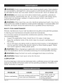
_WARNING:
To reduce the risk of injury,
read and understand the Operator's manual
before using this product.
Sears Brands Management
IL 60179 U.S.A.
www,
craftsman,com
Corporation,
Hoffrnan
• ASSEMBLY
• OPERATION
• MAINTENANCE
• ESPANOL
Estates,
Warranty
page 2
Safety Symbols
pages 4-5
Safety Instructions
pages 6-8
Description
pages 9-10
Assembly
pages 10-11
Operation
pages 12-25
Maintenance
page 26
Troubleshooting
page 26
Part List
pages 27-29
CRAFTSMAN
ONE YEAR LiMiTED
WARRANTY
FOR ONE YEAR from the date of purchase, this product is warranted
against any defects in material or workmanship.
With proof of purchase,
defective product will be replaced free of charge.
For warranty coverage
details
site: www.craftsman.com
to obtain
free replacement,
visit the web
This warranty does not cover the sandpaper, rasps or blades, which are
expendable parts that can wear out from normal use within the warranty
period.
This warranty is void if this product is ever used while providing
services or if rented to another person.
commercial
This warranty gives you specific legal rights, and you may also have other
rights which vary from state to state.
Sears Brands Management
Corporation,
Hoffman
Estates,
IL 60179
This multi-tool has many features for making its use more pleasant and
enjoyable. Safety, performance, and dependability
have been given top priority
in the design of this product making it easy to maintain and operate.
SAVE THESE INSTRUCTIONS!
READ ALL iNSTRUCTiONS!
Page 2
35078
ManuaLRevised_12
0615
,_, DANGER: People with electronic devices, such as pacemakers, should
consult their physician(s) before using this product. Operation of electrical
equipment in close proximity to a heart pacemaker could cause interference
failure of the pacemaker.
or
_,WARNING:
Some dust created by power sanding, sawing, grinding, drilling
and other construction activities contains chemicals known to the state of
California
examples
•
to cause cancer, birth defects
of these chemicals are:
Lead from lead-based
Crystalline
Arsenic
or other reproductive
paints,
silica from bricks and cement
and chromium
harm. Some
and other masonry
from chemically-treated
products,
and
lumber.
Your risk from these exposures varies, depending on how often you do this type
of work. To reduce your exposure to these chemical: work in a well ventilated
area, and work with approved safety equipment, such as those dust masks that
are specially designed to filter out microscopic
particles.
35078
Manual_Revised_12-0615
Page 3
The purpose
of safety symbols
is to attract your attention
to possible
dangers.
The safety symbols and the explanations with them deserve your careful
attention and understanding.
The symbol warnings do not, by themselves,
eliminate any danger. The instructions and warnings they give are no substitutes
for proper accident prevention measures.
WARNING:
Be sure to read and understand
all safety instructions
in this
manual, including all safety alert symbols such as "DANGER," "WARNING,"
and
"CAUTION"
before using this tool. Failure to follow all instructions listed in this
manual may result in electric shock, fire and/or serious personal injury.
SYMBOL
SIGNAL MEANING
SAFETY ALERT SYMBOL: Indicates DANGER, WARNING,
be used in conjunction with other symbols or pictographs.
,_
DANGER:
avoided,
,_
Indicates
an imminently
WARNING:
Indicates a potentially
which, if not
CAUTION:
Indicates a potentially
prevention
hazardous
situation,
which,
if not avoided,
injury.
could result in minor or moderate
Damage
situation,
may
will result in death or serious injury.
could result in death or serious
,_
hazardous
OR CAUTION;
hazardous
situation,
which, if not avoided,
injury.
and Information
Messages
These inform the user of important information and/or instructions that could
lead to equipment or other property damage if they are not followed. Each
message is preceded by the word "NOTICE", as in the example below:
NOTICE: Equipment
not followed.
,_, WARNING:
by a qualified
and/or
property
damage
may result if these instructions
To ensure safety and reliability,
all repairs should
are
be performed
service technician.
,_
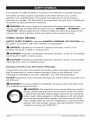
WARNING:
The operation
of any power tools can result in
foreign objects being thrown into your eyes, which can result
in severe eye damage. Before beginning power tool operation,
always wear safety goggles or safety glasses with side shield
and a full face shield when needed. We recommend a Wide
Vision Safety Mask for use over eyeglasses or standard safety
glasses with side shields. Always use eye protection which is
marked to comply with ANSI Z87.1.
Page 4
35078
ManuaLRevised_12
0615
SAVE THESE iNSTRUCTiONS
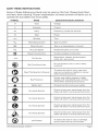
Some of these following symbols may be used on this tool. Please study them
and learn their meaning. Proper interpretation
of these symbols will allow you to
operate the tool better and more safely.
SYMBOL
NAME
V
D ESIGNATION/EXPLANATION
Volts
A
Voltage
Amperes
Current
Hz
Hertz
Frequency
W
Watt
Power
min
Minutes
'*_
Alternating
Direct
nO
]
.../min
Current
Current
Rotational
Per Minute
Read The Operator's
Safety
_,
No Hands
No Hands
No Hands
No Hands
Alert
Manual
Alert
Symbol
Symbol
Symbol
Symbol
Hot Surface
35078 Manual_Revised_12-0615
speed,
Double-insulated
of current
at no load
construction
Revolutions,
strokes, surface
orbits, etc., per minute
Eye Protection
O
Type of current
Type or a characteristic
II Construction
Wet Conditions
per second)
Time
No Load Speed
Class
(cycles
locations.
Do not expose
speed,
to rain or use in damp
read and understand
operator's
manual
To reduce the risk of injury, user must
before using this product.
glasses with side shields and a full face
Always wear safety goggles or safety
shield when operating
this product.
Precautions
that involve
your safety.
Failure will
blade
to result
keep your
in serious
hands personal
away frominjury.
the
Failure will
to result
keep your
hands personal
away frominjury.
the
blade
in serious
Failure will
blade
to result
keep your
in serious
hands personal
away frominjury.
the
blade
in serious
Failure will
to result
keep your
hands personal
away frominjury.
the
To reduce
avoid
contact
the with
risk of
anyinjury
hot surface.
or damage,
Page 5
GENERAL
POWER TOOL SAFETY WARNINGS
,_, WARNING:
Read and understand
instructions in this Operator's
serious personal injury.
Save all warnings
=
all instructions.
Failure to follow all
Manual may result in electric shock, fire, and/or
and instructions
for future
reference.
The term "power tool" in all warnings listed below refers to corded
tools or battery-operated
(cordless) power tools.
WORK
power
AREA SAFETY
•
Keep your work area clean and well lit. Cluttered or dark areas invite accidents.
•
Do not operate power tools in explosive environments,
such as in the
presence of flammabJe liquids, gases, or dust. Power tools create sparks,
which may ignite the dust or fumes.
•
Keep children and bystanders
away while operating
Distractions may cause you to lose control.
a power tool.
ELECTRICAL SAFETY
=
Power tool plugs must match the outlet. Never modify the plug in any
way. Do not use any adapter plugs with grounded power tools. Unmodified
plugs and matching outlets will reduce the risk of electric shock.
=
Avoid body contact with grounded
surfaces, such as pipes, radiators,
ranges, and refrigerators.
There is an increased risk of electric shock if
your body is grounded.
=
Do not expose power tools to rain or wet conditions.
power tool will increase the risk of electric shock.
•
Do not abuse the cord. Never use the cord for carrying, pulling, or
unplugging the power tool. Keep the cord away from heat, oil, sharp edges,
or moving parts. Damaged or entangled cords increase the risk of electric
shock.
Water entering a
When operating
a power tool outdoors,
use an extension
cord suitable
for outdoor use. Use of a cord suitable for outdoor use reduces the risk of
electric shock.
if operating
a power tool in a damp location is unavoidable,
use a
ground fault circuit interrupter (GFCl} protected supply. Use of a GFCI
reduces the risk of electric shock.
Page 6
35078
ManuaLRevised_12
06:$5
PERSONAL SAFETY
•
Stay alert, watch what you are doing and use common sense when
operating a power tool. Do not use the tool while tired or under the
influence of drugs, alcohol, or medication. A moment of inattention while
operating power tools may result in serious personal injury.
•
Use personal protective equipment.
Always wear eye protection.
Protective equipment, such as a dust mask, non-skid safety shoes, hard
hat, or hearing protection, used for appropriate conditions, will reduce
personal injuries.
•
Prevent unintentional
starting.
Ensure that the switch is in the OFF
position before connecting to a power source and/or battery, picking up
or carrying the tool. Carrying power tools with your finger on the switch or
energizing power tools that have the switch turned on invites accidents.
Remove any adjusting
key or wrench before turning the power tool
on. A wrench or a key left attached to a rotating part of the power tool may
result in personal injury.
•
Do not overreach.
Keep proper footing and balance at all times.
enables better control of the power tool in unexpected situations.
This
•
Dress properly. Do not wear loose clothing or jewelry. Keep your hair,
clothing and gloves away from moving parts. Loose clothes, jewelry or long
hair can be caught in moving parts.
•
If devices are provided for the connection
of dust extraction
and
collection
facilities,
ensure that these are connected
and properly used.
Use of these devices can reduce dust-related hazards.
POWER TOOL USE AND CARE
•
Do not force the power tool. Use the correct power tool for your
application. The correct power tool will do the job better and more safely at
the rate for which it was designed.
•
Do not use the power tool if the switch does not turn it on and off. Any
power tool that cannot be controlled with the switch is dangerous and must
be repaired.
•
Disconnect
the plug from the power source and/or the battery from the
power tool before making any adjustments,
changing accessories,
or
storing power tools. Such preventive safety measures reduce the risk of
starting the power tool accidentally.
•
Store idle power tools out of the reach of children and do not allow
persons unfamiliar
with the power tool or these instructions
to operate
the power tool. Power tools are dangerous in the hands of untrained users.
•
Maintain power tools. Check for misalignment or binding of moving parts,
breakage of parts and any other condition that may affect the power tool
operation. If damaged, have the power tool repaired before use. Many
accidents are caused by poorly maintained power tools.
35078
Manual_Revised_12-0615
Page 7
Keep cutting
sharp cutting
tools sharp and clean. Properly maintained cutting tools with
edges are less likely to bind and are easier to control.
Use the power tool, accessories,
tool bits, etc. in accordance
with
these instructions, taking into account the working conditions
and the
work to be performed.
Use of the power tool for operations different from
those intended could result in a hazardous situation.
SERVICE
Have your power tool
identical replacement
tool is maintained.
Follow
instructions
serviced by a qualified
repair person using only
parts. This will ensure that the safety of the power
in the Maintenance
section
unauthorized parts or failure to follow Maintenance
a risk of shock or injury.
SPECIFIC
SAFETY
of this manual.
instructions
Use of
may create
RULES FOR MULTI-TOOL
•
Hold power tools by their insulated gripping surfaces when performing
an operation where the cutting tool may contact hidden wiring or its
own cord. Contact with a" live" wire will make exposed metal parts of the
tool live and will shock the operator.
•
A suitable breathing
respirator
must be worn while sanding
some woods and metal to avoid breathing
the harmful/toxic
=
Always wear safety goggles
when sanding over-head.
and a dust mask
=
The machine
for wet sanding.
=
Do not use sanding paper larger than needed. Extra paper extending
beyond the sanding pad can cause serious lacerations.
=
Secure the workpiece.
A workpiece clamped
vice is held more securely than by hand.
=
Wear protective gloves when changing
become hot after prolonged use..
=
Keep hands away from the cutting range. Do not reach under the
workpiece. Contact with the blade can lead to injuries.
Page 8
is not suitable
lead paint,
dust or air.
when sanding,
with clamping
cutting
tools.
35078
especially
devices or in a
Cutting tools
ManuaLRevised_12
0615
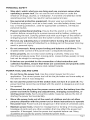
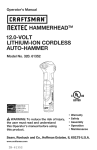
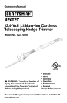
KNOW YOUR MULTI=TOOL
(Fig. 1}
Fig. 1
On/Off Switch
Quick-Release
Live Tool
Lever
Indicator
Light
Drive Shaft
Ribs
_[ange
Variable-Speed
PRODUCT
SEPCIFICATIONS
Input
2.5 Amps
Rating
120V, 60Hz, AC
Oscillation
Rate
11000-19000/min
Oscillation
Angle
_+1.4degrees
Tool Weight
_,
WARNING:
Bolt
Dial
3.5 Ibs.
The safe use of this product
requires
an understanding
of the
information on the tool and in this operator's manual as well as knowledge of the
project you are attempting. Before use of this product, familiarize yourself with
all operating features and safety rules.
35078
Manual_Revised_12-0615
Page 9
QUICK-RELEASE
LEVER
The quick-release
lever allows for tool-less
VARIABLE=SPEED
ADJUSTMENT
The variable-speed
dial is located
appropriate speed.
exchange
of application
tools.
DiAL
on the back of your tool for selecting
the
LED WORKLIGHT
The LED worklight
light for increased
is located
visibility.
LIVE TOOL INDICATOR
in the front of the tool. This feature
WARNING:
extra
LIGHT
The light shines green when tool is plugged
,_
provides
into a power source.
If any parts are broken or missing, do not attempt
to plug the
multi-tool to a power source or operate the multi-tool until the broken or missing
parts are replaced. Failure to do so could result in serious injury.
_1_ WARNING:
Do not attempt
to modify this tool or create accessories
not
recommended
for use with this multi-tool. Any such alteration or modification
misuse and could result in a hazardous condition leading to serious injury.
,_
WARNING:
To prevent accidental
starting
that could cause serious
injury, always unplug the tool from the power source when assembling
is
personal
parts.
UNPACKING
•
Carefully remove the tool and any accessories from the carton.
that all items listed in the packing list are included.
Make sure
Inspect the tool carefully
during shipping.
occurred
to make sure no breakage
Do not discard the packing material
satisfactorily operated the tool.
If any parts are damaged
of purchase.
PACKING
or missing,
or damage
until you have carefully
inspected
please return the product
to the place
LiST
Multi-tool, flush cut blade, scraper blade, carbide triangular rasp, carbide
circular blade, circular saw blade, sanding plate and sandpapers, carrying
and operator's manual.
Page 10
and
35078
Manual_Revised_12
bag
0615
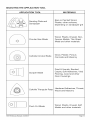
SELECTING
THE APPLiCATiON
APPLiCATiON
TOOL
TOOL
MATERIALS
Sanding Plate and
Sandpaper
Bare or Painted Wood,
Plaster, other surfaces,
depending on sandpaper
Circular Saw Blade
Wood, Plastic, Drywall, NonFerrous Metals, Thin Sheet
Metal and other materials
Carbide Circular
Grout, Plaster, Porous
Concrete and Masonry
Blade
Paint & Varnish, Bonded
Carpet, Soft Adhesives, Vinyl
Flooring, wood and other
Floor Coverings.
Scraper Blade
Carbide Triangular
Flush Cut Blade
35078
Manual_Revised_12-0615
grit
Rasp
Hardened Adhesives,
Wood and Masonry
Thinset,
Wood, Plastic, Drywall, Soft
Metals and other materials
Page 11
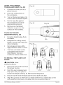
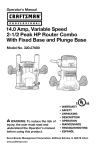
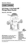
ON/OFF
SWITCH
(Fig. 2)
1.
Connect the power cord of
your multi-tool to a standard
household power outlet.
2.
To turn the tool ON, push the
on/off switch forward.
3.
To turn the tool OFF, pull the
on/off switch backward.
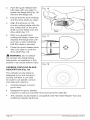
VARIABLE=SPEED
DIAL (Fig. 3)
The variable-speed
feature on this
multi-tool allows you to match the
proper speed to the material being
cut, sawed, scraped or sanded,
enhancing the overall performance
of your tool and helping to save the
application tool from undue wear.
1.
The variable-speed
dial is
used to adjust the speed of
the application tool.
2.
Turn the dial to increase or
decrease the speed of the
tool (Fig. 3).
3.
Position
Fig. 2
"1" selects
Fig. 3
Variable-speed
dial
the
slowest speed; position "6"
selects the fastest speed.
Adjust the application
tool speed for optimum
performance.
Fig. 4
LED worklight
NOTICE: Determine the optimum
speed by making a trial cut in a
scrap piece of material.
LED WORKLIGHT
(Fig. 4)
The LED worklight, located on
the front of the tool, will illuminate when the on/off switch is in the forward
(ON) position, and will turn off when the switch is pulled backwards (OFF). The
worklight provides additional light for operation in lower-light conditions.
Page 12
35078
ManuaLRevised_12
0615
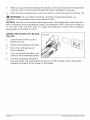
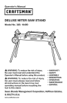
LiVE TOOL iNDiCATOR
(Fig. 5}
LIGHT
:ig. 5
Live tool indicator
light
The live tool indicator light is a
green light located on the back
of the tool. This light is always on
when the multi-tool is plugged into
a power source.
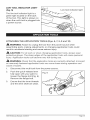
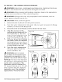
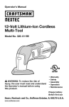
ATTACHING
THE APPLiCATiON
,_k WARNING:
TOOLS (Figs. 6, 7, 8, 9 and 10}
Failure to unplug the tool from the power source when
assembling parts, making adjustments, or changing application
result in accidental starting and cause serious injury.
,_, CAUTION:
For all work or when changing
application
tools could
tools, always wear
protective gloves. The sharp edges of the application tools will cause personal
injury. Application tools can become very hot during use.
WARNING:
Check that the application
or insecurely fastened
cause a hazard.
application
1.
Disconnect
2.
Push the quick-release
lever
fully open with your palm to
loosen the flange bolt (Fig. 6).
Remove the flange bolt.
3.
35078
the multi-tool
tools are correctly
attached,
tools can come Boose during operation
incorrect
and
from the power source.
Fig. 6
Ensure that the inner threads
and the drive shaft are clean.
Manual_Revised_12-0615
Page 13
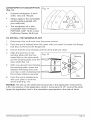
4.
Align the grooves on the
application tool with the four
raised ribs on the drive shaft.
Fig. 7
Put the application tool onto
the drive shaft (Figs. 7 and 8).
5.
With your gloved hand
holding the application tool,
insert and depress the flange
bolt until you hear a click
indicating that the application
tool is secured (Fig. 9).
6.
Push the quick-release
lever
with your palm to lock the
driver shaft (Fig. 10).
Fig. 8
NOTICE: Attach the application
tool in the desired orientation
for the task at hand. The shaft is
configured so that the application
tool can be attached at 0 °, 45 °,
90 °, 270 ° and 315 °. The flush
cut blade, the scraper blade, the
carbide circular blade and the
circular saw blade should never
be attached so that they are
facing backwards.
,_
WARNING:
Fig. 9
Do not attach the
flush cut blade, the scraper blade,
carbide circular blade or circular
saw blade facing backwards, as
operation in this position may
cause serious injury.
Page 14
35078
ManuaLRevised_12
0615
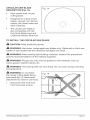
SANDPAPER KIT DESCRmPTION
(Fig. 11)
•
9 pieces sandpaper: 3 each
of 60, 120, and 180 grit.
•
Always apply to the compatible
sanding plate (supplied with
your multi-tool).
Fig. 11
The sandpaper kit is also
compatible with the Bosch
PMF180E, GOP 10.8V Li and
Craftsman Nextec Multi-tool.
TO mNSTALL THE SANDING
PLATE
1.
Disconnect
2.
Push the quick-release
Bever fully open with your palm to Boosen the flange
bolt (Fig. 6). Remove the flange bolt.
3.
4.
the multi-tool
from the power source.
Ensure that the inner threads
and the drive shaft are clean.
Align the grooves on the
sanding plate with the four
raised ribs on the drive shaft;
Fig. 12
Groove
put the sanding plate onto the
drive shaft (Fig. 12).
5.
6.
With your gloved hand holding
the sanding plate, insert and
depress the flange bolt until
you hear a click indicating that
the scraper blade is secured.
Push the quick-release
Bever
Rib
with your palm to lock the
driver shaft (Fig. 10)o
NOTICE: The ribs on the shaft and the grooves in the application tools permit
a firm connection of the application tools in increments of 45 ° around the shaft.
Apply the application tool in the orientation appropriate to the task at hand.
35078
Manual_Revised_12-0615
Page 15
TO iNSTALL
(Fig. 12a)
,_
THE SANDPAPER
WARNING:
Check that the
Fig. 12a
Sandpaper
sanding plate and sandpaper are
correctly attached. An incorrect or
insecurely fastened application tool
can come loose during operation
and cause a hazard.
1.
Follow the directions
for
attaching the application tool
to attach the sanding plate to
the multi-tool.
2.
Align the sandpaper with the sanding
firmly onto the sanding plate.
3.
Press the sandpaper firmly against a smooth surface for a short period of
time, then turn on the tool. The burr will form a non-slip bond with the outer
edge of the sandpaper felt. This will avoid premature wear.
4.
If one point has become worn, pull off the sandpaper,
it on the sanding plate again.
SANDING
,_
(Fig. 13}
WARNING:
plate and use your hand to press it
turn it 120 ° and place
13
Do not touch the
motor housing after prolonged
use; it could be very hot.
=
The removal
rate and
the sanding pattern are
determined
by the choice
of sanding sheet and the
work surface.
Apply uniform sanding
pressure to extend the life of
the sanding sheets.
•
Intensifying the sanding pressure does not lead to an increase of the
sanding capacity; it increases wear on the machine and the sanding sheet.
For precise sanding of edges, corners
tip or an edge of the sanding sheet.
and hard to reach areas, use only the
When selectively sanding on one spot, the sanding sheet can heat up
considerably.
Remove the tool from the surface periodically to permit the
sanding sheet to cool down.
A sanding sheet that has been used for metal should
other materials.
•
Use only Craftsman
Page 16
not be used for
sanding accessories.
35078
Manual_Revised_12
0615
CIRCULAR
SAW BLADE
DESCRiPTiON
{Fig° 14}
High=speed steel circular
cutting blade.
Designed for cutting wood,
plastic, drywall, non=ferrous
metals, thin sheet metal and
other materials.
The circular saw blade is
also compatible with the
Fein Multi=Master tool and
Craftsman Nextec Multi=tool.
TO mNSTALL THE CIRCULAR
CAUTION:
Wear protective
WARNING:
SAW BLADE
gloves.
Use sharp, undamaged
blades or saw blades that are otherwise
WARNING:
When sawing
and the recommendations
_
saw blades only. Deformed
damaged
light building
materials,
observe
the precautions
d the material suppliers.
WAF{NmNG: Plunge cuts may only be applied
wood, gypsum
or blunt saw
can break.
to soft materials,
such as
plaster boards, etc.
WARNING:
The sawing teeth are very sharp. Do not touch during mounting
and application.
WARNING:
Do not attach
the circular cutting blade facing
backwards (fig 15). Backwards
attachment my result in user injury.
1.
Disconnect
Fig. 15
the multi=tool
from the power source.
35078
Manual
Revised
12-0615
Page 17
2.
Push the quick-release lever
fully open with your palm to
loosen the flange bolt (Fig. 16).
Remove the flange bolt.
3.
Ensure that the inner threads
and the drive shaft are clean.
4.
Align the grooves on the
circular cutting blade with the
four raised ribs on the drive
Fig. 16
shaft; put the blade onto the
drive shaft (Fig. 17).
5.
With your gloved hand
holding the blade, insert and
depress the flange bolt until
you hear a click indicating
that the blade is secured.
6.
Press the quick-release
lever
with your palm to lock the
drive shaft (Fig. 10).
,_
WARNING:
Fig. 17
©
Do not attach
the circular saw blade facing
backwards, as operation in this
position may cause serious injury.
Fig. 18
CARBIDE
CIRCULAR
DESCRiPTiON
BLADE
(Fig. 18)
The carbide circular
blade is
designed to cut out the grout
around wall tiles. It can also
be used to cut plaster, porous
concrete and masonry.
•
Carbide-tipped,
grout disc.
circular
Designed for grout, plaster,
masonry or porous concrete
removal around
The carbide circular blade is compatible
Craftsman Nextec Multi-tool.
Page 18
the wall tiles.
with Fein Multi-Master
35078
Tool and
ManuaLRevised_12
06:$5
TO iNSTALL THE CARBIDE CIRCULAR BLADE
WARNING:
Use sharp, undamaged
blades or saw blades that are otherwise
_,
WARNING:
When sawing
and the recommendations
_,
WARNING:
damaged
light building
blunt saw
can break.
materials,
observe
the precautions
of the material suppliers.
Plunge cuts may only be applied
wood, gypsum
plaster boards,
_,
Wear protective
CAUTION:
saw blades only. Deformed,
the multi-tool
to soft materials,
such as
etc.
gloves.
1.
Disconnect
from the power source.
2.
Push the quick-release
lever fully open with your palm to loosen the flange
bolt (Fig. 6). Remove the flange bolt.
3.
Ensure that the inner threads
4.
Align the grooves on the
carbide circular blade with the
four raised ribs on the drive
and the drive shaft are clean.
Fig. 19
shaft; put the application tool
onto the drive shaft (Fig. 19).
5.
With your gloved hand holding
the blade, insert and depress
the flange bolt until you hear a
click indicating that the carbide
circular blade is secured.
6.
Push the quick-release
lever
with your palm to lock the
driver shaft (Fig. 10).
Fig. 20
WARNING:
Do not attach
the carbide circular blade facing
backwards, as operation in this
position may cause serious injury.
NOTICE: The ribs on the shaft and
the grooves in the application tools
permit a firm connection of the
application tools in increments of
45 ° around the shaft, at 0% 45 ° , 90 ° ,
270 ° and 315 ° (Fig. 20). Apply the
application tool in the orientation
appropriate to the task at hand.
OO
270 °
35078
Manual_Revised_12-0615
45 °
90 °
315 °
Page 19
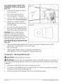
CUTTING
CARBIDE
GROUT WiTH THE
CIRCULAR
BLADE
_.Fig. 21
(Fig. 21)
1.
Connect
the multi-tool
to a
power source.
2.
Draw the cutting lines on
the workpiece, if desired.
3.
Turn on the tool and allow it to
come to the full desired speed.
4.
Place the carbide circular
blade against the workpiece
at a 90 ° angle.
5.
Fig. 22
Cut out the grout around the
tile, then use a hand chisel to
remove the tile from the wall.
NOTICE: When cutting grout,
masonry and porous cement,
take into consideration
that the
application tools wear heavily when
used for longer periods of time.
SCRAPER
(Fig. 22)
•
BLADE DESCRiPTiON
Steel scraping blade designed for paint & varnish,
adhesives, vinyl flooring, wood and other
floor coverings.
The scraper
Multi-Master
TO iNSTALL
,_
WARNING:
insecurely
a hazard.
soft
blade is also compatible with the Fein
Tool and Craftsman Nextec Multi-tool.
THE SCRAPER
A
,_L CAUTION:
bonded carpet,
Wear protective
BLADE
gloves.
Check that the application
fastened
application
attached.
Incorrect
or
and cause
1.
Disconnect
2.
Push the quick-release
lever fully open with your palm to loosen the flange
bolt (Fig. 6). Remove the flange bolt.
3.
Ensure that the inner threads
Page 20
the multi-tool
tool is correctly
tool can come loose during operation
from the power source.
and the drive shaft are clean.
35078
ManuaLRevised_12
06:$5
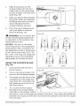
4.
Align the grooves on the
scraper blade with the four
raised ribs on the drive shaft;
put the scraper onto the drive
shaft (Fig. 23).
5.
With your gloved hand holding
the blade, insert and depress
the flange bolt until you hear a
click indicating that the
scraper blade is secured.
6.
Push the quick-release
lever
with your palm to lock the
driver shaft (Fig. 10).
_,
WARNING:
23
Groove
Rib
Fig. 24
Do not attach the
scraper blade facing backwards,
as operation in this position may
cause serious injury.
NOTICE: The ribs on the shaft
and the grooves in the application
tools permit a firm connection of
the application tools in increments
of 45 ° around the shaft, at 0°, 45 °,
90 °, 270 °, 315 ° (Fig. 24). Apply the
application tool in the orientation
appropriate to the task at hand.
USING THE SCRAPER
(Fig. 25}
1.
Connect
90 °
BLADE
the multi-tool
270 °
315 °
to a
power source.
2.
45 °
0o
Fig. 25
Turn on the tool and allow it to
come to the full desired speed.
3.
To scrape, put the tool on the
workpiece at a flat angle (not
more than 20°), and apply only
light pressure so as to not cut
into the surface.
4.
To cut and remove carpet,
first place the scraper blade
vertically on the carpet, switch
the tool on, and cut through the carpet to the floor. Then place the blade flat
between the carpet and the floor to remove the adhesive and free the carpet
from the floor.
35078
Manual_Revised_12-0615
Page 25
CARBIDE TRIANGULAR
DESCRIPTION
(Fig. 26)
Carbide tipped
grout rasp.
RASP
Fig. 26
triangular
Designed for grout, masonry,
thinset, wood and removal of
hardened adhesives on the
wall tiles.
The triangular rasp is also
compatible with the Fein MultiMaster Tool and Craftsman
Nextec Multi-tool.
Fig. 27
Groove
TO INSTALL THE CARBIDE
TRIANGULAR
RASP
,_
CAUTION:
protective
1.
Wear
gloves.
Disconnect the multi-tool
from
the power source.
2.
3.
4.
Push the quick-release
lever
fully open with your palm to
loosen the flange bolt (Fig. 6).
Remove the flange bolt.
Ensure that the inner threads
and the drive shaft are clean.
i
Fig. 28
Align the grooves on the
carbide triangular rasp with the
four raised ribs on the drive
shaft; put the rasp onto the
drive shaft (Fig. 28).
5.
With your gloved hand holding
the triangular rasp, insert and
depress the flange bolt until
you hear a click indicating that
the scraper blade is secured.
6.
Push the quick-release
lever with your palm to lock the driver shaft (Fig. 10).
NOTICE: The ribs on the shaft and the grooves in the application tools permit
a firm connection of the application tools in increments of 45 ° around the shaft
(from 0° to 315°). Apply the application tool in the orientation appropriate to the
task at hand.
Page 22
35078
ManuaLRevised_12
06:$5
USING THE CARBIDE
TRIANGLUAR
RASP (Fig. 29}
1.
Connect
the multi-tool
Fig. 29
to a
power source.
2.
Draw the cutting
the workpiece.
lines on
3.
Turn on the tool and allow it to
come to the full desired speed.
4.
5.
Put the rasp flat against
the workpiece and apply
appropriate pressure.
Fig. 30
Groove
Remove any hardened
adhesive or grout on the
surface of the wall tiles.
FLUSH CUT BLADE
DESCRiPTiON (Fig. 30}
•
Bi-metal, straight-edge,
cut blade.
flush-
Designed for cutting wood,
plastic, drywall, soft metal and
other materials.
Fig. 31
Can plunge and saw with a
slight pendulum action in wood.
The flush cut blade is also
compatible with the rein
Multi-Master Tool and
Craftsman Nextec Multi-tool.
TO iNSTALL
BLADE
,_
CAUTION:
protective
1.
THE FLUSH CUT
0°
45 °
90 °
Wear
gloves.
Disconnect
the multi-tool
from
the power source.
2.
3.
4.
35078
Push the quick-release
lever
270 °
fully open with your palm to
loosen the flange bolt (Fig. 6). Remove the flange bolt.
Ensure that the inner threads
315 °
and the drive shaft are clean.
Align the grooves on the flush-cut blade with the four raised ribs on the
drive shaft; put the flush-cut blade onto the drive shaft (Fig.31).
Manual_Revised_12-0615
Page 23
5.
With your gloved hand holding the blade, insert and depress the flange bolt
until you hear a click indicating that the flush-cut blade is secured.
6.
Push the quick-release
WARNING:
operation
lever with your palm to lock the driver shaft (Fig. 10).
Do not attach the flush cut blade, facing backwards,
in this position
may cause serious
as
injury.
NOTICE: The ribs on the shaft and the grooves in the application tools permit a
firm connection of the application tools in increments of 45 ° around the shaft, at
0% 45 °, 90 °, 270 ° and 315 ° (Fig. 31). Apply the application tool in the orientation
appropriate to the task at hand.
USING THE FLUSH CUT BLADE
(Fig. 32)
1.
Connect
the multi-tool
Fig. 32
to a
power source.
2.
Clamp the workpiece securely.
3.
Draw the cutting
the workpiece.
4.
Turn on the tool and allow it to
lines on
come to the full desired speed.
5.
Cut the workpiece along the
line and apply with appropriate
pressure until the blade cuts to the depth
needed according to the scale on the blade.
Page 24
35078
ManuaLRevised_12
0615
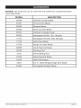
NOTICE: The multi-tool
can be used with the Craftsman
accessories
below
(sold separately):
MODEL
67650
Carbide Circular
67651
Circular Saw Blade
67652
Scraper Blade
67653
Flush Cut Saw Blade
67654
Carbide Triangular
67655
Sandpaper
Kit (60, 120, 180 grit)
17374
Sandpaper
Kit (220, 280, 320 grit)
17375
Detail Saw Blade
17376
Rough Cut Saw Blade
30858
Caulk Removal
30753
Sanding
3102
Blade
Pad
Felt Polishing
Pad
Detail Sanding
31023
Detail Sandpaper
25494
Manual_Revised_12-0615
Rasp
blade
31022
2549
35078
DESCRIPTION
Blade
3/4-in. Detail Straight
Enlongated
Straight
Edge Saw Blade
Blade
Page 25
_!_,WARNING:
Avoid using solvents
when cleaning
plastic
parts. Most plastics
are susceptible to damage from various types of commercial solvents and may
be damaged by their use. Use clean cloths to remove dirt, dust, oil, grease, etc.
_,.WARNING:
Do not at any time allow brake fluids,
gasoline,
based products,
penetrating
oils, etc. to come in contact
Chemicals can damage, weaken or destroy plastic which
serious personal injury.
WARNING:
When servicing,
use only identical
petroleum-
with plastic parts.
may result in
replacement
parts. Use of any
other parts may create a hazard or cause product damage. To ensure safety and
reliability, all repairs should be performed by a qualified service technician.
MULTI=TOOL
MAINTENANCE
Periodic maintenance
A cleaning
of your multi-tool allows for long life and trouble-free
and maintenance
schedule
As a common-sense
and preventive
recommended
steps:
•
Inspect the application
Keep the ventilation
the motor.
should
operation.
be maintained.
maintenance
practice,
follow these
tools; check the rim for wear or damage.
slots of the motor clean to prevent
overheating
of
Use a soft clean and damp cloth to wipe the tool housing. A mild detergent
can be used but nothing like alcohol, petrol or other cleaning agent. Never
use caustic agents to clean plastic parts.
_IL WARNING:
When changing
allow the application
_,
WARNING:
_1_ WARNING:
an application
tool immediately
tool to cool before removing
after operation,
it to avoid possible
Keep the tool's air vents unclogged
burning.
and clean at all times.
Water must never come into the tool.
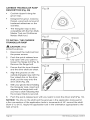
LUBRICATION
All of the bearings in this tool are lubricated with a sufficient amount of high-grade
lubricant for the life of the tool under normal operating conditions. Therefore, no
further lubrication is required.
PROBLEM
CAUSE
Motor overheating
Be sure cooling vents are free
from dust and obstacles,
Page 26
SOLUTION
Clean, clear vents. Do
not cover with hand
during operation.
35078
ManuaLRevised_12
0615
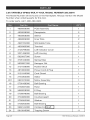
2.5A VARIABLE=SPEED
MULTI-TOOL
MODEL
NUMBER
The Model Number will be found on the Nameplate.
Number when ordering parts for this tool.
320.35078
Always mention
the Model
To order parts, call 1-800-469-4663.
÷
35078
Manual_Revised_12-0615
Page 27
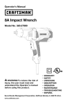
2.5A VARIABLE=SPEED
MULTI-TOOL
MODEL
NUMBER
The Model Number will be found on the Nameplate.
Number when ordering parts for this tool.
320.35078
Always mention
the Model
To order parts, call 1-800-469-4663.
4890939000
PCB Assembly
1
2
4930038000
Receptacle
2
3
4930008000
Sleeve
2
4
4860006000
Inner Wire
2
5
4920154000
Shrinkable
6
4930385000
Terminal
7
3126799000
Left Indicator
8
3321486000
Left Housing
1
9
5620037000
Screw
1
10
3705120000
Spring Stop
1
11
5630001000
Hexagon
1
12
3121038000
Rubber Stick
1
13
4810002000
Power Cord & Plug
1
14
3121045000
Cord Guard
1
15
2740305000
Stator
1
201
2823372000
Motor Assembly
1
16
5700199000
Ball Bearing
1
17
2750937000
Rotor
1
18
5660028000
E Ring
1
19
5700048000
Ball Bearing
1
2O
3704682000
Counterweight
1
21
3700352000
Washer
1
22
5700205000
Ball Bearing
1
23
5660144000
Circlips ForF_-
24
5610040000
Tapping
Page 28
Tube
2
2
Cover
1
Nut
_
1
Screw
11
35078
ManuaLRevised_12
0615
25
3321487000
Right Housing
1
26
5610024000
Tapping
2
27
3120234000
Cord Anchorage
28
3126800000
Right Indicator
29
3126796000
Switch Actuator
1
30
3551798000
Bush
2
31
3402598000
Lever
1
32
5670317000
Pin
1
33
2800176000
Brush Holder
2
34
4960273000
Carbon Brush
2
35
4930036000
Receptacle
2
36
3126797000
LED Cover
1
37
5700040000
Oil Impreging
38
2823250000
Quick Clamp Assembly
1
39
3551760000
Lock Pole
1
40
3520628000
Lever
1
41
3550031000
Washer
2
301
3810537000
Wood & Metal Plunge Cut Blade
1
302
3810540000
Scraper Blade
1
303
3810562000
Carbide Grout Removal Blade
1
304
3810563000
Flush Cut Blade (HSS)
1
305
3321331000
Base Plate Set
1
306
2820442000
Sanding Paper
9
307
3810542000
Rasper
1
35078
Manual_Revised_12-0615
Screw
1
Cover
Bearing
1
1
Page 29
Page
30
35078
ManuaLRevised_12
06i5
35078
Manual_Revised_12-0615
Page
31